Table of Contents
Troubleshooting

Related Manuals for JRC JMA-932B-SA


Summary of Contents for JRC JMA-932B-SA
- Page 1 JMA-933B-SA JMA-933B-SA JMA-932B-SA JMA-932B-SA JMA-923B-7XA/9XA JMA-923B-7XA/9XA JMA-922B-6XA/9XA JMA-922B-6XA/9XA MARINE RADAR MARINE RADAR EQUIPMENT EQUIPMENT RADAR MODE RADAR MODE INSTRUCTION MANUAL INSTRUCTION MANUAL...
- Page 3 Cautions for High Voltage High voltages, ranging from several hundreds to tens of thousands of volts, are used in electronic apparatus, such as radio and radar instruments. These voltages are totally harmless in most operations. However, touching a component inside the unit is very dangerous. (Any person other than authorized service engineers should not service, inspect, or adjust the unit.) High voltages on the order of tens of thousand volts are most likely to cause instant deaths from electrical shocks.
- Page 4 Method of First-Aid Treatment ☆Precautions for First-Aid Treatments Whenever a person is struck by an electrical shock, give the patient artificial respiration immediately on the spot, unless it is absolutely necessary to move the patient for safety's sake. Once started, artificial respiration should be continued rhythmically.
- Page 5 ☆Treatment to Give When the Patient Has a Pulse Beating but Has Ceased to Breathe *Performing mouth-to-mouth artificial respiration - Fig. 1 Bend the patient's face backward until it is directed to look back. (A pillow may be placed under the neck.) Pull up the lower jaw to open up the airway.
- Page 6 ☆Treatment to Give When the Patient Has No Pulse Beating and Has Ceased to Breathe *Performing cardiac massage - Fig. 2 If the patient has no pulse beating, with the pupils open and no heartbeat being heard, the patient has a cardiac arrest and requires immediate artificial respiration.
-
Page 7: Preface
●PREFACE● Thank you very much for purchasing the JRC marine radar equipment, JMA-900B series. This equipment is a marine radar equipment designed to obtain safe operation of marine ships. This equipment consists of a radar signal transmitter-receiver unit, a LCD display unit and a scanner unit as its main units. -
Page 8: Before Operation
●Before Operation● Pictorial Indication Various pictorial indications are included in this manual and are shown on these equipment so that you can operate them safety and correctly and prevent any danger to you and/or to other persons and any damage to your property during operation. -
Page 9: Precautions
●PRECAUTIONS● DANGER Never conduct inspection or repair work of equipment componts. Inspection or repair work by uncertified personnel may result in fire hazard or electric shock. For inspection and repair work of equipment components, consult with our branch office, branch shop, salea office, or our distributor in your district. - Page 10 WARNING Never directly touch the internal components of the scanner or indicator. Diect contact with these high-voltage components may cause electric shock. For maintenace, inspection, or adjustment of equipment components, consult with our branch office, branch shop, sales office, or our distributor in your district. To contact our sales department, branch offices, branch shops, and sales offecs: Prese refer to the “Office List”...
- Page 11 WARNING When conducting maintenance work, make sure to turn off the power so that the power supply to the equipment is completely cut off. Some equipment components can carry electrical current even after the power switch is turned off, and conducting maintenance work may result in electric shock, equipment failure, or accidents.
- Page 12 WARNING Do not insert and remove the USB device while transmitting. The radar image becomes unstable by accessing the USB device not acticipated, and it causes the breakdown.
- Page 13 CAUTION Use the radar only as a navigation aid. The final navigation decision must always be made by the operator him/herself. Making the final navigation decision based only on the radar display may cause accidents such as collisions or running aground. Use Target Tracking (TT) function only as a navigation aid.
- Page 14 CAUTION When setting a guard zone, make sure to properly adjust gain, sea-surface reflection suppression level, and rain/snow reflection suppression level so that the optimal target images are always on the radar screen. The guard zone alarm will not be activated for targets undetected by the radar, and it may result in accidents such as collisions.
- Page 15 CAUTION Do not directly touch the inverter circuit of the LCD display with a bare hand since high voltage temporarily remains in the circuit even after the main power is shut off. Failure may result in electric shock. Any adjustments must be made by specialized service personnel. Incorrect settings may result in unstable operation.
- Page 16 The Mounting Point of the Warning Label Warning Label NCD-2096 Display Unit Warning Label Front face Back face NWZ-170-E/ET Monitor Unit...
- Page 17 Warning Label NDC-1444 Process Unit (Desktop Type) Warning Label NQE-3141-4A/8A Interswitch Unit - XI...
- Page 18 Warning Label NQE-3167 Power Control Unit Warning Label NKE-1129-7/9 Scanner Unit NKE-1125-6/9 Scanner Unit...
- Page 19 Warning Label NKE-1139/1130 Scanner Unit Warning Label NTG-3230/3225 Transmitter Receiver Unit - XIII...
-
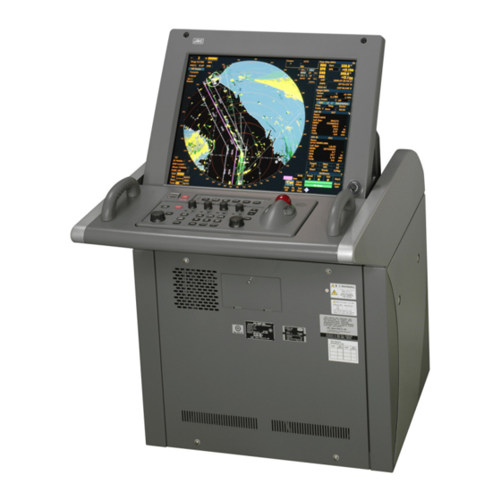
Page 20: Equipment Appearance
●EQUIPMENT APPEARANCE● Scanner Unit Type NKE-1130 (12 feet) Scanner Unit Type NKE-1139 (12 feet) Transmitter Receiver Unit Type NTG-3230(30kW) - Page 21 Scanner Unit Type NKE-1129-7 (7 feet) Scanner Unit Type NKE-1129-9 (9 feet) Transmitter Receiver Unit Type NTG-3225(25kW) - XV...
- Page 22 Scanner Unit Type NKE-1125-6 (6 feet) Scanner Unit Type NKE-1125-9 (9 feet) Power Control Unit Type NQE-3167 (Option)
- Page 23 Display Unit Type NCD-2096 (Stand alone type) Inter Switch Unit Type NQE-3141-4A (Option) - XVII...
- Page 24 Monitor Unit Type NWZ-170-ET (Desktop type) Operation Unit Type NCE-5163-FT (Desktop type) Radar Processing Unit Type NDC-1444 (Desktop type) DISPLAY UNIT TYPE NCD-2096F (DESKTOP TYPE) XVIII...
-
Page 25: Glossary
●GLOSSARY● This section describes the main terms used for this equipment and general related maritime terms. Acquisition/Activation zone A zone set up by the operator in which the system should automatically acquire radar targets and activate reported AIS targets when entering the zone. - Page 26 Course Over Ground The direction of the ship's movement relative to the earth, measured on board the ship, expressed in angular units from true north CORREL CORRELation CPA/TCPA The distance to the Closest Point of Approach and Time to the Closest Point of Approach.
- Page 27 H up Head up Own ship’s heading line is always pointed to the top center of the radar display. International Hydrographic Office International Maritime Organization Interswitch Unit A device to switch over two or more radar display units and two or more scanners.
- Page 28 POSN POSitioN Pulse Repetition Frequency The number of radar pulses transmitted each second. PROC PROCess Radar signal processing function Radar beacon A navigation aid which responds to the radar transmission by generating a radar signal to identify its position and identity Radar cross-section Radar cross-section of a target determines the power density returned to the radar for a particular power density incident on the target...
- Page 29 Sea state Status of the sea condition due to the weather environment, expressed as a sea state 0 for flat conditions with minimal wind, to sea state 8 for very rough sea conditions. The current direction for manual correction or the current speed on the horizontal axis of the 2-axis log is displayed.
- Page 30 Time To Go. Time to next waypoint. TXRX Transceiver Unit Universal Time Coordinated. The international standard of time, kept by atomic clocks around the world. Voyage Data Recorder Variable Range Marker An adjustable range ring used to measure the distance to a target. Waypoint A geographical location on a route indicating a event.
-
Page 31: Table Of Contents
CONTENTS PREFACE ......................I BEFORE OPERATION ..................II PRECAUTIONS ....................III EQUIPMENT APPEARANCE ................ XIV GLOSSARY ....................XIX Contents SECTION 1 GENERAL AND EQUIPMENT COMPOSITION FUNCTIONS..................1-1 1.1.1 Function of This System ..................1-1 FEATURES ..................1-2 CONFIGURATION................1-4 EXTERIOR DRAWINGS............... 1-6 GENERAL SYSTEM DIAGRAMS ............ - Page 32 3.2.2 Change Observation Range [RANGE+/-] ............3-6 3.2.3 Tune........................3-7 3.2.4 Adjust Gain [GAIN].....................3-8 3.2.5 Suppress Sea Clutter [SEA] ................3-9 3.2.6 Suppress Rain/Snow Clutter [RAIN] ..............3-11 3.2.7 Reset Alarm Buzzer [ALARM ACK]..............3-12 3.2.8 Adjust to the Best Image..................3-13 OPERATION PROCEDURES ............3-14 3.3.1 Move Cross Cursor Mark by Trackball.............3-14 3.3.2 Operate Software Buttons ................3-14 3.3.3 Operation of Combobox...................3-15...
- Page 33 3.5.2 Save Own Ship’s Track Data ................3-39 3.5.3 Cancel Saving of Own Ship’s Track Data (Own Track Memory) ......3-39 3.5.4 Clear Own Ship’s Track Data (Clear Own Track)..........3-39 3.5.5 Use Expanded Own Ship's Track (Own Track Type) ........3-40 3.5.6 Use Water Depth Track (Water Depth Setting) ..........3-41 3.5.7 Use Water Temperature Track (Water TEMP Setting) ........3-42 3.5.8 Use Current Track (Current Setting) ..............3-43 3.5.9 Loading and Saving of Own Track (File Operation) .........3-44...
- Page 34 3.9.2 Function Setting Menu Items ................3-92 3.9.3 Overview of Function Operations (User Function Setting).......3-93 3.9.4 Overview of saved Function Setting Data............3-96 3.10 USE USER SETTING................. 3-97 3.10.1 Save Operating State (Save User Setting) ............3-97 3.10.2 Load Operating State (Load User Setting).............3-98 3.10.3 Delete Operating State (Delete User Setting) ..........3-98 3.11 USING FILE MANAGER ..............
- Page 35 5.1.1 Collision Avoidance....................5-3 5.1.2 Definitions of Symbols ..................5-6 5.1.3 Radar Display ....................5-11 5.1.4 Cursor Modes (Cursor) ..................5-13 5.1.5 Setting Collision Decision Criteria..............5-15 5.1.6 Setting CPA Ring .....................5-15 5.1.7 Setting Vectors (Vector Time) ................5-16 5.1.8 Setting the GPS antenna location..............5-16 TARGET TRACKING OPERATION ...........
- Page 36 SEA CLUTTER AND RAIN AND SNOW CLUTTER ......6-5 FALSE ECHOES .................. 6-9 DISPLAY OF RADAR TRANSPONDER (SART) ....... 6-12 DISPLAY OF AIS-SART..............6-14 SECTION 7 SETTINGS FOR SYSTEM OPERATION SETTINGS AT INSTALLATION............7-1 7.1.1 How to Open the Serviceman Menu ..............7-1 7.1.2 GYRO I/F Setting....................7-2 7.1.3 Tuning (Tune Adjustment)..................7-4 7.1.4 Tune Indicator Adjustment .................7-4...
- Page 37 SECTION 8 MAINTENANCE ROUTINE MAINTENANCE ..............8-1 REGULAR BACKUP................8-2 MAINTENANCE ON EACH UNIT ............8-5 8.3.1 Scanner Unit NKE-1125/1129/1130/1139............8-5 8.3.2 Wave Guide Tube (JMA-923B-7XA/9XA) ............8-8 8.3.3 Coaxial Cable (JMA-933B-SA) ................8-8 8.3.4 Transmitter-Receiver Unit NTG-3225/3230 ............8-8 8.3.5 Display Unit NCD-2096..................8-9 PERFORMANCE CHECK..............
- Page 38 10.5 ABOUT THE CHINA RoHS..............10-3 SECTION 11 SPECIFICATIONS 11.1 JMA-933B-SA TYPE RADAR ............... 11-1 11.2 JMA-932B-SA TYPE RADAR ............... 11-2 11.3 JMA-923B-7XA/9XA TYPE RADAR ............. 11-3 11.4 JMA-922B-6XA/9XA TYPE RADAR ............. 11-4 11.5 SCANNER UNIT (NKE-1139)..............11-5 11.6 SCANNER UNIT (NKE-1130)..............11-5 11.7 SCANNER UNIT (NKE-1129-7/9) ............
- Page 39 APPENDIX B Interconnection diagram / System diagram / Connection diagram Gyro settings ....... B-1 INDEX...
- Page 41 GENERAL AND EQUIPMENT COMPOSITION NAMES AND FUNCTIONS OF CONTROL PANEL KEYS AND FUNCTIONS OF SOFTWARE BUTTONS BASIC OPERATION MEASUREMENT OF RANGE AND BEARING OPERATION OF TARGET TRACKING AND AIS TRUE AND FALSE ECHOES ON DISPLAY SETTINGS FOR SYSTEM OPERATION MAINTENANCE TROUBLESHOOTING AND AFTER-SALES SERVICE DISPOSAL...
- Page 43 1SECTION 1 GENERAL AND EQUIPMENT COMPOSITION 1.1 FUNCTIONS....................1-1 1.2 FEATURES ....................1-2 1.3 CONFIGURATION ..................1-4 1.4 EXTERIOR DRAWINGS ................1-6 1.5 GENERAL SYSTEM DIAGRAMS............. 1-22...
-
Page 44: Functions
* Refer to this manual for the RADAR mode functions and operations. There is a separate ECDIS mode manual for CHART functions. During Chart-Radar operation the ECDIS functions are slightly amended compared to the comparable JRC ECDIS only model JAN-901B/JAN-701B. -
Page 45: Features
1.2 Features FEATURES Realization of Large, Easy-to-see Screen with High Resolution The 23.1-inch color LCD with high resolution of 1600 × 1200 pixels can display radar images of 320 mm or more in diameter. Even short-range targets can also be displayed as high-resolution images. Target Detection by Latest Signal Processing Technology The system employs the latest digital signal processing technology to eliminate undesired clutter from the radar video signals that are obtained from the receiver with a wide dynamic range, thus improving... -
Page 46: Performance Monitor
Compact Design and Low Power Consumption Since an LCD has been implemented as the display device, the weight of the display is greatly reduced and the power consumption is lowered in comparison with the conventional radar equipment. Self-diagnostic Program Incorporated The Self-diagnostic program always monitors all the functions of the system. -
Page 47: Configuration
Rate of Radar model Antenna type Output Band Category rotation Power JMA-933B-SA 12ft Slotted Antenna 30kW 24rpm CAT 1C JMA-932B-SA 12ft Slotted Antenna 30kW 24rpm CAT 1C JMA-923B-7XA 7ft Slotted Antenna 25kW 24rpm CAT 1C JMA-923B-9XA 9ft Slotted Antenna 25kW... - Page 48 H-7AWRD0003 JMA-923B-7XA/9XA FR-9 H-7AWRD0004 6. In JMA-933B, the following type name of JRC is used for the RF coaxial cable between the scanner unit and the transmitter receiver unit. Type of Radar RF COAX cable Length (m) Type name of JRC...
-
Page 49: Exterior Drawings
1.4 Exterior Drawings EXTERIOR DRAWINGS Fig. 1.1 Outline Drawing of Scanner Unit, Type NKE-1139 Fig. 1.2 Outline Drawing of Scanner Unit, Type NKE-1130 Fig. 1.3 Outline Drawing of Scanner Unit, Type NKE-1129-7 Fig. 1.4 Outline Drawing of Scanner Unit, Type NKE-1129-9 Fig. - Page 50 Fig. 1.1 Outline Drawing of Scanner Unit, Type NKE-1139...
- Page 51 1.4 Exterior Drawings Fig. 1.2 Outline Drawing of Scanner Unit, Type NKE-1130...
- Page 52 Fig. 1.3 Outline Drawing of Scanner Unit, Type NKE-1129-7...
- Page 53 1.4 Exterior Drawings Fig. 1.4 Outline Drawing of Scanner Unit, Type NKE-1129-9 1-10...
- Page 54 Fig. 1.5 Outline Drawing of Scanner Unit, Type NKE-1125-6 1-11...
- Page 55 1.4 Exterior Drawings Fig. 1.6 Outline Drawing of Scanner Unit, Type NKE-1125-9 1-12...
- Page 56 Fig. 1.7 Outline Drawing of Transmitter Receiver Unit, Type NTG-3230 1-13...
- Page 57 1.4 Exterior Drawings Fig. 1.8 Outline Drawing of Transmitter Receiver Unit, Type NTG-3225 1-14...
- Page 58 Fig. 1.9 Outline Drawing of Display Unit, Type NCD-2096 1-15...
- Page 59 1.4 Exterior Drawings Fig. 1.10 Outline Drawing of Monitor Unit, Type NWZ-170-ET (Desktop type option) 1-16...
- Page 60 Fig. 1.11 Outline Drawing of Radar Processing Unit, Type NDC-1444 (Desktop type option) 1-17...
- Page 61 1.4 Exterior Drawings Fig. 1.12 Outline Drawing of Operation Unit, Type NCE-5163-FT (Desktop type option) 1-18...
- Page 62 Fig. 1.13 Outline Drawing of Inter switch Unit, Type NQE-3141-4A (Option) 1-19...
- Page 63 1.4 Exterior Drawings Fig. 1.14 Outline Drawing of Inter switch Unit, Type NQE-3141-8A (Option) 1-20...
- Page 64 Fig. 1.15 Outline Drawing of Power Control Unit, Type NQE-3167 (Option) 1-21...
-
Page 65: General System Diagrams
1.5 General System Diagrams GENERAL SYSTEM DIAGRAMS Fig. 1.16 General System Diagram of Radar, Type JMA-933B-SA Fig. 1.17 General System Diagram of Radar, Type JMA-932B-SA Fig. 1.18 General System Diagram of Radar, Type JMA-923B-7XA Fig. 1.19 General System Diagram of Radar, Type JMA-923B-9XA Fig. - Page 66 Note: Eliminating the interference on frequencies used for marine communications and navigation due to operation of the radar. All cables of the radar are to be run away from the cables of radio equipment. (Ex. Radiotelephone. Communications receiver and direction finder, etc. ) Especially inter-wiring cables between scanner unit and display unit of the radar should not be run parallel with the cables of radio equipment.
- Page 67 (Ex. Radiotelephone. Communications receiver and direction finder, etc. ) Especially inter-wiring cables between scanner unit and display unit of the radar should not be run parallel with the cables of radio equipment. Fig. 1.17 General System Diagram of Radar, Type JMA-932B-SA 1-24...
- Page 68 NKE-1129-7 SCANNER UNIT NJU-85 PERFORMANCE HEATER OPTION MONITOR CIRCUIT BREAKER (SHIP YARD SUPPLY) (5A) AC100V,50/60Hz 1φ,100W ( W I T H M O N ) 0 . 6 / 1 k V - D P Y C Y S - 1 . 5 F L E X I B L E W A V E G U I D E NBL-175 F R - 9 ( J R C S U P P L Y )
- Page 69 1.5 General System Diagrams NKE-1129-9 SCANNER UNIT NJU-85 PERFORMANCE HEATER OPTION MONITOR CIRCUIT BREAKER (SHIP YARD SUPPLY) (5A) AC100V,50/60Hz 1φ,100W ( W I T H M O N ) 0 . 6 / 1 k V - D P Y C Y S - 1 . 5 F L E X I B L E W A V E G U I D E NBL-175 F R - 9 ( J R C S U P P L Y )
- Page 70 Note: Eliminating the interference on frequencies used for marine communications and navigation due to operation of the radar. All cables of the radar are to be run away from the cables of radio equipment. (Ex. Radiotelephone. Communications receiver and direction finder, etc. ) Especially inter-wiring cables between scanner unit and display unit of the radar should not be run parallel with the cables of radio equipment.
- Page 71 1.5 General System Diagrams NKE-1125-9 SCANNER UNIT NJU-85 PERFORMANCE HEATER OPTION MONITOR CIRCUIT BREAKER (SHIP YARD SUPPLY) (5A) AC100V,50/60Hz 1φ,100W ( W I T H M O N ) 0 . 6 / 1 k V - D P Y C Y S - 1 . 5 NBL-175 SHIP’S MAIN for HEATER...
- Page 72 1-29...
-
Page 73: Section 2 Names And Functions Of Control Panel Keys
2SECTION 2 NAMES AND FUNCTIONS OF CONTROL PANEL KEYS AND FUNCTIONS OF SOFTWARE BUTTONS 2.1 NAMES OF DISPLAY .................2-1 2.2 NAMES AND FUNCTIONS OF CONTROL PANEL KEYS.......2-11 2.3 FUNCTIONS OF SOFTWARE BUTTONS..........2-16... -
Page 74: Names Of Display
NAMES OF DISPLAY Example of screen display In this example, the screen is divided into a number of areas and the names in each area are indicated. Upper left Upper right of the display of the display Own ship's information Target tracking (TT)/ AIS information... - Page 75 2.1 Names of Display Association target Own ship’s symbol アソシエーション目標 自船シンボル Ship’s heading 船首マーカー marker AIS target vector AIS目標ベクトル Ship’s heading line 船首輝線 AIS目標シンボル Cursor mark AIS target symbol カーソルマーク 自動捕捉・活性化領域 Automatic acquisition / activation zone AIS目標番号 AIS target number パストポジション...
- Page 76 Upper left of the display About ground and sea stabilization Speed sensor source is MAN , LOG , 2AXW When Set/Drift Setting menu is on : GND (Ground stabilization) When Set/Drift Setting menu is off : Sea (Sea stabilization) Speed sensor source is 2AXG , GPS : GND (Ground stabilization) Lower left of the display Double zoom On/Off...
- Page 77 2.1 Names of Display Upper right of the display Lower right of the display...
- Page 78 Own ship's information Operation status Heading device Ship's heading bearing Own ship's speed Speed sensor Own ship's course over ground Time display mode Own ship's speed over ground Positioning system Date and time (example: GPS, DGPS) Geodetic positioning system Own ship's latitude Own ship's longitude Target tracking (TT) / AIS information Target vector true/relative...
- Page 79 2.1 Names of Display Digital information: AIS target information AIS unread message Icon AIS target number Simple display item MMSI Ship’s name Call sign Course TCPA Speed Ship’s heading bearing Bearing Rate of turn Range Latitude Longitude Latitude/Longitude error Navigation status Destination...
- Page 80 Digital information: Tracked target information Digital information: Enhancement of cursor position numeric value indication...
- Page 81 2.1 Names of Display Digital information: Enhancement of EBL/VRM numeric value indication Digital information: Navigation information ① Water depth ② Water temperature ③ Current speed・ direction ⑦ Current layer switching ④ Wind speed・ direction ⑤ Current speed reference ⑥ True/Relative bearing switching Graphics indication: Water depth...
- Page 82 Graphics indication: Wind direction・wind speed・current ④ True/Relative bearing ② Wind direction switching ③ Wind speed unit switching ① Current direction Graphics indication: Water temperature...
- Page 83 2.1 Names of Display Menu Brilliance / Alarm Display information Scale display System SYNC Setting 2-10...
-
Page 84: Names And Functions Of Control Panel Keys
NAMES AND FUNCTIONS OF CONTROL PANEL KEYS The name of each button is described from the following page. 2-11... - Page 85 2.2 Names and Functions of Control Panel Keys [POWER] (Power supply) switch The lamp is lit and the equipment is activated. When switch is pressed while the equipment is running, the power of the equipment is shut down. → To section “3.1.1 Power ON and Start the System” [PWR ACK] (Power alarm acknowledgement) key Use this function to acknowledge the alarm when power supply abnormality occurs.
- Page 86 [RANGE +/-] (Range switching) key This function switches the range. Press [+] to increase the observation range. Press [-] to reduce the observation range. → To section “3.2.2 Change Observation Range” [EBL1] (Electronic Bearing Line 1) key Use this function to display and select EBL1. When the key is pressed for 2 seconds or more, the Marker Setting menu is displayed.
- Page 87 2.2 Names and Functions of Control Panel Keys [ACQ CANCEL] (Tracked target cancellation) key This function set a cursor mode to the acquisition cancel mode. When the key is pressed for 2 seconds or more, all the targets that are being tracked are cancelled. →...
- Page 88 [Track ball left button] Use this function to confirm menu selection and numeric value input. [Track ball right button] Use this function to reset menu selection and numeric value input. [TURN] (Turn) key This key is not used in the RADAR mode. [ROUTE PLAN] (Route Plan) key This key is not used in the RADAR mode.
-
Page 89: Functions Of Software Buttons
2.3 Functions of Software Buttons FUNCTIONS OF SOFTWARE BUTTONS In this radar, the frequently used functions can be directly set from the screen without opening the menu by using the software buttons on the screen for quick handling. The screen is divided into a number of areas and each area is named. - Page 90 Upper left of the display ①:Range scale switching To increase the observation range scale (maximum 96NM), click + and to reduce the range (minimum 0.125NM), click - . ②:Range rings display On / Off The display of range rings are set to On / Off whenever this button is clicked. When the display is set to On, the interval of the fixed range marker is displayed.
- Page 91 2.3 Functions of Software Buttons ⑥:Interswitch connection change This button is displayed when the interswitch is connected. This button indicates the connection status of the scanner unit that is connected to the indicator. When the button is clicked in the transmission standby state, the menu for changing the connection state between the scanner unit and the indicator is displayed.
- Page 92 ②:Interference rejection (IR) mode switching The list opens whenever this button is clicked. Clicking the item in the list, selects the interference rejection mode. Selecting item is IR Off , IR Low , IR Medium and IR High . ③:Target enhance (ENH) mode switching The list opens whenever this button is clicked.
- Page 93 2.3 Functions of Software Buttons Upper right of the display ①:Cursor bearing numeric value display true / relative switching The bearing numeric value display T (true bearing) / R (relative bearing) of the cursor is switched whenever this button is clicked. ②, ③, ④,and ⑤:EBL1 / 2 and VRM1 / 2 adjustment These functions set the EBL1 , VRM1 , EBL2 , and VRM2 acquire the operation right.
- Page 94 ⑫ and ⑬:EBL1 / EBL2 starting point mode switching The EBL starting point is set to CCRP or any position on the radar screen whenever this button is clicked. ⇒ C ⇒ D ⇒ : Center :The starting point is fixed to the CCRP position. : Screen Fix :The starting point is set to the cursor position.
- Page 95 2.3 Functions of Software Buttons Lower right of the display ①:Own ship's track color switching The own ship's track color is switched whenever this button is clicked. ②:Own ship's track interval switching The own ship's track interval is switched whenever this button is clicked. ③:Chart display On / Off The chart display is set to On / Off whenever this button is clicked.
- Page 96 Own ship's information ①:Speed sensor switching The speed sensor is switched whenever the button is clicked. MAN (Manual) ⇒ LOG (Single-axis water log) ⇒ 2AXW (Dual-axis water log) ⇒ 2AXG (Dual-axis ground log) ⇒ GPS ⇒ MAN When the selected speed device is not connected to the equipment, an alarm is issued. ※...
- Page 97 2.3 Functions of Software Buttons Target tracking (TT) / AIS information ①:Target vector display true / relative switching The tracked target / AIS target vector display is switched to T (true vector) / R (relative vector) whenever this button is clicked. This setting is switched together with the past position display true / relative switching.
- Page 98 ⑦:AIS function On / Off The AIS function is switched to On / Off whenever the button is clicked. ⑧:Tracked target symbol display On / Off The tracked target symbol display is switched to On / Off whenever the button is clicked. Use this function to avoid confusion with the AIS symbol.
- Page 99 2.3 Functions of Software Buttons Numerical display:AIS target information ② AIS unread message Icon Simple display item ① Detail / Simple display Switching ①:Detail / Simple display switching Switching display that detail or simple while AIS target information is displayed. ②:AIS unread message display When there are unread messages from displaying the AIS target, the unread message icon will be displayed.
- Page 100 Numerical display:Target Tracking (TT) information ①:TT information display scrolling When two or more pursuit target information is displayed, these information is permuted Note: The TT information display scrolling is applied from the display unit software: Ver. 2.00 2-27...
- Page 101 2.3 Functions of Software Buttons Digital information: Enhancement of EBL/VRM numeric value indication Digital information: Navigation information ① Water depth ② Water temperature ⑦ Current layer ③ Current speed・ switching direction ④ Wind speed・ direction ⑤ Current speed reference ⑥ True/Relative bearing switching Graphics indication: Water depth 2-28...
- Page 102 Graphics indication: Wind direction・wind speed・current ④ True/Relative bearing ① Wind direction switching ③ Wind speed unit switching ②Current direction Graphics indication: Water temperature 2-29...
-
Page 103: Chart Menu
2.3 Functions of Software Buttons Menu ①:Digital information display When the button is clicked while the menu screen is open, the menu is closed and control returns to the digital information display. This function switches between the tracked target / AIS target display and navigation information or the water depth graphics, and so on. - Page 104 Brilliance Display item switch Day/night mode Panel lighting switch brilliance switch Radar video Tracked target/AIS target brilliance switch symbol brilliance switch Display information Scale display System SYNC Setting( ※ 1 To display “System SYNC Setting”, the Display Unit is needed to the ※...
- Page 105 2.3 Functions of Software Buttons ①:Display item switch The brilliance adjustment screen, display information screen, scale display screen and System SYNC Setting(※1) interchange whenever button is clicked. ②:Panel lighting brilliance switch This function enables the setting of the brilliance of the lighting of the control panel. The brilliance changes whenever this button is clicked.
- Page 106 Alarm ①:Alarm acknowledgment When the button is clicked, the buzzer sound of the alarm that is currently issued is stopped and the alarm lamp stops blinking. If multiple alarms are issued, the next alarm to be acknowledged is displayed. When the button is clicked, the alarm displayed on the top is acknowledged. The alarms that are currently issued are displayed at the bottom one by one.
-
Page 107: Section 3 Basic Operation 3.1 Operation Flow
3SECTION 3 BASIC OPERATION 3.1 OPERATION FLOW..................3-1 3.2 OBSERVE AND ADJUST VIDEO ............... 3-6 3.3 OPERATION PROCEDURES ..............3-14 3.4 GENERAL RADAR OPERATIONS............3-24 3.5 USE OWN SHIP’S TRACK DATA............. 3-38 3.6 DISPLAY USER MAP ................3-46 3.7 USE ROUTE FUNCTION ................3-62 3.8 APPLIED OPERATIONS................ -
Page 108: Operation Flow
OPERATION FLOW Attention Do not put anything on the operation panel. If you put anything hot on it, it may be deformed. Do not give any impact to the operation panel, trackball, or controls. Otherwise, any failure or damage may result. POWER ON AND START THE SYSTEM OBSERVE AND... -
Page 109: Power On And Start The System
3.1.1 Power ON and Start the System CAUTION A malfunction may occur if the power in the ship is instantaneously interrupted during operation of the radar. In this case, the power should be turned on again. Attention Wait for about 2 seconds before turning on the power again. - Page 110 Procedures Check that the ship’s mains are turned on. Press [POWER] key. The system is turned on, and the preheating time is displayed. Preheat is indicated at the upper left of the radar display. Also the procedure of data backup is displayed. See section “8.2 REGULAR BACKUP”...
-
Page 111: 3.1.2 Observe And Adjust Video
3.1.2 Observe and Adjust Video Procedures Press [RANGE+] key or [RANGE-] key to set the range to the scale required for target observation. Turn the dials [GAIN], [SEA], and [RAIN] to obtain the clearest targets. Refer to [GAIN]→Section “3.2.4 Adjust Gain” [SEA]→Section “3.2.5 Suppress Sea Clutter”... -
Page 112: End The Operation And Stop The System
3.1.5 End the Operation and Stop the System Exit Press [TX/STBY] key. The radar will stop transmission and the antenna will stop rotating. Transmit at the upper left of the radar display changes to Standby . Maintain the standby state if radar observation is restarted in a relatively short time. Only pressing the [TX/STBY] key starts observation. -
Page 113: Observe And Adjust Video
3.2 Observe and Adjust Video OBSERVE AND ADJUST VIDEO 3.2.1 Adjust Monitor Brilliance [BRILL] Procedures Obtain the best-to-see display with optimum brilliance by turning the [BRILL] dial at the lower right of the monitor unit. Turning the [BRILL] dial clockwise increases the brilliance of the entire display. Conversely, turning the [BRILL] dial counterclockwise decreases the brilliance of the entire display. -
Page 114: Tune
3.2.3 Tune CAUTION Normally, use the automatic tune mode. Use the manual tune mode only when best tuning is not possible in the automatic tune mode due to deterioration of magnetron. This radar system provides the automatic tune mode and the manual tune mode. The automatic tune mode automatically adjusts the tuning of the transmitting frequency and the receiving frequency, and the manual tune mode enables tuning to be adjusted by using the dial located on the operation panel. -
Page 115: Adjust Gain [Gain]
3.2 Observe and Adjust Video 3.2.4 Adjust Gain [GAIN] CAUTION If the gain is too high, unnecessary signals including receiver noise and false images increase resulting in reduction of visibility of targets. On the contrary, if the gain is too low, targets including ships and dangerous objects may not be clearly indicated. -
Page 116: Suppress Sea Clutter [Sea]
3.2.5 Suppress Sea Clutter [SEA] CAUTION When using the [AUTO SEA] function, never set the suppression level too high canceling out all image noises from the sea surface at close range. Detection of not only echoes from waves but also targets such as other ships or dangerous objects will become inhibited. - Page 117 3.2 Observe and Adjust Video Using the automatic sea clutter suppression mode The sea clutter suppression in accordance with the intensity of sea clutter is possible. Use this mode when the sea clutter's intensity differs according to directional orientation. Procedures Press the [SEA] dial.
-
Page 118: Suppress Rain/Snow Clutter [Rain]
3.2.6 Suppress Rain/Snow Clutter [RAIN] CAUTION When using the [AUTO RAIN] function, never set the suppression level too high canceling out all image noises from the rain or snow at the close range. Detection of not only echoes from the rain or snow but also targets such as other ships or dangerous objects will become inhibited. -
Page 119: Reset Alarm Buzzer [Alarm Ack]
3.2 Observe and Adjust Video Using the automatic rain / snow clutter suppression mode The rain / snow clutter suppression in accordance with the intensity of rain / snow clutter is possible. Use this mode when the rain / snow clutter's intensity differs according to directional orientation. -
Page 120: Adjust To The Best Image
3.2.8 Adjust to the Best Image The best image capture is needed to understand the feature of the setting for the radar signal processing and to adjust appropriately to each oceanic condition. If overall setting is adjusted by manual operation, even skillful person may be difficult to adjust perfectly it. -
Page 121: Operation Procedures
3.3 Operation Procedures OPERATION PROCEDURES 3.3.1 Move Cross Cursor Mark by Trackball The cross cursor mark + is used for position designation and other purposes in various operating procedures. The cross cursor mark + moves in coupling with the trackball. If the trackball is rotated up and down or right and left, the cross cursor mark follows the move of the trackball. -
Page 122: Operation Of Combobox
3.3.3 Operation of Combobox Adaptable to the setting which was selected when selecting a conbobox and selecting an alternative. Procedures Put the cursor on the combobox on the screen. The list of the combobox is displayed by the left-click. Combobox List Put the cursor on the alternative in the list. -
Page 123: Basic Menu Operation
3.3 Operation Procedures 3.3.5 Basic Menu Operation To open the menu: By left-clicking the Main button located at the lower right of the radar display, the main menu will open. By left-clicking the buttons, TT , AIS , and AZ , adjacent to Main , each function's exclusive menu will open. - Page 124 Menu Operation with the Trackball Can be selected of the operation Item item in left-clicking the software button with the item to want to operate. Cursor Selectable item Selected item When the mark appears at the right end of a menu item, press software button to move a lower level.
-
Page 125: Operation On Numeric Value, Latitude / Longitude And Character Input Menu
3.3 Operation Procedures 3.3.6 Operation on Numeric Value, Latitude / Longitude and Character Input menu When a numeric value must be entered while operating this radar system, the numeric value input screen will appear. In that case, enter a numeric value according to the following operation method. Numeric value input screen Input range Numeric button... - Page 126 4 If stop entering a value, left-click the Close button. The numeric value input screen will close without reflecting the set value to the operating state. Increasing or decreasing a numeric value Procedures On the numeric value input dialog, left-click the up-down control button ▲...
- Page 127 3.3 Operation Procedures Left-click the button. The manually entered latitude value is determined. Then, enter the longitude value. 4 If stop entering a value, put the cursor on Close and then left-click the button. The latitude/longitude input screen will close without reflecting the set value to the operating state.
- Page 128 If stop entering a value, put the cursor on Close and then left-click the button. The latitude/longitude input screen will close without reflecting the set value to the operating state. Character input screen Close Close button Entered character 入力文字表示エリア Maximum inputting characters Back Space Back Space 最大文字入力数...
- Page 129 3.3 Operation Procedures When wanting to cancel a typing in character, make a cursor move to the right of the character to want to cancel and left-click the BS button. 1 character of the left side | cursor is erased. Make sure that the entered character is correct, left-click the button.
-
Page 130: Overview Of Menu Structure
3.3.7 Overview of Menu Structure The menu structure of this radar system consists of the total nine (9) menus which are seven (7) frequently used function menus, one (1) main menu, and one (1) service man menu used for the installation settings. -
Page 131: General Radar Operations
3.4 General Radar Operations GENERAL RADAR OPERATIONS 3.4.1 Interference Rejection (IR) Interference by other radars is rejected. Attention When viewing a radar beacon or SART signal, select IR OFF (Interference Rejector OFF) because IR processing suppresses the video. Procedures Left-click the combobox located at the lower left of the radar display. -
Page 132: Switch Transmitter Pulse Length [Gain]
3.4.2 Switch Transmitter Pulse Length [GAIN] Procedures Press [GAIN] dial. Values of the transmitter pulse width are switched. MP1 → MP2 → LP1 → LP2 Example Effects of transmitter pulse width With SP selected: The transmitter pulse becomes shorter, and the range resolution improves. The effect of suppressing sea clutter returns and rain/snow clutter returns heightens. -
Page 133: Use Video Processing (Proc)
3.4 General Radar Operations Effect of target enlargement ENH Off Expansion – off : Select this mode particularly when resolution is required. ENH Level1 Expansion – small : Select this mode in general. Radar echoes are expanded by 1 scale in all directions. ENH Level2 Expansion –... -
Page 134: Switch Azimuth Display Mode (Azi Mode)
3.4.5 Switch Azimuth Display Mode (AZI Mode) Select the bearing for the radar video to be displayed on the radar display. Procedures Left-click the AZI Mode button located at the lower left of the display. The bearing display modes are switched. N Up ⇒... -
Page 135: Switch True/Relative Motion Display Mode (Tm/Rm)
3.4 General Radar Operations 3.4.6 Switch True/Relative Motion Display Mode (TM/RM) Switching Relative Motion (RM) Mode to True Motion (TM) Mode Procedures Left-click the motion mode button located at the upper left of the radar display. RM(T) ⇒ TM The true motion mode will be selected. In the true motion mode, the own ship’s position on the radar display moves depending upon its speed and course and the influence of the current. -
Page 136: Move Own Ship's Display Position (Off Center)
3.4.7 Move Own Ship’s Display Position (Off Center) The own ship’s position can be moved from the display center to any position within 66% of the display radius. This function is convenient for observing a wide coverage in any direction. If Off Center functions set to scanner position is outside of the PPI range, when function switching display with reference to scanner position. -
Page 137: Display Radar Trails (Trails)
3.4 General Radar Operations 3.4.8 Display Radar Trails (Trails) Other ships’ movements and speeds can be monitored from the lengths and directions of their trails, serving for collision avoidance. The trail length varies according to setting. Changing the length of the trail Procedures Left-click the Trails... - Page 138 Trails Motion Mode There are two types of trails: relative motion trails and true motion trails. Relative motion trails: The system plots the trails of a target at a position relative to the own ship. The operator can easily judge whether the target is approaching the own ship.
- Page 139 3.4 General Radar Operations Changing Motion Mode of Trails (Trails Mode) Procedures Click the R button located at the upper right of the radar display. Radar trail Switch of True/ Relative motion trail The trails motion modes are switched. T ⇒ R 3-32...
-
Page 140: Zoom (X2)
3.4.9 Zoom (x2) This function doubles the size of radar video near a specified position. Note: If the range is 0.125 NM, this function is not available. Procedures Left-click the button located at the lower left of the display. The zoom mode is selected. Subsequently, put the cross cursor mark on a location you want to zoom into, and press the left key of the trackball. -
Page 141: Hide Graphics Information On Radar Display (Data Off)
3.4 General Radar Operations 3.4.11 Hide Graphics Information on Radar Display (Data Off) Various graphics information such as target tracking TT/AIS symbols, user map and chart information is shown on the radar display of this radar system, and may make it difficult to view the radar video. In that case, use this function to temporarily hide unnecessary graphics information. -
Page 142: 3.4.14 Set True Bearing
3.4.14 Set True Bearing When the GYRO I/F is used to enter a gyro signal, there is a rare case in which a true bearing value indicated by the master gyro does not match the true bearing value indicated by this radar system. In that case, adjust the true bearing value of this system so that it matches the value indicated by the master gyro. -
Page 143: Input The Own Ship Speed (Manual Speed)
3.4 General Radar Operations 3.4.15.2 Input the own ship speed (Manual Speed) If the ship-speed system, such as LOG, etc., connected to this radar system malfunctions, it is possible to manually enter own ship speed by the method described below to use the target tracking (TT) and true motion display functions. -
Page 144: 3.4.16 Set Drift Correction
3.4.16 Set Drift Correction The direction and speed of the drift are set. This function can be used only when MANUAL or LOG is selected for ship-speed data. Procedures Open the Set/Drift Setting menu by performing the menu operation below. Main →... -
Page 145: Use Own Ship's Track Data
3.5 Use Own Ship's Track Data USE OWN SHIP’S TRACK DATA The own ship's track function saves and displays own ship's track. If navigation equipment is connected, this radar system records latitude/longitude data sent from the navigation equipment and displays own ship's track. If the own ship track display (DISP Own Track) is turned off when own ship track data is in storage, own ship's tracks are not shown on the radar display, but own ship's track data is still saved. -
Page 146: Save Own Ship's Track Data
3.5.2 Save Own Ship’s Track Data To save own ship's track data, storage at a specified time interval and at a specified range interval can be selected. The data storage interval can be selected from 10 preset time intervals and 8 preset range intervals. Note: Newly stored points are applied. -
Page 147: Use Expanded Own Ship's Track (Own Track Type)
3.5 Use Own Ship's Track Data All : the own ship’s track data of all colors is deleted. Black / White / Gray / Blue / Green / Yellow / Pink / Red Only the own ship’s track data of specified color is deleted. After the item has been selected, Clear Own Track Confirmation Window will appear. -
Page 148: Use Water Depth Track (Water Depth Setting)
Select an additional display of its expanded own ship’s track to be used. Note: To use the expanded own ship's track function, the data must be entered from the special navigation equipment into this radar system. 3.5.6 Use Water Depth Track (Water Depth Setting) Set the corresponding conditions for the water depth value and the color of own ship's track by performing the operation below. -
Page 149: Use Water Temperature Track (Water Temp Setting)
3.5 Use Own Ship's Track Data 3.5.7 Use Water Temperature Track (Water TEMP Setting) Set the corresponding conditions for the water temperature value and the color of own ship's track by performing the operation below. Procedures Open the Water TEMP. Setting menu by performing the menu operation below Main →... -
Page 150: Use Current Track (Current Setting)
3.5.8 Use Current Track (Current Setting) Set the conditions for adding tidal current vectors to own ship's track by performing the operation below. Procedures Open the Current Setting menu by performing the menu operation below. Main → Own Ship Setting →... -
Page 151: Loading And Saving Of Own Track (File Operation)
3.5 Use Own Ship's Track Data 3.5.9 Loading and Saving of Own Track (File Operation) Load or save the own track files from/to HDD by performing the operation below. Loading File (Load) Procedures Open the File Operations by performing the menu operation below. Main →... - Page 152 Left-click to save the file. The currently displayed own track data will be saved. Erasing File (Erase) Procedures Open the File Operations menu by performing the menu operation below. Main → Own Ship Setting → Own Track Setting → File Operations Left-click the erasing file.
-
Page 153: Display User Map
3.6 Display User Map DISPLAY USER MAP Up to 20,000 items of Mark/Line can be created, displayed, loaded, and saved. (This function is available only when navigation equipment is connected to this radar system.) Marks that can be used : 5 types Lines that can be used : 3 types (solid, broken, and dashed-dotted line) Color of mark and lines that can be used : 8 colors... -
Page 154: 3.6.1.2 Plotting A Line
3.6.1.2 Plotting a line Procedures Open the Mark With Cursor menu by performing the menu operation below. U.Map → Edit User Map → Make With Cursor The Mark With Cursor menu will appear. Display with “Map Make” in the cursor mode (in the upper right of the radar display). Select the type of line to use with the Type combo box. -
Page 155: 3.6.1.3 Input Latitude Longitude And Draw Mark/Line
3.6 Display User Map 3.6.1.3 Input Latitude Longitude and Draw Mark/Line Procedures Open the Mark With L/L menu by performing the menu operation below. U.Map → Edit User Map → Make With L/L The Mark With L/L menu will appear. Display “Map Make”... -
Page 156: Set User Map Display (Mark Display Setting)
3.6.2 Set User Map Display (Mark Display Setting) The user map can be individually displayed (On) or hidden (Off). Setting by type : Setting can be made by mark font and line pattern. Setting by color : Setting can be made by color of mark or line. Setting display by type Procedures Open the Display Mark Type menu by performing the menu operation... - Page 157 3.6 Display User Map Setting display by color Procedures Open the Display Mark Color Type menu by performing the menu operation below. U.Map → Mark Display Setting → Display Color The Display Mark Color Type menu will open. Specify whether to turn on or off the display for each color type of mark and line.
-
Page 158: Edit User Map (Edit User Map)
3.6.3 Edit User Map (Edit User Map) Manually entering the own ship position (Own Ship Position) Use this function when editing navigation data for a location different from the own ship position. Procedures Open the Own Ship Position menu by performing the menu operation below. - Page 159 3.6 Display User Map Moving a mark or line (Move) With regard to the created user map, a mark or line is moved individually. Procedures Open the Edit User Map menu by performing the following menu operation. U.Map → Edit User Map The Edit User Map menu will appear.
- Page 160 Deleting a mark or line (Delete) With regard to the created user map, a mark or line is deleted individually. Procedures Open the Edit User Map menu by performing the following menu operation. U.Map → Edit User Map The Edit User Map menu will appear. Left-click the Delete button.
- Page 161 3.6 Display User Map Inserting a vertex into a line (Insert/Move Vertex) With regard to the created user map, a vertex is inserted into a line. Procedures Open the Edit User Map menu by performing the following menu operation. U.Map →...
- Page 162 Correcting the mark or vertex of a line (Insert/Move Vertex) With regard to the created user map, a mark or line is corrected. Procedures Open the Edit User Map menu by performing the following menu operation. U.Map → Edit User Map The Edit User Map menu will appear.
- Page 163 3.6 Display User Map Deleting a mark or vertex from a line (Delete Vertex) With regard to the created user map, a vertex is deleted individually from a mark or line. Procedures Open the Edit User Map menu by performing the following menu operation.
- Page 164 Batch clearing marks or lines (Clear) With regard to the created user map, marks or lines are batch cleared by type or by color. Procedures Open the Edit User Map menu by performing the following menu operation. U.Map → Edit User Map The Edit User Map menu will appear.
-
Page 165: Correct Position On User Map (Shift User Map)
3.6 Display User Map 3.6.4 Correct Position on User Map (Shift User Map) Correcting the display position on the user map (Shift) If the display position on the user map is different from an actual position, it can be changed to the correct position in manual mode. -
Page 166: User Map File Operation
3.6.5 User Map File Operation [I] Loading user map (Load User Map) Procedures Open the File Operations menu by performing the following menu operation. U.Map → File Operations Left-click the combo box of Load Mode and select Add/Overwrite. Add and Overwrite of the Load Mode items are switched. When [Add] is selected, new data is added to the saved data. - Page 167 3.6 Display User Map [II] Discarding user map (Unload User Map) Procedures Open the File Operations menu by performing the following menu operation. U.Map → File Operations The File Operations menu will appear. Left-click the Unload button on the menu. Execution confirmation window will appear.
- Page 168 [IV] Clearing the saved user map (Erase User Map) Procedures Open the File Operations menu by performing the following menu operation. U.Map → File Operations Left-click the file name to want to erase. Left-click the Erase button. The Erase screen will appear. Left-click the button.
-
Page 169: Use Route Function
3.7 Use Route Function USE ROUTE FUNCTION 3.7.1 Display Route Route which created in ECDIS can be displayed. To display route, create route beforehand and the route data must be copied beforehand. For information on how to copy the data, see to the section “3.11 USING FILE MANAGER”. A route created by switched the ECDIS mode can be also displayed with the radar mode. -
Page 170: 3.7.2 Use Route Monitoring Function
3.7.2 Use Route Monitoring Function Route monitoring function can be used in doing this operation. Procedures Open the Route menu. The Route menu will appear. Left-click the tab to want to use. 【1】Calculation of Way Point (Calc. Tab) ・ DEST: This can specify WPT. -
Page 171: Applied Operations
3.8 Applied Operations APPLIED OPERATIONS 3.8.1 Set Radar Signal Processing (Process Setting) This function enables the setting of detail information about radar signal processing. Procedures Open the Process Setting menu by performing the menu operation below. Main → RADAR Menu →... - Page 172 [3] Auto DR Control ・ When the automatic sea clutter suppression mode and the automatic rain/snow clutter suppression mode are in use, the dynamic range is automatically controlled. ・ When the automatic sea clutter suppression mode is in use, this function improves gain by widening the dynamic range of only areas where sea clutter is strong and narrowing the dynamic range of areas where sea clutter is not detected.
-
Page 173: Set Radar Trails (Radar Trails Setting)
3.8 Applied Operations [7] Fast Target Detection ・ This function displays fast moving targets that are suppressed in scan-correlative process mode. ・ This function is enabled when 3Scan CORREL , 4Scan CORREL , or 5Scan CORREL is selected as the video process mode. ・... - Page 174 [3] Trails Reduction ・ Make a setting for thinning radar trails. ・ The effect of thinning increases in order of Level1 → Level2 → Level3 . ・ Radar videos do not become obscure because of the thinning of radar trails. : Disables the Trails Reduction function.
-
Page 175: Set Scanner Unit (Txrx Setting)
3.8 Applied Operations 3.8.3 Set Scanner Unit (TXRX Setting) This function enables the setting of detail information about an antenna. Procedures Open the TXRX Setting menu by performing the menu operation below. Main → RADAR Menu → TXRX Setting The TXRX Setting menu will appear. Detail information about antenna operation can be set by changing the settings of the menu items. -
Page 176: Set Own Ship Mark (Own Ship Setting)
3.8.4 Set Own Ship Mark (Own Ship Setting) This function enables the setting of detail information about own ship mark display. Procedures Open the Own Ship Setting menu by performing the menu operation below. Main → Own Ship Setting The Own Ship Setting menu will appear. Change the set value of the each item, enable to set own ship mark (symbol) display and operation, being detailed. -
Page 177: Setting Of Danger Detection (Danger Detection Setting)
3.8 Applied Operations 3.8.5 Setting of Danger Detection (Danger Detection Setting) This function enables the setting of detail information about danger detection. The danger detection can be set the monitoring area of the cross line of the safety contour and the danger area etc. -
Page 178: Monitoring Dragging Anchor (Anchor Watch)
3.8.6 Monitoring Dragging Anchor (Anchor Watch) A circle can be drawn to monitor dragging anchor at the user-specified position. When the own ship moves and part of outline of the own ship goes out of this circle, a “Dragging anchor” alarm occurs. A dragging anchor monitoring circle can be Procedures Open the Anchor Watch menu by performing the menu operation below. -
Page 179: Mob (Man Over Board)
3.8 Applied Operations 3.8.7 MOB (Man Over Board) This function is a monitoring function so as not to lose sight of the man overboard point when person falls from ship. Procedures Press MOB key on the operation panel, or left-click button in the lower right of the screen. -
Page 180: Set Radar Display (Display Setting)
3.8.8 Set Radar Display (Display Setting) This system can save combinations of display color and brilliance in accordance with ambient lighting conditions and the radar display can be easily switched. Follow the procedures below to set display color and brilliance to be saved beforehand. Setting display color (Display Color Setting) In each Day/Night mode, this function sets display colors for the bearing scale, background color outside the bearing scale, background color inside the bearing scale, color for character, radar echo, radar trails,... - Page 181 3.8 Applied Operations [2] Setting display brilliance (Brilliance Setting) In each Day/Night mode, this function sets display brilliances background color outside the bearing scale, color for characters, radar echo and radar trails, etc. Procedures Open the Brilliance Setting menu by performing the menu operation below.
-
Page 182: Adjust Sound Volume (Buzzer Volume)
[4] Setting target symbol brilliance (TGT) The brilliance of the target symbol on the radar display is adjusted. Procedures Left-click the button located at the lower right of the radar display, and adjust the brilliance of the target symbol so as to get the best view of the video display. -
Page 183: 3.8.10 Screen Capture Setting
3.8 Applied Operations 3.8.10 Screen Capture Setting The displayed screen can be captured and preserved by allocating the screen capture operation in the option key. The setting is performed by the following procedures. Procedures Open the Screen Capture Setting menu by performing the menu operation below. -
Page 184: Set User Option Keys [Option 1/2]
3.8.11 Set User Option Keys [OPTION 1/2] Users can freely make settings with [OPTION 1] key and [OPTION 2] key. By using the keys, users can open a frequently used menu by only single operation, or assign special functions, to the user key switches. [I] Initial Setting (Option Key Setting) Set functions that can be performed with the option key switches. - Page 185 3.8 Applied Operations [III] Example of option keys operation [Zoom] Before using, assign the “Zoom” to a desirable key function at option key setting. Procedures Press [OPTION 1] key or [OPTION 2] key that sets Zoom. It becomes zoom mode. Move the cursor to a desired zoom place.
-
Page 186: Set Navigation Data Display (Multi Window Setting)
3.8.12 Set Navigation Data Display (Multi Window Setting) By performing the following operation, it is possible to display navigation data of the wind direction / velocity, water depth and the like, as a graph on the radar display. Procedures Open the Multi Window Setting menu by performing the menu operation below. - Page 187 3.8 Applied Operations [2] Numeric NAV INFO ・ Determine whether to display the numeric values of received navigation information. ・ One of two digital information areas is used to display data. ・ When navigation data is displayed, the sizes of the target tracking (TT)/AIS numeric data display areas are decreased.
- Page 188 [d] Depth Unit ・ Set the unit of water depth for the water-depth graph. Feet : The foot is used as the unit of water depth. Fathom : The fathom is used as the unit of water depth. Meters : The meter is used as the unit of water depth. [e] Depth Display Setting ・...
- Page 189 3.8 Applied Operations [5] TEMP Graph Setting ・ The TEMP Graph Setting menu will appear. [a] TEMP Graph Display ・ Determine whether to display the graph of the water-temperature data that has been received on the radar display. ・ One of two digital information areas is used to display data. ・...
- Page 190 Example of displaying various graphs > Wind direction, velocity of the wind, and current graph Water depth graph TEMP graph 3-83...
-
Page 191: 3.8.13 Setting Of Navtex Message Display
3.8 Applied Operations 3.8.13 Setting of NAVTEX message display By performing the following operation, it is possible to display NAVTEX message on the screen. Notice: To display NAVTEX message on the screen, connecting NAVTEX receiver to JMA-900B is needed. [Ⅰ]Displaying of NAVTEX message (View Navtex) Procedures Open the NAVTEX menu by performing the menu operation below. - Page 192 Selected message will be displayed. Left-click Exit button to close message display. [Ⅰ]Deleting of NAVTEX message (Delete Navtex) Procedures Open the NAVTEX menu by performing the menu operation below. Main → Sub Menu → NAVTEX NAVTEX menu will appear. 2 Select the message to delete, and left-click Delete Navtex button. 3-85...
- Page 193 3.8 Applied Operations 3 Check the delete type, and left-click Delete Navtex button. Check the delete type 3-86...
- Page 194 ・Selected Message … Deleting selected message … Deleting the messages before the input date ・Before (Date input is needed) ・All Message … Deleting all messages (1) In case of deleting selected message Check “Selected Message”, and left-click Enter button. Selected message will be deleted. 3-87...
- Page 195 3.8 Applied Operations (2) In case of deleting the messages before the input date Check “Before”, and left-click date input box. Input the date, and left-click ENT button. 3-88...
- Page 196 Left-click Enter button. The reiceving messages before Input the date will be deleted. (3) In case of deleting all messages Check “All Message”, and left-click Enter button. 3-89...
- Page 197 3.8 Applied Operations All Messages will de deleted. Notice: This function works for JMA-900B software version 02.00 or later. 3-90...
-
Page 198: Use Function Key
USE FUNCTION KEY “Radar Function Setting” is provided for easily obtaining the best radar video by storing complex radar signal processing settings in the optimum status by use, and calling the setting in accordance with the conditions for using the function. Functions are factory-set for general use, and the settings can be fine adjusted by operating the menu. -
Page 199: Function Setting Menu Items
3.9 Use Function Key 3.9.2 Function Setting Menu Items The function setting menu has the items below. Page 1 1. Mode Name of the mode to be used Coast/Deepsea/・・・・ 2. IR Radar interference rejection Off/Low/Middle/High 3. Process Video process PROC Off/3Scan CORREL/・・・・ 4. -
Page 200: Overview Of Function Operations (User Function Setting)
3.9.3 Overview of Function Operations (User Function Setting) The following outlines the operation of each function selected from the function setting menu: Procedures Open the Process Setting menu by performing the menu operation below. Main Menu → RADAR Menu → Process Setting →... - Page 201 3.9 Use Function Key [Page 1] [3] Process (video process) ・ Same function as PROCESS Setting described in Section “3.4.4 Use Video Processing”. [Page 1] [4] Target Enhance Same function as TARGET ENHANCE Setting described in Section “3.4.3 Target Enhance”. [Page 1] [5] Auto STC/FTC (Auto Sea/Rain) ・...
- Page 202 [Page 5] [1] Gain Offset ・ Corrects gain while the function mode is called. ・ Since the displayed noise level varies depending on the combination of the video process mode and the interference rejection level, gain needs fine adjustment for always obtaining the highest level. ・...
-
Page 203: Overview Of Saved Function Setting Data
3.9 Use Function Key 3.9.4 Overview of saved Function Setting Data The overview of saved function setting data is as follows: • Factory-set data: Saved data that general operation cannot change • Default data: Standard data of each function mode that users can change •... -
Page 204: Use User Setting
3.10 USE USER SETTING The operation status of the radar is recorded. If the system is operated by more than one operator, the operators can register operation status as suitable for them and call the status. Operation status for up to five operations can be registered, and a name can be assigned to each status. -
Page 205: Load Operating State (Load User Setting)
3.10 Use User Setting 3.10.2 Load Operating State (Load User Setting) The operating state saved in the system can be loaded by performing the operation below. When the operating state is loaded, the previous operating state data is discarded. Therefore, if you do not want to discard the operating state data, save the operating state by performing the operation described in Section “3.10.1 Save Operating State”. -
Page 206: Using File Manager
3.11 USING FILE MANAGER WARNING Confirm computer virus does not exit beforehand in USB memory when reading and writing of the file by using USB memory drive. Influences other equipment when display unit is infected with the virus, and causes the breakdown. Do not change the name of the file and the folder with Windows Explorer etc. -
Page 207: Operate File On The Card (File Manager)
3.11 Using File Manager 3.11.1 Operate File on the Card (File Manager) Procedures Open the File Manager window by performing the menu operation below. Main → File Manager The File Manager window will appear. Copy of the file 保存先1→保存先2 from destination 1 File Type 表示ファイルタイプ... - Page 208 Left-click the destination 2 combo box. Left-click an item according to the copy destination of the list. Left-click the file name to want to copy. Left-click the Copy >> button. A copy is begun. When overwriting because displayed with “Over Write?” when the already homonymous file is at the end of the save, click Yes .
- Page 209 3.11 Using File Manager [III] Delete the file (Delete) Procedures Left-click the Type combo box in the condition that the file manager was open. Left-click the item of the type to want to delete. Left-click the destination 1 combo box. Left-click Local Disk of the list.
-
Page 210: Using Chart
3.12 USING CHART To display a chart, the chart must be beforehand imported. The chart which can be displayed is C-MAP Ed.3 of ENC (S-57) which is a vector chart. ARCS which is a raster chart can not be displayed. As for the import step, refer to the instruction manual of about chart introduction. -
Page 211: The Display Of The Information Of Chart Published (Enc Issue Status)
3.12 Using Chart 3.12.3 The Display of the Information of Chart Published (ENC Issue Status) Procedures Open the ENC Issue Status menu by performing the menu operation below. Chart → ENC Issue Status The ENC Issue Status menu will appear. A cursor mode is set to SENC INFO Read. -
Page 212: The Setting Of Chart Type (Chart Type)
3.12.5 The Setting of Chart Type (Chart Type) Procedures Open the Chart Type menu by performing the menu operation below. Chart → Chart Type The Chart Type menu will appear. ・ The item to the selectable chart type is hereinafter. S-57: Display the chart of S-57. -
Page 213: Changing Operation Mode
3.13 Changing Operation Mode 3.13 CHANGING OPERATION MODE The following operational mode of the display unit can be switched. 3.13.1 Changing to ECDIS Mode from RADAR Mode Procedures Left-click the button at the lower right of the display. Operation mode select menu will appears at the lower right of the display. Left-click the ECDIS. - Page 214 3-107...
-
Page 215: Section 4 Measurement Of Range And Bearing
SECTION 4 MEASUREMENT OF RANGE AND BEARING 4.1 USE OF NAVIGATION TOOLS ..............4-1 4.2 MEASUREMENT OF RANGE AND BEARING........4-20... -
Page 216: Use Of Navigation Tools
USE OF NAVIGATION TOOLS The system is equipped with the navigation tools as below. Cursor Specifies an arbitrary point, and measures the range and bearing from the own ship. Range Rings Displays concentric circles with own ship's position as the center at specified intervals, and the rings are used as rough guides for range measurement. -
Page 217: Using Cursor (Cursor)
4.1 Use of Navigation Tools 4.1.1 Using Cursor (Cursor) Procedures Move the cursor onto the PPI display by moving the trackball. When the cursor is moved onto the PPI display, the arrow cursor turns into a cross cursor. 4.1.2 Using Range Rings (Range Rings) Procedures Left-click the Rings button on upper left area on the display. -
Page 218: Using Electronic Bearing Lines (Ebl1/Ebl2)
4.1.3 Using Electronic Bearing Lines (EBL1/EBL2) Electronic bearing lines (EBL) are indispensable to the measurement of bearings. Operators must be familiar with the operation of EBL beforehand. The system is equipped with two EBL. The bearing and starting point of an EBL can be operated separately from the other EBL. - Page 219 4.1 Use of Navigation Tools [I] Operating EBL (EBL) To operate EBL Procedures Press the [EBL1] or [EBL2] key. EBL1 or EBL2 button (located at the upper right of the display) will be highlighted, and the selected EBL becomes operable. Turn the [EBL] dial.
- Page 220 : The EBL starting point is defined as the own ship's position. : The EBL starting point is moved and fixed on the radar display. : The EBL starting point is moved and fixed at the latitude and longitude. (The navigator needs to be connected.) To move the starting point of EBL Procedures Make EBL1 or EBL2 operable.
- Page 221 4.1 Use of Navigation Tools [III] Setting EBL Operation Mode To set the numeric value display mode of EBL (EBL Bearing REF) Determine whether to display EBL in true bearing mode or relative bearing mode. relative Procedures Put the cursor on the EBL1/2 numeric value indication true / radar switching (located at the upper right of the display), and left-click.
-
Page 222: Using Variable Range Marker (Vrm1 / Vrm2)
4.1.4 Using Variable Range Marker (VRM1 / VRM2) Variable range markers (VRM) are indispensable to the measurement of ranges. Operators must be familiar with the operation of VRM beforehand. The system is equipped with two VRM. The VRM can be operated separately from each other. An intersection marker is displayed at the intersection point of the VRM and EBL of the same number. - Page 223 4.1 Use of Navigation Tools To operate VRM Procedures Press the [VRM1] or [VRM2] key. The VRM button (located at the upper right of the display) will be highlighted, and the selected VRM becomes operable. Turn the [VRM] dial. To turn the [VRM] dial to the right, the VRM control wide, to turn the [VRM] dial to the left, the VRM control narrow.
-
Page 224: Using Parallel Index Lines (Pi Menu)
4.1.5 Using Parallel Index Lines (PI Menu) Parallel index lines can be displayed. [I] Operating Parallel Index Lines (PI) Procedures Press the [VRM] dial. Parallel index lines and the PI Menu will appear. To change the bearing of parallel index lines, turn the [EBL] dial, to change the line interval, turn the [VRM] dial. - Page 225 4.1 Use of Navigation Tools [II] Operation of Parallel Index Lines Parallel index lines rotate in the same direction as you turn the [EBL] dial. ( ① , ② ) The intervals of parallel index lines narrow when you turn the [VRM] dial counterclockwise ( ③ ), and widen when you turn the [VRM] dial clockwise ( ④...
- Page 226 [III] Settings in PI Menu The operation of parallel index lines can be set in the PI Menu. Procedures Open the PI Menu by performing the following menu operation. [1] Display For All Lines Sets the parallel index line display to on or off. Check Mark :Parallel index lines are displayed.
- Page 227 4.1 Use of Navigation Tools Operation if Individual is selected A line perpendicular to the own ship and the intersection marker "----○" are displayed on an operable line. Turning the [EBL] dial changes the direction. Pressing the [VRM] dial changes the range, end point 1, or end point 2 to be operated. An operable point is displayed with "...
- Page 228 [5] Heading Link Determines whether to operate parallel index lines following the heading bearing. Check Mark :Parallel index lines are operated following the heading bearing. No Check Mark :Parallel index lines are not operated following the heading bearing. [6] Next Moves to the next page.
- Page 229 4.1 Use of Navigation Tools [3] Operation Area If All is selected for [2] Operation Mode, this function sets an area for displaying parallel index lines. One Side :Parallel index lines are displayed only on one side. Both Sides :Parallel index lines are displayed on both sides. [4] Display for Individual Line Determines whether to turn on / off the parallel index line display of a selected number.
-
Page 230: Operating Ebl Maneuver Function (Ebl Maneuver Setting)
4.1.6 Operating EBL Maneuver Function (EBL Maneuver Setting) [I] Initial Setting (EBL Maneuver Setting) Procedures Open the EBL Maneuver Setting menu by performing the following menu operation. Main EBL Maneuver Setting Set the following parameters. Reach :Sets the range from when the rudder is steered to when the ship beings to turn. - Page 231 4.1 Use of Navigation Tools [II] Creation of Maneuver Curve (EBL Maneuver) EBL Maneuver Procedures Turn on the check box of while the EBL Maneuver Setting menu is open. The EBL maneuver function will be set to on or off. A auxiliary line for maneuver curve creation, a maneuver curve, and a WOL will appear on the radar display.
-
Page 232: Operating Ebl, Vrm, And Pi With Cursor
4.1.7 Operating EBL, VRM, and PI with Cursor When the cursor mode is set to AUTO (located at the upper right of the radar display), EBL, VRM, and PI can be operated simply by using the trackball. [I] Operating Electronic Bearing Line (EBL) Procedures Put the cursor on EBL1 or EBL2 , and left-click. - Page 233 4.1 Use of Navigation Tools [III] Operating EBL and VRM Concurrently (EBL and VRM) left-click Procedures Put the cursor on the intersection marker ( ○ or ● ), and When the cursor is moved to it, EBL1 VRM1 or EBL2 VRM2 is shown at the upper right of the cursor.
- Page 234 To change parallel index line intervals Procedures Put the cursor on near the end of line, and left-click. When the cursor is moved there, it will turn into " " and PI will be displayed at the upper right of the cursor. The parallel index lines become operable when left-clicking. Move the cursor to the interval to be set.
-
Page 235: Measurement Of Range And Bearing
4.2 Measurement of Range and Bearing MEASUREMENT OF RANGE AND BEARING 4.2.1 Measurement with Cursor Position (Cursor) Procedures Make sure of the target echoes on the radar display. Move the cursor to the target. The bearing and range of the target will be shown in the Cursor bearing / range located at the upper right of the radar display. - Page 236 To set a cursor bearing numeric value mode Determine whether to display a cursor bearing in true or relative bearing mode. Procedures Put the cursor on the Cursor bearing numeric value indication true / radar relative switching (located at the upper right of the display), and left-click.
-
Page 237: Measurement With Electronic Bearing Line And Variable Range Marker [Ebl] [Vrm]
4.2 Measurement of Range and Bearing 4.2.2 Measurement with Electronic Bearing Line and Variable Range Marker [EBL] [VRM] Procedures Press the [EBL1] key. EBL1 (located at the upper right of the display) will be highlighted, and EBL1 will be shown with a dotted line on the PPI display. Move the EBL1 to the target by turning the [EBL] dial. -
Page 238: Measurement With Two Arbitrary Points
4.2.3 Measurement with Two Arbitrary Points Procedures Press the [EBL2] key. EBL2 ( located at the upper right of the display) will be highlighted, and EBL2 will be shown on the PPI display. Press the [EBL] dial to select for the EBL2 starting point mode located at the radar switching... -
Page 239: Section 5 Operation Of Target Tracking And Ais 5.1 Preparation
5SECTION 5 OPERATION OF TARGET TRACKING AND AIS 5.1 PREPARATION ................... 5-2 5.2 TARGET TRACKING OPERATION ............5-17 5.3 AIS OPERATION..................5-30 5.4 DECISION OF TARGETS AS IDENTICAL (ASSOCIATION) ....5-41 5.5 ALARM DISPLAY ..................5-44 5.6 TRACK FUNCTION .................. 5-49 5.7 TRIAL MANEUVERING (TRIAL MANEUVER)......... - Page 240 USE OF TARGET TRACKING FUNCTION Attention There are the following limitations on use of the target acquisition and target tracking functions. Resolution between adjacent targets and swapping during automatic target tracking Depending on the particular distance and echo size, resolution between adjacent targets during automatic target tracking usually ranges somewhere between 0.03 to 0.05 NM.
-
Page 241: Preparation
5.1 Preparation PREPARATION This section explains the features of the target tracking and AIS functions, and the initial setting for using each function. Target Tracking Function The target tracking function calculates the course and speed of a target by automatically tracking the target's move. -
Page 242: Collision Avoidance
5.1.1 Collision Avoidance Problems of Collision Avoidance in Navigation Marine collision avoidance is one of the problems that have been recognized from of old. Now, it will be described briefly who the collision avoidance is positioned among the navigational aid problems. The navigation pattern of all mobile craft constitutes a system with some closed loops regardless of the media through which the mobile craft travels, whether air, water, the boundary between air and water, or space. -
Page 243: Basic Concept Of Collision Avoidance
5.1 Preparation Basic Concept of Collision Avoidance There are two aspects in collision avoidance: collision prediction and avoidance. Collision prediction is to predict that two or more vessels will happen to occupy the same point at the same time, while collision avoidance is to maneuver vessels not to occupy the same point at the same time. -
Page 244: Relative Vector And True Vector
Relative Vector and True Vector From two points of view, collision prediction and avoidance, it is necessary to obtain the relative vector of other ship for prediction and the true vector of other ship for collision avoidance in order to grasp other ship’s aspect. The relationship between the relative vector and true vector is shown in Fig. -
Page 245: Definitions Of Symbols
5.1 Preparation 5.1.2 Definitions of Symbols Types and Definitions of Target Tracking Symbols Vector/Symbol Definition Remarks This symbol is displayed until the vector is displayed Initial acquisition target after target acquisition. The alarm sounds. Target acquired in The alarm message (New Target) turns red and blinks. automatic acquisition zone The symbol is red colored. - Page 246 Types and Definitions of AIS Target Symbols Vector/Symbol Definition Remarks This symbol is displayed when received data is valid. Sleeping target The direction of the triangle’s vertex indicates the target’s bow or course. The heading direction is displayed with a solid line, and the course vector is displayed with a dotted line.
- Page 247 5.1 Preparation Lost AIS-SART target Displayed if SART data is not received for 6 minutes. Real AIS AtoN target Displayed target No. / AtoN name nearby the symbol. (On position) Real AIS AtoN target The symbol and target No. / AtoN name nearby the (Off position) symbol are indicated in red.
- Page 248 About AIS AtoN(Aids to Navigation) AIS AtoN is a system that displaying aid to navigation like a beacon, light buoy or unreal aid to navigation on the display unit on ships using AIS receiver. There are two kind of AIS AtoN. ①...
- Page 249 5.1 Preparation Note: When the AIS target's symbol is activated but the vector is not displayed, the following are probable causes of the trouble: COG/SOG is not yet input from the GPS. The selected speed sensor is malfunctioning. Types and Definitions of Association Target Symbols When a tracked target and an AIS target are decided as identical, it is displayed with either of the following symbols: Vector/Symbol...
-
Page 250: Radar Display
5.1.3 Radar Display Vector Display A vector to represent a target’s predicted position can be presented in the True vector or Relative vector mode. In each mode, a vector length can be freely changed for a time interval of 1 to 60 minutes. To switch between the true vector mode and relative vector mode, press the [T/R VECT] key. - Page 251 5.1 Preparation Relative Vector Mode The relative vector does not represent the true motion of the target, but its relative relation with own ship. This means that a target with its relative vector directed to own ship (passing through the CPA Limit ring) will be a dangerous target.
-
Page 252: Cursor Modes (Cursor)
5.1.4 Cursor Modes (Cursor) Types and Functions of Cursor Modes The types of cursor modes are listed in the table below. To use the function of a cursor mode, move the cursor onto the PPI object and left-click. Mode Function Acquire TT Enabling the target tracking function to acquire a target in manual mode. - Page 253 5.1 Preparation Operation of AUTO Mode The AUTO mode performs operation in accordance with the object at the cursor position when left-clicked. Desirable objects can be accessed quickly by the AUTO mode with intuitive sense. Object at Cursor Position Operation None Acquires a target.
-
Page 254: Setting Collision Decision Criteria
5.1.5 Setting Collision Decision Criteria Attention Set the optimum values of collision decision conditions, depending upon vessel type, water area, weather and oceanographic conditions. (For the relations between those conditions and alarms, refer to section “5.5 ALARM DISPLAY”.) Input of CPA Limit Procedures Left-click the CPA limit setting button in the Target Information located at the upper right of the display. -
Page 255: Setting Vectors (Vector Time)
5.1 Preparation 5.1.7 Setting Vectors (Vector Time) Vector time can be set at 1 minute intervals, and it selectable from 1 to 60 min. A true vector mode or relative vector mode can be selected. Setting vector time on the display Procedures Left-click the target vector time setting button in the Target Information located at the lower right of the display. -
Page 256: Target Tracking Operation
TARGET TRACKING OPERATION This section explains how to use the target tracking function. The target tracking function automatically tracks a target, and displays the target's course and speed as vectors. The target tracking function calculates CPA and TCPA, and issues an alarm as needed. The tracking data is erased from memory when the power is turned off or during transmission standby. - Page 257 5.2 Target Tracking Operation Creating the automatic acquisition and AIS activation Zone Procedures Open the AZ menu by following menu operations. The AZ Menu will appear. Left-click the item button of Make Acquisition Zone1 Make Acquisition Zone2 The range setting of the acquisition / activation zone 1 (Acquisition Zone1) or acquisition / activation zone 2 (Acquisition Zone2) will be started.
-
Page 258: Canceling Unwanted Tracked Targets [Acq Cancel]
Use of Automatic and Manual Acquisition Modes Use the manual acquisition mode while the automatic acquisition mode is on. Manually acquire the target to which particular attention should be paid, and get the other targets automatically acquired. If a new target appears exceeding the maximum number of targets, the manually acquired target is displayed even in the background until it gets out of the display. -
Page 259: Tracked Target Data Display [Tgt Data]
5.2 Target Tracking Operation 5.2.3 Tracked Target Data Display [TGT DATA] Attention When a target or own ship changes its course, or when a new target is acquired, its vector may not reach a given level of accuracy until 3 minutes or more has passed after such course change or target acquisition. -
Page 260: Displaying Target Id No. (Target Number Display)
Cancellation of Numeric Data Display (CNCL Data) Procedures Put the cursor on the PPI, and right-click. The cursor mode list will appear. Left-click CANCEL TGT Data button. 3 Put the cursor on the tracked target with which numeric data is displayed, and right-click. -
Page 261: Adding Tracked Target Id Name (Name)
5.2 Target Tracking Operation 5.2.5 Adding Tracked Target ID Name (Name) The system can enter a name for each of tracking targets that have been acquired. Procedures Right-click on PPI. The cursor mode list will appear. Left-click Property . The cursor mode will become the Property. Put the cursor on the track target, and left-click. -
Page 262: Reference Target (Reference)
5.2.6 Reference Target (Reference) The system can display the own ship's speed. To do so, it sets a reference target by tracking a target for which ground fixed. Attention The reference target function is to be used if the own ship's speed cannot be displayed normally due to trouble such as a speed sensor malfunction. - Page 263 5.2 Target Tracking Operation Procedures Tracking a target for which ground fixed. Right-click in the PPI. The cursor mode list will appear. Left-click Property . The cursor mode becomes a property. Put the cursor on the tracked target, and left-click. TT Target INFO display will appear.
-
Page 264: Operation Test (Tt Test Menu)
5.2.7 Operation Test (TT Test Menu) CAUTION This function is provided to test if the target tracking function is operating normally. Thus, do not use the function except when you test the target tracking function. In particular, if the operation test mode is used during navigation, pseudo targets appear on the radar display and they are confused with actual targets. - Page 265 5.2 Target Tracking Operation [I] Test Video Test Video is used to check whether the video signals under target acquisition and tracking are inputted to and processed in the target detection circuit normally. However, it is sufficient to check that VDH in Test Video is displayed. Note: Test Video may not be displayed for a target which is not yet acquired or tracked.
- Page 266 [II] Target Tracking Simulator Pseudo targets are generated in certain known positions to check whether the target tracking units are operating normally. Since the pseudo targets move depending on known parameters, the values for these pseudo targets can be compared with the known value if the pseudo targets are acquired and tracked, and displayed. Thus, it can be checked if the system is operating normally.
- Page 267 5.2 Target Tracking Operation Cancellation Press the [TX/STBY] key to stop the transmitting. The equipment will enter the transmission standby state. Left-click the item button of TT Simulator while the TT Test Menu is displayed. The setting items for TT Simulator will be displayed. Left-click Off .
- Page 268 [IV] Gate Display The gate displays an area monitoring a target using the Target Tracking function. This radar equipment allows the gate size to change automatically according to target range and size. User can check the gate size using the following function.
-
Page 269: Ais Operation
5.3 AIS Operation AIS OPERATION 5.3.1 Restrictions The following restrictions are placed on use of the AIS function. • The AIS function is unavailable in the following cases: MAN or REF TGT is selected for the speed sensor. The current offset (Set/Drift Setting) is set while LOG or 2AXW is selected for the speed sensor. •... -
Page 270: Activate Ais Targets (Activate Ais)
5.3.3 Activate AIS Targets (Activate AIS) Activates an AIS target, and displays the target’s vector and make a collision decision. Manual activation (ACT AIS) Activates an AIS target in manual mode to display the vector and heading line. Procedures Right-click in the PPI. The setting items for cursor modes will be displayed. -
Page 271: Displaying Ais Information [Tgt Data]
5.3 AIS Operation 5.3.5 Displaying AIS Information [TGT DATA] Types of information displayed There are two modes (simple and detail) to display AIS target information. The display items are determined by the selected mode. Detail mode Simple mode Display Item NAME (ship name) Up to 20 characters Call Sign... - Page 272 Displaying AIS Target Information [TGT DATA] Procedures Right-click in the PPI. The setting items for cursor modes will be displayed. Left-click TGT Data . Cursor mode becomes TGT Data. Put the cursor on the AIS target of which information is to be displayed and left-click.
- Page 273 5.3 AIS Operation Message Received AIS messages can be displayed. Addressed Message can be displayed up to 10, and Broadcast Message can be displayed up to 10. If messages are over 10, it is deleted sequentially from the old one. Displaying Message Selected from List (Message) Procedures Open the Message menu by performing the following menu operation.
- Page 274 Deleting Message (Delete) Procedures Left-click Delete while the message is displayed. The Confirmation Window will appear. Left-click to delete the message. The message will be deleted, and the ship name and message-received time will disappear from the list. Displaying Data of Lost AIS Target (Display Lost Target Data) The data of the last-lost AIS target can be displayed.
-
Page 275: Displaying Target Id No. (Target Number Display)
5.3 AIS Operation 5.3.6 Displaying Target ID No. (Target Number Display) When an AIS target is activated, a target ID number is displayed next to the AIS target symbol. A target ID number 1 to 300 is assigned to each target in activation order. Once a target ID number is assigned, it identifies the target until the target is lost or deactivated. - Page 276 Creation of AIS Filter (Make AIS Filter) Procedures Open the Make AIS Filter menu by performing the following menu operation. → AIS Filter Setting Left-click Make AIS Filter . The mode to make an AIS filter will be activated. [I] Setting Ring Filter Set a filter range by moving the cursor on the PPI screen, and left-click.
- Page 277 5.3 AIS Operation AIS Filter Display On/Off (Filter Display) Procedures Open the AIS Filter Setting menu by performing the following menu operation. → AIS Filter Setting Left-click the item button of Filter Display . Filter Display will be set to on or off. Display of Targets outside AIS Filter (Filter Mode) Procedures Open the Filter Mode menu by performing the following menu...
-
Page 278: Conditions For Deciding Ais Target To Be Lost
5.3.8 Conditions for Deciding AIS Target to be Lost About a lost target When the data of an AIS target cannot be received for a specified time, the target is decided to be lost and the target data is deleted. As shown in the table below, the time until target data is deleted varies depending on the class of receive data and the target status. -
Page 279: Setting Conditions For Ais Alarm (Ais Alarm Setting)
5.3 AIS Operation 5.3.9 Setting Conditions for AIS Alarm (AIS Alarm Setting) Conditions for issuing a Lost alarm and CPA/TCPA alarm for AIS targets can be set. Setting of Condition for Lost Alarm Procedures Open the AIS Alarm Setting menu by performing the following menu operation. -
Page 280: Decision Of Targets As Identical (Association)
DECISION OF TARGETS AS IDENTICAL (Association) Setting of Function to Decide Targets as Identical (Association) When an AIS target and a tracking target are decided to be identical, an association symbol is displayed for the targets regarded as identical. In this case, the AIS target symbol is automatically activated. Attention Turn off Association in order not to make a decision on if targets are identical, or in order to... - Page 281 5.4 Decision Of Targets As Identical Types of Decision Conditions to be Set Decision conditions 1. Association On / Off (Function to decide targets as identical) 2. Priority AIS / TT (Symbol to be displayed) 3. Bearing 0.0 to 9.9° 4.
- Page 282 Setting of Association Priority When a target is associated, the symbol(TT priority or AIS priority) is displayed according to priority of the menu. If setting of priority is changed by user, the display style of symbol follows their setting. Procedures Right-click on the PPI.
-
Page 283: Alarm Display
5.5 Alarm Display ALARM DISPLAY Alarm messages for Target Tracking (TT) and AIS functions: Error message Description CPA/TCPA There is a dangerous target. New Target A new target is acquired in the automatic acquisition zone Lost There is a lost target. REF Target The accuracy of the reference target may be decreased. - Page 284 CPA / TCPA Alarm CAUTION Since these alarms may include some errors depending on the target tracking conditions, the navigation officer himself should make the final decision for ship operations such as collision avoidance. Making the final navigation decision based only on the alarm may cause accidents such as collisions.
- Page 285 5.5 Alarm Display Alarm for New Target Acquired in Automatic Acquisition Zone (New Target) CAUTION In setting an automatic acquisition zone, it is necessary to adjust the gain, sea clutter suppression and rain / snow clutter suppression to ensure that target echoes are displayed in the optimum conditions.
-
Page 286: Lost Target Alarm
Lost Target Alarm Attention If the gain, sea clutter suppression, rain/snow clutter suppression are not adjusted adequately, the lost target alarm may be easily generated. So such adjustments should be very carefully. When it is impossible to continue tracking any acquired and tracked target, or the data of AIS target cannot received for a specified time, the Lost alarm will be generated. -
Page 287: Gyro Set Alarm
5.5 Alarm Display Gyro Set Alarm The GYRO I/F in this system receives signals from a gyro. Even if the power is turned off, the system will follow up the gyro. However, the system stops the follow-up operation when the power of the master gyro is turned off or when any trouble occurs to the line. -
Page 288: Track Function
TRACK FUNCTION 5.6.1 Past Position (Past POSN) Procedures Left-click the past position display interval switching button in the Target Information located at the upper right of the display, and set a desired track display interval. The past position will be set. : Tracks are not displayed. -
Page 289: Target Ship's Tracks (Target Track)
5.6 Track Function 5.6.2 Target Ship's Tracks (Target Track) This function makes settings for the tracks of tracked targets and AIS targets. The system can display the tracks of up to 20 target ships. [I] Track Color Setting (Target Track Color) Procedures Right-click on the PPI. - Page 290 [III] Setting of Target Ship's Track Colors (Target Track Color) You can set either one track color for all targets under tracking, or individual colors for the ships of track numbers 1 to 10. The tracks of ships 11 to 20 are displayed in the same color. * If the other ship's track function (Target Track Function) is turned off, the track data of other ships is not saved.
- Page 291 5.6 Track Function [IV] Setting of Target Ship's Track Display (Target Track Display) The target track display function can be turned on / off. Choices for track display are displaying / hiding the tracks of all ships and Individual (displaying the tracks of individual ships). Procedures Open the Target Track Display menu by performing the following menu operation.
- Page 292 [V] Setting of Target Ship's Track Saving Interval (Track Memory Interval) An interval for saving target ship's track data can be set. * This function is not available when the Target Track Function is turned off. Procedures Open the Target Track Setting menu by performing the following menu operation.
- Page 293 5.6 Track Function [VI] Clear of Target Ship's Track The target ship's track can be cleared by setting a color or a track number. Clear of Tracks by Setting Color (Clear Track Color) Procedures Open the Clear Track Color menu by performing the following menu operation.
-
Page 294: File Operations
[VII] Operation of Target Ship's Track Data Saved on HDD (File Operations) Target ship's track data can be saved on HDD and load from the HDD. ※ Data can be saved to HDD until the data volume becomes full. Loading File (Load) Procedures Open the File Operations menu by performing the following menu operation. - Page 295 5.6 Track Function Saving File (Save) Procedures Open the File Operations menu by performing the following menu operation. → Target Track Setting → File Operations Left-click the Save button. The Input File Name menu will appear. Input the file name to be saved. Up to ten characters can be input as a file name.
- Page 296 Erasing File (Erase) Procedures Open the File Operations menu by performing the following menu operation. → Target Track Setting → File Operations Left-click the erasing file. The left-clicked file is selected. Left-click the Erase button. The Confirmation Window will appear. Left-click to erase the file.
- Page 297 5.6 Track Function Displaying File (Target Track Display) Procedures Open the File Operations menu by performing the following menu operation. → Target Track Setting → File Operations Left-click the file name to display. The left-clicked file is selected. Left-click the Select button.
-
Page 298: Trial Maneuvering (Trial Maneuver)
TRIAL MANEUVERING (TRIAL MANEUVER) Attention Trial maneuvering is to simulate own ship’s course and speed in the conditions that the course and speed of a target ship are unchanged as they are. The situation is different from any actual ship maneuvering, so set values with large margins to CPA Limit and TCPA Limit. -
Page 299: Trial Maneuvering In The True Vector Mode
5.7 Trial Maneuvering Trial Maneuvering in the True Vector Mode In the True Vector mode, calculations are performed according to the values set by Trial Speed, Trial Course and other features, and the result is displayed as a bold-line that represents the change of own ship’s vector as shown in Fig. -
Page 300: Trial Maneuvering In The Relative Vector Mode
Trial Maneuvering in the Relative Vector Mode The result of Trial maneuvering in the Relative Vector mode is shown by a change in target vector. In Fig.5-8 (in the same conditions as in the True Vector mode in the previous page), it is seen that the acquired target is a dangerous one because its vector is crossing the CPA RING. -
Page 301: Operation Of Trial Maneuvering Function
5.7 Trial Maneuvering Operation of Trial Maneuvering Function Procedures Open the Trial Maneuver menu by performing the following menu operation. → Trial Maneuver Left-click the item button of Trial Function . The Trial Function will be set to on or off. : The trial maneuvering function is turned on. - Page 302 5-63...
-
Page 303: Section 6 True And False Echoes On Display 6.1 Radar Wave With The Horizon
6SECTION 6 TRUE AND FALSE ECHOES ON DISPLAY 6.1 RADAR WAVE WITH THE HORIZON ............6-1 6.2 STRENGTH OF REFLECTION FROM THE TARGET........ 6-3 6.3 SEA CLUTTER AND RAIN AND SNOW CLUTTER ........6-5 6.4 FALSE ECHOES..................6-9 6.5 DISPLAY OF RADAR TRANSPONDER(SART) ........6-12 6.6 DISPLAY OF AIS-SART................ -
Page 304: Radar Wave With The Horizon
The radar operator has a role of interpreting the radar displays to provide his best aid in maneuvering the ship. For this purpose, the operator has to observe the radar displays after fully understanding the advantages and disadvantages that the radar has. For better interpretation of radar display, it is important to gain more experiences by operating the radar equipment in fair weathers and comparing the target ships watched with the naked eyes and their echoes on the radar display. - Page 305 6.1 Radar Wave With The Horizon D (nm) Height of Target Height of Radar Scanner Detective Range Figure 6.2 Maximum radar range When the height of own ship’s scanner is 10 m for instance, A target that can be detected at the radar range of 64 nm on the radar display is required to have a height of 660 m or more.
-
Page 306: Strength Of Reflection From The Target
STRENGTH OF REFLECTION FROM THE TARGET The signal intensity reflected from a target depends not only on the height and size of the target but also on its material and shape. The echo intensity from a higher and larger target is not always higher in general. In particular, the echo from a coast line is affected by the geographic conditions of the coast. - Page 307 6.2 Strength Of Reflection From The Target Table 6.1 Relation between type and height of target and detection distance and RCS Height from Detection distance (NM) RCS (m²) Type of target sea surface X band S band X band S band Sea shore line 50,000 50,000...
-
Page 308: Sea Clutter And Rain And Snow Clutter
SEA CLUTTER AND RAIN AND SNOW CLUTTER In addition to the echo required for observing ships and land, radar video image also includes unnecessary echo, such as reflection from waves on the sea surface and reflection from rain and snow. Reflection from the sea surface is called "sea clutter,"... - Page 309 6.3 Sea Clutter And Rain And Snow Clutter Table 6.2 Sea state and probability of target detection SS1 to 2 SS2 to 3 SS3 to 4 SS4 to 5 0.1m M-NV 0.5 m M-NV S band radar (probability to detect a target at a distance of 0.4 NM) SS1 to 2 SS2 to 3 SS3 to 4...
- Page 310 [II] Rain and snow clutter Rain and snow clutter is a video image that appears in a location where rain or snow is falling. The image changes according to the amount of rain (or the amount of snowfall). As precipitation increases, the image of rain and snow clutter becomes intensified on the radar display, and in the case of localized heavy rain, an image similar to the image indicating land is displayed in some cases.
- Page 311 6.3 Sea Clutter And Rain And Snow Clutter Precipitation of 16 mm/hr Pulse width 0.05 μs Precipitation of 4 mm/hr Pulse width 0.05 μs Precipitation of 16 mm/hr Pulse width 0.8 μs Precipitation of 4 mm/hr Pulse width 0.8 μs Detection distance while it is not raining (NM) Figure 6.5 Decreased target detection distance by X band radar due to precipitation [III] Coping with sea clutter and rain and snow clutter...
-
Page 312: False Echoes
FALSE ECHOES The radar observer may be embarrassed with some echoes that do not exist actually. These false echoes appear by the following causes that are well known: [I] Shadow When the radar scanner is installed near a funnel or mast, the echo of a target that exists in the direction of the funnel or mast cannot appear on the radar display because the radar beam is reflected on the funnel or mast. - Page 313 6.4 False Echoes [III] False Echo by Secondary Reflection When a target exists near own ship, two echoes from the single target may appear on the radar display. One of those echoes is the direct echo return from the target and the other is the secondary reflection return from a mast or funnel that stands in the same direction as shown in Figure 6.7 Direct microwave Actual target...
- Page 314 [V] Second Time Echoes The maximum radar detection range depends upon the height of the scanner and the height of a target as described in the section “6.1 RADAR WAVE WITH THE HORIZON”. If a so-called “duct” occurs on the sea surface due to a certain weather condition, however, the radar beam may propagate to a abnormally long distance, at which a target may be detected by the radar.
-
Page 315: Display Of Radar Transponder (Sart)
6.5 Display Of Radar Transponder DISPLAY OF RADAR TRANSPONDER (SART) The SART (Search and rescue Radar Transponder) is a survival device authorized by the GMDSS (Global Maritime Distress and Safety System), which is used for locating survivors in case that a distress accident occurs at sea. - Page 316 (The position of a SART is indicated as one line of 12 bright points.) [Example of Display] Attention When the SART function is set to ON, small targets around own ship will disappear from the radar display. So it is necessary to exercise full surveillance over the conditions around own ship by visual watch in order to avoid any collision or stranding.
-
Page 317: Display Of Ais-Sart
6.6 Display Of AIS-SART DISPLAY OF AIS-SART AIS-SART is a device to display on ships’ and/or shore stations’ AIS indicators for information relating to its installed distress ship’s position. This device can be applied instead of a Radar Transponder (SART). When between an AIS and radar equipment are connected, the rador screen can be also displayed AIS-SART symbols. - Page 318 [II] Numeric data display While an AIS-SART symbol is displayed, left-click once the symbol for the activated symbol, and then left-click once again to change to the numeric display symbol for the AIS-SART numeric data display. [Example of AIS-SART Numeric Data Display] The following are Navigation Status by operating condition: Normal operation : AIS-SART ACTIVE(14)
-
Page 319: Section 7 Settings For System Operation 7.1 Settings At Installation
7SECTION 7 SETTINGS FOR SYSTEM OPERATION 7.1 SETTINGS AT INSTALLATION ..............7-1 7.2 SETTINGS....................7-9 7.3 ADJUSTMENT ..................7-20 7.4 MAINTENANCE MENU ................7-27... -
Page 320: Settings At Installation
SETTINGS AT INSTALLATION This section describes the electrical adjustment procedures to be performed by service engineers during system installation. The bearing adjustment value is saved to non-volatile memory in the scanner. Other settings are saved to hard disk drive in the radar processing unit. CAUTION Do not carry out the adjustments of the equipment except authorized servicemen. -
Page 321: Gyro I/F Setting
7.1 Settings at Installation 7.1.2 GYRO I/F Setting The GYRO I/F circuit of the system is designed to be compatible with most types of gyro compasses by simply setting the switches. Step motor type: 24 to 100 VDC Synchro-motor type: Primary excitation voltage 50 to 115 VAC Before power-on operation can be performed, the switches S1, S2, S5, S6, S7, and jumper TB105 on the gyro interface circuit (PC4201) must be set in accordance with the type of your gyro compass by performing the procedure below. - Page 322 9. After power-on operation, perform the operation in according to the section in “7.1.7 Setting of True Bearing Value”, and then make sure of the radar video and the operation with the true bearing value. 10. If the true bearing value of the radar equipment is reversed, change the setting of the switch S1-4.
-
Page 323: Tuning (Tune Adjustment)
7.1 Settings at Installation 7.1.3 Tuning (Tune Adjustment) Adjust the tuning control for the transmitter and receiver. The turning control should be adjusted when the system is installed or when the magnetron is replaced. Procedures 1. Open the Serviceman Menu. 2. -
Page 324: Bearing Adjustment
7.1.5 Bearing Adjustment Make adjustment so that the bearing of the target measured with the ship’s compass matches the bearing of the target echo on the radar display. Procedures 1. Select H Up for the bearing presentation. Set video processing (PROC) to OFF. -
Page 325: Setting Of True Bearing Value
7.1 Settings at Installation 7.1.7 Setting of True Bearing Value If GYRO I/F is used to input a gyro signal, the true bearing value indicated by the master gyro does not match the value indicated by the radar equipment only in a rare case. In this case, perform the following procedure to adjust the true bearing value of the radar equipment to the value of the master gyro. -
Page 326: Setting Of Ccrp (Ccrp Setting)
7.1.9 Setting of CCRP (CCRP Setting) Set the own ship's CCRP location, radar antenna installation location, and GPS installation location. CCRP: Up to four locations can be input. (One location selected when used) Radar antenna: Up to eight radar antennas can be input. (Automatically selected in response to ISW operation) GPS: Up to four locations can be input. -
Page 327: 7.1 Settings At Installation
7.1 Settings at Installation... -
Page 328: Settings
SETTINGS This section describes the electrical adjustment procedures to be performed by service engineers during system installation. CAUTION Do not carry out the adjustments of the equipment except authorized servicemen. If wrong setting is carried out, this may cause unstable operation. Do not carry out the adjustments during navigation. -
Page 329: 7.2 Settings
7.2 Settings [II] Sector Blank Area Creation (Make Sectors 1, 2, and 3) Procedures 1. Open the Serviceman Menu. 2. Perform the following menu open procedure to open the Sector Blank setting menu. Installation Menu → Sector Blank 3. Select the sector blank number for sector creation, and click the Make Sector 1 Make Sector 3 button in the menu. -
Page 330: Setting Of Bearing Pulses From Antenna (Output Pulse)
7.2.2 Setting of Bearing Pulses from Antenna (Output Pulse) Set the output value of bearing pulses from the antenna. The system can set 2048 pulses or 4096 pulses. Procedures 1. Open the Serviceman Menu. 2. Perform the following menu open procedure to open the Output Pulse setting menu. -
Page 331: Date Time Setting
7.2 Settings 7.2.4 Date Time Setting To display time, the local time, local date, and time-zone difference must be set. However, if the "ZDA" sentence of NMEA0183 is received, time can be automatically displayed. Procedures 1. Perform the following menu open procedure to open the setting menu. Main →... -
Page 332: Data Path(Data Path Setting)
7.2.5 Data Path(Data Path Setting) Sets the data path of Heading data, POSN data and Speed(Log) data. Procedures 1. Perform the following menu open procedure to open the setting menu. Main → NAV Equipment Setting → Data Path Data Path setting menu will open. 2. -
Page 333: Input Installation Information
7.2 Settings 7.2.6 Input Installation Information The system can input installation information. Procedures 1. Open the Serviceman Menu. 2. Perform the following menu open procedure to open the setting menu. Installation Menu → Installation Information 3. Input the installation information. For the input method on the numeric value and character input screens, see “Section 3.3.6 Operation on Numeric Value, Latitude / Longitude and Character Input menu”. -
Page 334: Setting The Alarm System (Alarm)
7.2.7 Setting the Alarm System (Alarm) Setting the reset interval (Timer Reset) This function enables the control of WMRST terminal (on the terminal board circuit). The reset signal is turned on when operation in a set period of time. As for the reset signal output, the key operations other than various switch operations become objects. - Page 335 7.2 Settings Setting the ALR output (ALR Output) This function enables the control of ALR port (See the section 7.2.1). Procedures 1. Open the Serviceman Menu. 2. Perform the following menu open procedure to open the ALR Output menu. Installation Menu →...
- Page 336 Acknowledge State : Setting of ALR sentence. A:ACK : Add acknowledgement to ALR sentence. V:UNACK : Add no acknowledgement (unrecognized) to ALR sentence. Setting the Alarm Buzzer (Sound Output Mode) This function enables the control of alarm buzzer. Procedures 1. Open the Serviceman Menu. 2.
-
Page 337: Ins Setting
7.2 Settings 7.2.8 INS Setting When ECDIS, radars and a conning display are connected with a network, it can be interlocked with other display units to increase effectively its performance. On some setting conditions at the factory shipment, it cannot select some items of the INS Setting Menu. Procedures 1. -
Page 338: Setting Of Transferring Track
7.2.9 Setting of Transferring track It is possible to share own route with other JMA-900B and display it on their radar screen by connecting(※). Procedures 1. Open the System SYNC Setting Menu according to section 2.2. 2. Left-click Route SYNC button. 3. -
Page 339: Adjustment
7.3 Adjustment ADJUSTMENT This section describes the electrical adjustment procedures to be performed by service engineers during system installation. CAUTION Do not carry out the adjustments of the equipment except authorized service persons. If wrong setting is carried out, this may cause unstable operation. Do not carry out the adjustments during navigation. -
Page 340: Adjustment Of Target Tracking Function (Tt)
7.3.1 Adjustment of Target Tracking Function (TT) [I] Vector Constant Adjustment (Vector Constant) Adjust the vector follow-up performance of the target tracking function. The vector constant is adjusted to an optimal value, so do not change it carelessly. Attention Do not change the set value carelessly. The vector constant shall be set to 4 normally. - Page 341 7.3 Adjustment [II] Quantization Level Adjustment (VideoTD Level) Use the target tracking function (TT) to adjust the level of the signal to be recognized as a target. If a small value is set, even weak target signals will be input to the target detection circuit of the target tracking function. However, many unnecessary signals are also input, which may cause unstable target acquisition or tracking.
-
Page 342: Main Bang Suppression Level Adjustment (Mbs Level)
7.3.2 Main Bang Suppression Level Adjustment (MBS Level) Main Bang Suppression is adjusted to suppress main bang, a reflection signal from 3D circuit including wave guide tube that generally appears as a circular image focusing on the center of the radar display. Optimum adjustment allows main bang image to remain lightly on the display. -
Page 343: Adjustment Of Performance Monitor (Mon)
7.3 Adjustment 3. Set the radar as follows: • Set the radar range to 0.125 NM. • Set the radar video enhance function (ENH) to OFF. • Set the image processing (PROC) to OFF. • Turn the [RAIN] control to the minimum position (fully to the left). •... - Page 344 Performance Monitor Pattern Increase or decrease the numerical value so that the farthest point of the performance monitor pattern touches the 18.00 NM line. [II] Transmission Monitor Adjustment (MON Indicator Adjustment) Adjust the circuit for monitoring the transmission performance of the radar equipment. In Case of Added Inter-switch Function (Option) For adjusting the performance unit, set the interswitch connection to straight, i.e.
-
Page 345: 7.3 Adjustment
7.3 Adjustment When the performance monitor is adjusted, acquiring TGT by the Target Track function is not released. When the TGT symbol exists in the performance monitor pattern and it is not easy to adjustment, release acquiring once. 7-26... -
Page 346: Maintenance Menu
MAINTENANCE MENU This item is provided for equipment maintenance, including settings of antenna safety switch, master reset, etc. CAUTION Only our service engineers are to make the adjustment. Neglecting this caution may cause accidents and failures. Do not make the adjustments during navigation. Otherwise, adjustments may affect the radar functions, causing accidents and failures. -
Page 347: Save Of Internal Memory Data
7.4 Maintenance Menu 7.4.2 Save of Internal Memory Data The system can save internal memory data such as item settings with the menu. If the hard disk in the system has been replaced, the set values before the circuit replacement can be restored by reading the set values you saved before the replacement. - Page 348 For radars that display unit software version since 2.00. Procedures 1. Open the Serviceman Menu. 2. Perform the following menu open procedure to open the Internal to backup menu. Maintenance Menu → Data Backup 3. Left-click OK . 7-29...
- Page 349 7.4 Maintenance Menu 4. Left-click “Backup” of Data Copy Direction, and then select the destination to backup. Select the destination to backup Select the data types 5. Select the Data Types “ Setting Data Only” . 6. Left-click “Start”. The confirming message is displayed. Left-click ”OK ”. The copy begins.
- Page 350 [II] Restore the Internal setting (Data Restore) Read the saved memory data from USB memory card or other drive into the system memory. Perform the read operation in order to return the system to the previous operation condition after replacement of the hard disk in the system.
- Page 351 7.4 Maintenance Menu For radars that display unit software version since 2.00. Procedures 1. Open the Serviceman Menu. 2. Perform the following menu open procedure to open the data restore menu. Maintenance Menu → Data Restore 3. Left-click OK . 4.
- Page 352 5. Left-click “Start”. The confirming message is displayed. Left-click ”OK ”. The restore begins. 6. When copying finished, “Completed Successfully” is displayed. So left-click the Close button. 7-33...
-
Page 353: Restoration Of Antenna Operation Time (Txrx Time)
7.4 Maintenance Menu 7.4.3 Restoration of Antenna Operation Time (TXRX Time) When the magnetron or antenna unit motor is replaced, clear the following items’ total time: • Transmission time • Motor run time [I] Clear of Transmission Time (Clear TX Time) Clear the transmission time of the antenna unit. - Page 354 [III] Save of Antenna Time (TXRX to Display Unit) This procedure is to save the antenna time data. When the antenna's internal control circuit is replaced, perform the following procedure to inherit the antenna time data: Procedures 1. Open the Serviceman Menu. 2.
- Page 355 8SECTION 8 MAINTENANCE 8.1 ROUTINE MAINTENANCE................. 8-1 8.2 REGULAR BACKUP .................. 8-2 8.3 MAINTENANCE ON EACH UNIT ............... 8-5 8.4 PERFORMANCE CHECK................. 8-10 8.5 REPLACEMENT OF MAJOR PARTS ............8-18...
-
Page 356: Routine Maintenance
ROUTINE MAINTENANCE WARNING Never carry out internal inspection or repair work of the equipment by users. Inspection or repair work by unauthorized personnel may result in fire hazard or electric shock. Ask the nearest branch, business office or a dealer for inspection and repair. Turn off the main power before maintenance work. -
Page 357: Regular Backup
8.2 Regular Backup REGULAR BACKUP CAUTION Do not do the backup operation of data while sailing. The radar mode is ended so that the data backup may begin. It becomes impossible to do the observation using radar and this may lead to accidents. - Page 358 7. Left-click the button. The radar mode will start. Note: .Backup depends on quantity of copy and takes one hour from five minutes. For radars that display unit software version since 2.00. Procedures Left-click the Main Code Input button. → The Code Input menu will appear.
- Page 359 8.2 Regular Backup 6. Select the data types. : Copies all data. Except Charts : Copies data except charts. Custom : Copies custom data. 7. Left-click “Start”. The confirming message is displayed. Left-click ”OK ”. The copy begins. 8. When copying finished, “Completed Successfully” is displayed. So left-click the Close button.
-
Page 360: Maintenance On Each Unit
MAINTENANCE ON EACH UNIT 8.3.1 Scanner Unit NKE-1125/1129/1130/1139 WARNING Turn off the main power source before starting maintenance. Otherwise, an electric shock or injury may be caused. Turn "OFF" the safety switch to stop the scanner unit. (Refer to section “1.4 EXTERIOR DRAWINGS”.) Otherwise, you may be injured if touching the rotating scanner unit by accident. - Page 361 8.3 Maintenance on Each Unit Precautions in Mounting the Cover When the cover is removed for regular checkup and replacement of parts and refitted after such work, the procedures of fastening bolts shall be taken with the following precautions: (a) The proper fastening torque of the fitting bolts (M8) is 1176 to 1470 N•cm (120 to 150kgf•cm) (which makes the inside water-tight and protects the packings against permanent compressive strain).
- Page 362 (1) Radiator Attention If the radiator front face (radiation plane) is soiled with smoke, salt, dust, paint or birds’ droppings, wipe it with a piece of soft cloth wetted with alcohol or water and try to keep it clean at all times. Otherwise, radar beam radiation may attenuate or reflect on it, resulting in deterioration of radar performance.
-
Page 363: Wave Guide Tube (Jma-923B-7Xa/9Xa)
8.3 Maintenance on Each Unit 8.3.2 Wave Guide Tube (JMA-923B-7XA/9XA) Attention Install wave guide tubes without any clearance. Leaving a clearance may cause water leakage or corrosion later. 8.3.3 Coaxial Cable (JMA-933B-SA) The coaxial tube gland of a coaxial cable terminal is fully waterproofed when installed. To prevent a water leakage accident, periodically inspect the coaxial tube gland. -
Page 364: Display Unit Ncd-2096
8.3.5 Display Unit NCD-2096 WARNING When cleaning the screen, do not wipe it too strongly with a dry cloth. Also, do not use gasoline or thinner to clean the screen. Otherwise the screen surface may be damaged. Dust accumulated on the screen will reduce clarity and darken the video. For cleaning it, wipe it with a piece of soft cloth (flannel or cotton). -
Page 365: Performance Check
8.4 Performance Check PERFORMANCE CHECK Make operational check on the radar equipment regularly and if any problem is found, investigate it directly. Pay special attention to the high voltage sections in checking and take full care that no trouble is caused by any error or carelessness in measurement. -
Page 366: Check Performance On Test Menu
8.4.1 Check Performance on Test Menu The radar operating state can be checked by opening the Test Menu. Procedures Perform the following menu open procedure to open the Test Menu. Main → Test Menu 2. Select the items to be checked. The list of check items will appear. - Page 367 8.4 Performance Check [3] Check of Communication Lines (Line Test) Checking the status of communications with options. When no abnormality is found, “OK “ is displayed. When an abnormality is found,” NG” is displayed. The status display field of equipment not connected is left blank. [4] GPIO Test Testing of state of contact input to radar terminal board(CQD-2128).
- Page 368 Confirmation items of system state ・ Processing Unit-SRB1 : Communication state of SRB board 1 (Main LAN/Sub LAN) ・ Processing Unit-SRB2 : Communication state of SRB board 2 (Main LAN/Sub LAN) ・ Processing Unit-ROL : Communication state of ROL (CDC-1338/1339) (Main LAN/Sub LAN) ・...
-
Page 369: Monitor Test
8.4 Performance Check Monitor Test Checking for the display. The test pattern will be shown on the display. All White All colors are filled with white. All Black All colors are filled with Black. All Red All colors are filled with Red. All Blue All colors are filled with Blue. -
Page 370: Magnetron Current
[2] Buzzer Test Checking for the operation panel buzzer. The buzzer will sound. The buzzer automatically stops after it sounds for a specified length of time. [3] Light Test Checking for the control panel light. The brightness of the operation panel is gradually intensified at four levels. Magnetron Current Display the Magnetron Current bar indicating the magnetron current to check. -
Page 371: System Alarm Log Display
-3dB, it is indicates that performances of the transmitter/receiver unit are degrading. In this case required checks by specialized service personnel. Therefore contact our dealer, the nearest service representative or JRC sales. Navigation Alarm Log display This indicates time and dates of past occurred navigation alarms. - Page 372 Operating Time Of Scanner Total operating time of the scanner unit Total Total operating time of scanner unit Transmit Total transmit time of scanner unit Motor Rotate Total rotate time of scanner motor 8-17...
-
Page 373: Replacement Of Major Parts
8.5 Replacement of Major Parts REPLACEMENT OF MAJOR PARTS The system includes parts that need periodic replacement. The parts should be replaced as scheduled. Use of parts over their service life can cause a system failure. CAUTION Turn off the main power source before replacing parts. Otherwise, an electric shock or trouble may be caused. -
Page 374: Parts Required For Periodic Replacement
Parts Required for Periodic Replacement Here are parts required for periodic replacement Part name Interval Radar model Part type Part code JMA-922B-6XA/9XA M1568BS 5VMAA00106 JMA-923B-7XA/9XA 1. Magnetron 4,000 hours JMA-932B-SA M1555 5VMAA00104 JMA-933B-SA MDBW10822 MDBW10822 JMA-922B-6XA/9XA JMA-923B-7XA/9XA 2. Motor 10,000 hours MDBW10823 MDBW10823 JMA-932B-SA... - Page 375 8.5 Replacement of Major Parts Magnetron Replacement Procedure for Scanner Unit NKE-1130 (1) Before starting part replacement work, Bow side turn off the safety switch of the scanner unit. The safety switch is located on the rear (stern) side. Remove the cover and turn off (to the lower side) the safety switch.
- Page 376 (4) Remove the eight screws (M6) to remove the fixture holding the Remove the magnetron. The screws cannot be magnetron. removed from the fixture, so loosen the all eight screws and remove the magnetron together with the fixture. The magnetron is held by a hook, but be careful not to let it fall.
- Page 377 8.5 Replacement of Major Parts Magnetron Replacement Procedure for Scanner Unit NKE-1125 (1) Before beginning work, turn off the Bow direction safety switch located on the bottom of the stern side of the scanner unit. direction Turn off the safety switch.
- Page 378 (4) Make sure there is no charge remaining Magnetron in the modulation high-voltage circuit board, and then remove the screws (two M4 screws) holding the magnetron Remove the four screws. cables (yellow and green) in place. (5) Remove the screws (four M4 screws) holding the magnetron in place, then replace the magnetron after cutting the leads (yellow and green) for the...
- Page 379 8.5 Replacement of Major Parts Magnetron Replacement Procedure for Transmitter-Receiver Unit NTG-3230 (1) Loosen the four screws and remove the cover. The screws are slotted captive screws. Use a flat-blade screwdriver. Loosen the four screws. (2) Remove the screws (six M4 screws) and Modulator cover slide the modulator cover to the right to remove it.
- Page 380 (3) Remove the screws holding the cables Modulator (two M4 screws) and the bolts holding the magnetron (eight M6 screws) and Yellow remove the metal fitting and the cable magnetron. Remove the two screws. Use shielded screwdrivers for the work. If a metal object (tool) touches the magnetron, its performance may deteriorate.
- Page 381 8.5 Replacement of Major Parts Magnetron Replacement Procedure for Transmitter-Receiver Unit NTG-3225 (1) Loosen the four screws and remove the cover. The screws are slotted captive screws. Use a flat-blade screwdriver. Loosen the four screws. (2) Loosen the upset head bolt (one M4 Modulator bolt), and slide the tightening metal fitting, located between the modulator...
- Page 382 (3) Loosen the inside screws of the Tightening metal fitting modulator (four M4 screws). Removing the outside screws makes it Modulator possible to slide the modulator. Loosen the four inside screws. (4) Remove the cables connected to the Modulator modulator and the screws on the outside of the modulator (four M4 screws) and slide the modulator to the right to remove it.
- Page 383 8.5 Replacement of Major Parts (5) Remove the screws (six M4 screws) Remove the six and take off the modulator cover. screws. (6) Remove the screws holding the cables Magnetron (two M4 screws) and the screws holding the magnetron (four M4 screws) Remove the two and remove the metal fitting and the screws.
-
Page 384: Replacement Of Motor
8.5.3 Replacement of Motor 注意 Replacement of motor must be made by specialized service personnel. For details, refer to Service Manual. When mounting a new magnetron, do not touch the magnet with a screwdriver or put it on an iron plate. After replacement, connect the lead wire correctly. - Page 385 8.5 Replacement of Major Parts (3) Loosen the four screws (M4) to remove Driver unit (driver circuit board at the back side) the driver unit, which has the motor driver circuit board on its back side. (NKE-1130) Disconnect the cables connecting the motor to the Remove the motor driver circuit board.
- Page 386 (5) Remove the four hexagonal screws (M10x40, SW10, and W10) that hold the motor from both the right and left sides to remove the motor. Remove the four hexagonal screws (two screws on each side) Remove the motor. (6) Apply grease to the gear wheel of the Apply grease.
- Page 387 8.5 Replacement of Major Parts Motor Replacement Procedure for Scanner Unit NKE-1129/1125 (1) Before beginning work, turn off the Bow direction safety switch located on the bottom of the stern side of the scanner unit. direction Turn off the safety switch.
- Page 388 (5) Remove the hexagonal bolts (four M8 Motor driver Remove the bolts) and remove the installation plate circuit board four bolts. from the motor. (6) Attach the installation plate to the replacement motor. Do not forget to tighten the hexagonal bolts to an appropriate torque (210 kgf-cm) so they are free of looseness.
-
Page 389: Replacement Of Lcd Monitor
8.5 Replacement of Major Parts 8.5.4 Replacement of LCD Monitor Replacement of LCD Monitor must be made by specialized service personnel. For details, refer to Service Manual. Replacement of backup battery must be made by specialized service personnel. Attention When replacing the LCD monitor, which is easily broken by a little impact, handle it carefully and do not hit any article against it or put it on a hard article. -
Page 390: Replacement Of Backup Battery
8.5.5 Replacement of Backup Battery Replacement of backup battery must be made by specialized personnel. A battery maintains radar system configuration, date, and time information while power off condition. Radar system configuration is saving to non-volatile memory at fixed intervals. 8.5.5.1 Replacement of battery on CMC-1323(μATX Mother board) Replaces the battery in the battery holder on the μATX mother board (CMC-1323) with a new one. - Page 391 8.5 Replacement of Major Parts 2) Remove following cables connected to NCM-860 control unit. Control Unit ATX Power Supply CONTROL ATX AC W209 W202 W208 W201 P302 W302 P301 P813 Main Power Supply Unit 8 8 8 When you pull out Control Unit from the main unit, always disconnect cables and connectors that are connected to the main unit after turning off power switch and pulling down circuit breaker.
- Page 392 4) Draw out forward and take out the NCM-860 control unit. 5) Unscrew the upper lid of NCM-860 control unit. Drawing of NCM-860 control unit seen from above 8-37...
- Page 393 8.5 Replacement of Major Parts 6) Remove the upper cover of NCM-860 control unit. CKA-141 ADD Card Picture of NCM-860 control unit seen from above 7) Remove the screw on the upper part of DVI connector. 8 8 8 8) Remove CKA-141 ADD card while pulling fastening device on the back toward the right. (Do not pull fastening device strongly.) 8-38...
- Page 394 9) Remove CKA-141 ADD card. CKA-141 ADD Card 10) Remove screws and cables connected to CMC-1323 μATX motherboard in NCM-860 control unit. CMC-1323 µATX Motherboard 11) Remove CMC-1323 μATX mother board. 8-39...
- Page 395 8.5 Replacement of Major Parts 12) Replace the battery in the battery holder on CMC-1323 with a new one. Remove the battery by using a screwdriver (see the figure). CMC-1323 13) Install CMC-1323 and CKA-141 in NCM-860 control unit in the reverse order of removing 8 8 8 8-40...
-
Page 396: Replacement Of Battery On Cbd-1831(Ups Battery)
8.5.5.2 Replacement of battery on CBD-1831(UPS Battery) Replace the UPS Battery (CBD-1831) with a new one. (Note: CBD-1626 is used according to a manufacturing lot.) 1) Remove cables connected to CBD-1831 UPS battery. 2) Remove screws fixing in NDC-1445/1444 processing unit. 3) Unscrew CBD-1831 UPS battery. -
Page 397: Section 9 Troubleshooting And After-Sales Service
9SECTION 9 TROUBLESHOOTING AND AFTER-SALES SERVICE 9.1 FAULT FINDING ..................9-1 9.2 TROUBLE SHOOTING ................9-8 9.3 AFTER-SALES SERVICE.................9-18... -
Page 398: Fault Finding
FAULT FINDING In case of semiconductor circuits, it is deemed that there are few cases in which the used semiconductor devices have inferior quality or performance deterioration except due to insufficient design or inspection or by other external and artificial causes. In general, the relatively many causes are disconnection in a high-value resistor due to moisture, a defective variable resistor and poor contact of a switch or relay. - Page 399 9.1 Fault Finding Table 9-2: List of System Error Message Message Class Description ARL No. CPU High TEMP Alarm CPU: High temperature. CURRENT (Data) Alarm CURRENT: No communication or data error Date (Data) Alarm Date data: No communication or data error. Datum (Data) Alarm Datum data: No communication or data error.
- Page 400 Table 9-3: List of Notification Message Class Description ARL No. CCRP is automatically changed. CCRP Changed INFO POSN Reset INFO LAT, LON sentence changed Set GYRO INFO Requires setting of true bearing. TM Reset INFO Resetting TM in a short time. i.
- Page 401 9.1 Fault Finding Table 9-5: List of Navigation Message and Warnings Message Class Description ALR No. Anchorage Area Alarm Crossing anchorage area. Anchorage Prohibited Alarm Crossing anchorage prohibited. Approaching Obstruction Alarm Approaching obstruction. Archipelagic Sea Lane Alarm Approaching sea line. Approaching Water Rock Alarm Approaching water rock.
- Page 402 Table 9-6: List of Operation Alarm Messages and Warnings Message Class Description ALR No. Tried to transmit within 5 second after standby or Can’t Transmit INFO when the transmitter-receiver has any trouble. Tried to change to ECDIS by the function restriction mode.
- Page 403 9.1 Fault Finding Table 9-8: List of Interswitch Alarm and Messages Message Class Description ALR No. No communication, data mismatched, ISW (Data) Alarm or checksum error. Access to the ISW menu was made during ISW Busy INFO interswitching. The switchover of the Interswitch ended ISW Complete INFO normally.
-
Page 404: Operation Checking
9.1.2 Operation Checking When the system is operating, the operation status (located at the upper right of the screen) is changing pictures. If picture freeze occurred, turn off the system and restart the system. Operation status 9.1.3 Fuse Checking Melted fuses are caused by any clear cause. When a fuse is replaced, it is necessary to check the related circuits even if there is no trouble. -
Page 405: Trouble Shooting
9.2 Trouble Shooting TROUBLE SHOOTING As this radar equipment includes complicated circuits, it is necessary to request a specialist engineer for repair or instructions for remedy if any circuit is defective. There are also troubles by the following causes, which should be referred to in checking or repair work. -
Page 406: Special Parts
NJRC Transmitter-Receiver unit 5AWAX00002 A301 Diode Limiter NJS6930 NJRC Transmitter-Receiver unit 5ATBT00006 A302 PIN Attenuator NJS6926 NJRC Transmitter-Receiver unit 5ATBT00007 [III] NKE-1130 (JMA-932B-SA) Parts No. Name Type Manufacturer Location Code V101 Magnetron M1555 NJRC Scanner unit 5VMAA00104 A101 Circulator NJC3316... -
Page 407: Circuit Block To Be Repaired
9.2 Trouble Shooting 9.2.2 Circuit Block to be Repaired Table 9-12 Circuit Block to be Repaired (JMA-922B-6XA/9XA) Location Circuit Block Type Remarks For 100/220 V AC Scanner unit Geared Motor MDBW10822* “*” means revision, such as A, B and so on. Scanner unit Encoder circuit CHT-71A... - Page 408 Table 9-13 Circuit Block to be Repaired (JMA-923B-7XA/9XA) Location Circuit Block Type Remarks For 100/220 VAC Scanner unit Geared Motor MDBW10822* “*” means revision, such as A, B and so on. Scanner unit Encoder circuit CHT-71A For 220 V AC Scanner unit Motor driver circuit 7EPRD0034*...
- Page 409 9.2 Trouble Shooting Table 9-14 Circuit Block to be Repaired (JMA-932B-SA) Location Circuit Block Type Remarks For 100/220 VAC Scanner unit Geared Motor MDBW10823* “*” means revision, such as A, B and so on. Scanner unit Encoder circuit CHT-71A For 220 V AC...
- Page 410 Table 9-15 Circuit Block to be Repaired (JMA-933B-SA) Location Circuit Block Type Remarks For 100/220 VAC Scanner unit Geared Motor MDBW10823* “*” means revision, such as A, B and so on. Scanner unit Encoder circuit CHT-71A For 220 V AC Scanner unit Motor driver circuit 7EPRD0034*...
-
Page 411: 9.2.3 If The Usb Security Dongle Were Broken
9.2 Trouble Shooting 9.2.3 If the USB Security Dongle were broken In case of application start-up, when a message, “Security device Error” is displayed, USB security dongle (CYC-344) is broken. Pleas contact the dealer where you purchased them, or our branch office for replacing the USB security dongle. -
Page 412: 9.2.5 If Both Of Hard Disk Drives (Cdd-717) Were Broken
9.2.5 If both of Hard Disk Drives (CDD-717) were broken In case of application start-up, when a message “A Setting File Automatic Check Failed”, is displayed, both of hard disk drives is broken. Please contact the dealer where you purchased them, or our branch office for replacing the both of hard disk drives. - Page 413 9.2 Trouble Shooting Press “Disk Information/Backup”. The Disk Information/Backup menu will appear. Press “Drive Organization” tab. The Drive Organization tab will appear. Press “System drive only”. Press “Set” and then press “Close”. The Disk Information/Backup menu closed. Press “ ”. The Chart Radar of the function emergency mode start-up.
- Page 414 Note: After 2 break down HDDs are replaced to 2 new ones, cancel necessarily the emergency mode. Cancellation Input “1111” for Menu > Code Input. The radar application will end, and backup option menu will appear. Select the “Drive Organization” tab. The Drive Organization tab will appear.
-
Page 415: After-Sales Service
If any failure occurs in the product during its normal operation in accordance with the instruction manual, the dealer or JRC will repair free of charge. In case that any failure is caused due to misuse, faulty operation, negligence or force major such as natural disaster and fire, the product will be repaired with charges. -
Page 416: Radar Failure Check List
Radar Failure Check List When placing an order for repair of the product, it is requested that you could confirm the check items and fill the results and sent the sheet to our contact. If there is any unclear items, contact the ship on which the product is installed, and give the correct information on the product. -
Page 417: Disposal Of The Unit
10SECTION 10 DISPOSAL 10.1 DISPOSAL OF THE UNIT...............10-1 10.2 DISPOSAL OF USED BATTERIES ............10-1 10.3 DISPOSAL OF USED MAGNETRON.............10-1 10.4 DISPOSAL OF TR-TUBE ...............10-2 10.5 ABOUT THE CHINA ROHS ..............10-3... -
Page 418: Disposal Of The Unit
10.1 DISPOSAL OF THE UNIT When disposing of this unit, be sure to follow the local laws and regulations for the place of disposal. 10.2 DISPOSAL OF USED BATTERIES WARNING When disposing of used lithium batteries, be sure to insulate the batteries by taping the ⊕ and ○... -
Page 419: Disposal Of Tr-Tube
10.4 Disposal of TR-Tube 10.4 DISPOSAL OF TR-TUBE In the case that either mark shown in Fig.10.1 is on the expired TR-tube, Radioisotopes are in the TR-tube Disposal of TR-tube with these marks must be done in accordance with the laws and regulations of the pertaining country. -
Page 420: About The China Rohs
10.5 ABOUT THE CHINA RoHS 有毒有害物质或元素的名称及含量 (Names & Content of toxic and hazardous substances or elements) 形式名(Type): JMA-900B Series 名称(Name): RADAR 有毒有害物质或元素 部件名称 (Toxic and Hazardous Substances and Elements) (Part name) 铅 汞 镉 六价铬 多溴联苯 多溴二苯醚 (Pb) (Hg) (Cd) (Cr6+) (PBB) (PBDE) - Page 421 11SECTION 11 SPECIFICATIONS 11.1 JMA-933B-SA TYPE RADAR ...............11-1 11.2 JMA-932B-SA TYPE RADAR ...............11-2 11.3 JMA-923B-7XA/9XA TYPE RADAR .............11-3 11.4 JMA-922B-6XA/9XA TYPE RADAR .............11-4 11.5 SCANNER UNIT (NKE-1139) ..............11-5 11.6 SCANNER UNIT (NKE-1130) ..............11-5 11.7 SCANNER UNIT (NKE-1129-7/9)............11-6 11.8 SCANNER UNIT (NKE-1125-6/9)............11-7 11.9 TRANSMITTER RECEIVER UNIT (NTG-3230) ........11-8...
-
Page 422: Jma-933B-Sa Type Radar
11.1 JMA-933B-SA TYPE RADAR Class of emission : P0N Display : Color Raster Scan Screen : 23.1inch Color LCD/LED Effective diameter of Radar: more than 320mm Range Scale : 0.125, 0.25, 0.5, 0.75, 1.5, 3, 6, 12, 24, 48 and 96nm Range resolution : less than 35m Minimum detection Range: less than 40m... -
Page 423: Jma-932B-Sa Type Radar
Specifications 11.2 JMA-932B-SA TYPE RADAR Class of emission : P0N Display : Color Raster Scan Screen : 23.1inch Color LCD/LED Effective diameter of Radar: more than 320mm Range Scale : 0.125, 0.25, 0.5, 0.75, 1.5, 3, 6, 12, 24, 48 and 96nm... -
Page 424: Jma-923B-7Xa/9Xa Type Radar
11.3 JMA-923B-7XA/9XA TYPE RADAR Class of emission : P0N Display : Color Raster Scan Screen : 23.1inch Color LCD/LED Effective diameter of Radar: more than 320mm Range Scale : 0.125, 0.25, 0.5, 0.75, 1.5, 3, 6, 12, 24, 48 and 96nm Range resolution : less than 35m Minimum detection Range: less than 40m... -
Page 425: Jma-922B-6Xa/9Xa Type Radar
Specifications 11.4 JMA-922B-6XA/9XA TYPE RADAR Class of emission : P0N Display : Color Raster Scan Screen : 23.1inch Color LCD/LED Effective diameter of Radar: more than 320mm Range Scale : 0.125, 0.25, 0.5, 0.75, 1.5, 3, 6, 12, 24, 48 and 96nm Range resolution : less than 35m Minimum detection Range: less than 40m... -
Page 426: Scanner Unit (Nke-1139)
11.5 SCANNER UNIT (NKE-1139) Dimensions : Height 791 x Swing Circle 4000 (mm) Mass : Approx. 165kg Polarization : Horizontal Directional Characteristics: Horizontal beam width 1.9° Vertical beam width 25° Side lobe Level below -26dB (within +/-10°) below -30dB (outside +/-10°) Revolution : Approx. -
Page 427: Scanner Unit (Nke-1129-7/9)
Specifications (12) Modulator : Solid State Modulator Circuit (13) Duplexer : Circulator + Diode Limiter (14) Front end Module : Built-in (15) Intermediate Frequency Amplifier : Intermediate Frequency: 60MHz Band Width: 25/8/3MHz Gain: more than 90dB Amplifying Characteristics: Logarithmic Amplifier (16) Overall Noise Figure : 7.5dB (Typical) -
Page 428: Scanner Unit (Nke-1125-6/9)
11.8 SCANNER UNIT (NKE-1125-6/9) Dimensions : 7ft Height 536 x Swing Circle 1910 (mm) Height 536 x Swing Circle 2825 (mm) Mass : 7ft Approx. 55kg Approx. 60kg Polarization : Horizontal Directional Characteristics: Horizontal beam width 1.0° 0.8° Vertical beam width 20°... - Page 429 Specifications 11.9 TRANSMITTER RECEIVER UNIT (NTG-3230) Dimensions : Width 615 x Depth 365 x Height 615 (mm) Structure : Wall Mount, Drip Proof Mass : Approx. 33kg Transmitting Frequency : 3050±20MHz Transmitting Power : 30kW peak Transmitting Tube : Magnetron [M1555] TX Pulse width/ Repetition Frequency : SP1: 0.07uS/2250Hz, MP1: 0.2uS/2250Hz,...
-
Page 430: Transmitter Receiver Unit (Ntg-3225)
11.10 TRANSMITTER RECEIVER UNIT (NTG-3225) Dimensions : Width 460 x Depth 227 x Height 461 (mm) Structure : Wall Mount, Drip Proof Mass : Approx. 15kg Transmitting Frequency : 9410±30MHz Transmitting Power : 25kW peak Transmitting Tube : Magnetron [M1568BS] TX Pulse width/ Repetition Frequency : SP1: 0.07uS/2250Hz, MP1: 0.2uS/2250Hz,... -
Page 431: Display Unit (Ncd-2096)
Specifications 11.11 DISPLAY UNIT (NCD-2096) Dimensions : Width 700 x Depth 850 x Height 1100 (mm) Structure : Self-Standing, Drip Proof Mass : Approx. 150kg Display : 23.1inch Color LCD/LED 1600 x 1200dot (UXGA) (Effective Diameter, more than 320mm) Display Color: 32 bit color (16,777,216 colors) Viewing Distance : 1.0m from the center of Display Range Scale... - Page 432 (32) Chart Display Function : Displaying Chart ・ENC (S57, S63) ・C-MAP Ed.3 Display Object ① Coastline ② Safety Contour ③ Danger to Navigation , Buoy ④ Land Area ⑤ Depth Contour ⑥ Text ※ Setting ON/OFF individually Display Color ・64 colors (33) Route Monitoring :Importing the route plan which was created by the...
- Page 433 Radar video: TIY, VD, BP(2048p), BZ 2) Navigation Information Radar system data: RSD IEC61162-1/2 Own ship data: OSD Tracking target data: TTM, TLL, TTD, TLB, JRC-ARPA AIS target data: TTM, TLL, TTD, TLB Alarm: ALR 3) External alarm Default setting: normally close contact...
-
Page 434: Target Tracking Function
11.12 TARGET TRACKING FUNCTION Available range scale : All range Acquisition Acquisition mode : Manual/AUTO (AUTO mode uses Auto-acquisition Zone) Manual Cancellation : Any one Target or All targets at once Tracking Number of Target : 100 Targets (AUTO Tracking) Maximum tracking range : 32nm (Available all range scale) Presentation Display mode... -
Page 435: Ais Function
Specifications 11.13 AIS FUNCTION Available range scale : All range Activation Activation mode : Manual/AUTO (AUTO mode uses Auto-activation Zone) Manual Cancellation : Any one Target Presentation Number of Activated Target : 300 Targets Number of Target : 300 Targets (sleeping target and activated target) Past Position : True/Relative Display Number of Dots... -
Page 436: Performance Monitor (Nju-84)
Trial Maneuver : Manual Setting Trial Course : 000.0° to 359.9° Trial Speed : 0 to 100 knots Accuracy of Display : Complied with IMO Requirement System Failure Alarm : Visible / Audible Alarm (10) Speed Input : Auto (LOG) 11.14 PERFORMANCE MONITOR (NJU-84) Dimensions... -
Page 437: Interswitch Instruction Manual
APPENDIX A INTERSWITCH INSTRUCTION MANUAL OVERVIEW······················································· A-1 A.1.1 Overview ················································ A-1 A.1.2 Interswitch Setup ·································· A-1 INTERSWITCH OPERATION ··························· A-3 A.2.1 Operation Flow ······································ A-3 A.2.2 Inter Switch Menu·································· A-4 A.2.3 Change of Connection Pattern············· A-6 A.2.4 Operating Connection Pattern Files (File Operations) ··············... -
Page 438: Overview
OVERVIEW A.1.1 Overview Interswitch NQE-3141 is equipment that enables free changeover between radar display units installed on the bridge and antenna units having different characteristics. Up to 8 units can be changed over. When the connected scanner is changed, following setting values are automatically loaded. Tune Adjustment Section 7.1.3 “Tuning (Tune Adjustment)”... - Page 439 A.1 Overview Upper left of the display The upper stand indicates the name of connected scanner unit. The lower stand indicates the connection mode. Master : Mode in which the scanner unit can be controlled by the display unit Slave : Mode in which the scanner unit cannot be controlled When Slave is selected, transmission / standby and pulse length cannot be changed.
-
Page 440: Interswitch Operation
INTERSWITCH OPERATION Follow the flowchart below to change the current interswitch connection pattern. A.2.1 Operation Flow... -
Page 441: Inter Switch Menu
A.2 Interswitch Menu A.2.2 Inter Switch Menu Procedures 1 Press the [TX/STBY] key to stop transmitting. The transmission standby state will be placed. 2 Move the cursor onto the Interswitch connection change (upper left of the display on page 2-16), and left-click. The ISW Setting Menu will appear. - Page 442 Inter Switch Menu ④ Name Change ⑤ ISW Pattern ⑥ Set ⑦ Exit : Connected scanner unit In mode for naming a display unit or antenna unit, clicking on a unit opens the name input window. : Display unit connected as master, and Display unit connected as slave If this button is clicked, select / cancel the display unit.
-
Page 443: Change Of Connection Pattern
A.2 Interswitch Menu A.2.3 Change of Connection Pattern If three or more display units are installed, the layout of connection patterns needs to be set. Procedures 1 Open the Inter Switch Menu (with 3 or More Display Units). 2 Move the cursor onto the display unit (A2.2 Inter Switch Menu / ) to be changed, and left-click. -
Page 444: Operating Connection Pattern Files (Isw Pattern
A.2.4 Operating Connection Pattern Files (ISW Pattern) Frequently used connection patterns can be read easily by saving interswitch connection patterns. [I] Loading connection patterns (Load) Procedures 1 Open the Inter Switch Menu. 2 Left-click the Pattern button. The ISW Pattern menu at the upper right of the display will appear. 3 Left-click the Pattern button. -
Page 445: Name Of Display Units And Scanner Units
A.2 Interswitch Menu [III] Erasing a connection pattern (Erase) Procedures 1 Open the Inter Switch Menu. 2 Left-click the Pattern button. The ISW Pattern menu at the upper right of the display will appear. 3 Left-click the Erase button. The list of connection patterns stored in the memory will be displayed. 4 Left-click the button corresponding to the file to be erased. -
Page 446: Reference
REFERENCE Preheat Time after Change of Connection Pattern After the current interswitch connection pattern has been changed, operation needs to wait until the system is ready. This is because the preheat time varies depending on the previous connection of the scanner unit and display unit. - Page 447 A.3 Reference Setting at Installation Setting of the interswitch circuit (CCL-304*) The settings of the DIP switches SW11 to SW13 are shown below. 1) SW11 setting (extension mode and master/slave settings) A-10...
- Page 448 2) SW12 setting (radar connection settings) Radar connection settings No.1 display unit connected No.1 display unit not connected No.1 scanner unit connected No.1 scanner unit not connected No.2 display unit connected No.2 display unit not connected No.2 scanner unit connected No.2 scanner unit not connected No.3 display unit connected No.3 display unit not connected...
- Page 449 APPENDIX B Interconnection diagram System diagram Connection diagram Gyro settings...
- Page 450 Fig B-101. Interconnection Diagram of NCD-2096/2096F...
- Page 451 Interconnection Diagram/System Diagram/Connection Diagram/Gyro Settings H-7WSRD0002* 23.1 LED Monitor CCK-972A PC710 AC100V J7101 BRILL 240V H-7ZCRD1328* *はA, Bのようにリビジョンを示す。 “*” means revision, such as A, B and so on. Fig B-102. Interconnection Diagram of NWZ-170-EL...
- Page 452 H-7WSRD0002* 23.1 LED Monitor CCK-972A PC710 AC100V J7101 BRILL 240V H-7ZCRD1328* *はA, Bのようにリビジョンを示す。 “*” means revision, such as A, B and so on. Fig B-103. Interconnection Diagram of NWZ-170-ETL...
- Page 453 Interconnection Diagram/System Diagram/Connection Diagram/Gyro Settings Fig B-104. Interconnection Diagram of NCE-5163-F...
- Page 454 OPERATION UNIT NCE-5163-FT OPERATION OPERATION OPERATION CIRCUIT B CIRCUIT C CIRCUIT A CCK-974 CCK-975 CCK-973 PC620 PC630 PC610 J6101 J6102 J6201 J6301 J6411 J6408 J6406 J6405 J6404 J6403 J6402 OPERATION CIRCUIT D CCK-976 PC640 J6410 J6409 J6407 J6401 W67 6m H-7ZCRD1338* *はA, Bのようにリビジョンを示す。...
- Page 455 Interconnection Diagram/System Diagram/Connection Diagram/Gyro Settings USB3 J101 P101 P6401 J6407 J6408 J6409 J6411 J6401 Video USB3 COM1 COM2 COM3 P207 Video USB0 USB1 USB3 COM1 COM2 COM3 J207 W105 H-7ZCNA4031 J6402 J6403 J6405 J6404 J6406 J6410 W104 P6402 P6403 P6405 P6404 P6406 P6410...
- Page 456 Fig B-107. Primary Power Supply System Block Diagram...
- Page 457 Interconnection Diagram/System Diagram/Connection Diagram/Gyro Settings NKE-1130/NKE-1125 Scanner Unit SLOT ANTENNA ROTARY MOTOR ΦA,ΦB,ΦZ ENCODER JOINT B101 MOTOR ERROR FILTER DRIVER PC1501 DIODE LIMITER V101 RECEIVER PULSE Tune Control RF AMP TRANS DUMMY LOAD Receiver Bandwidth SWITCHING Control IF AMP CIRCUIT PC201 Tx Trigger/Pulse Width VIDEO...
- Page 458 NKE-1139/NKE-1129 Scanner Unit SLOT ANTENNA MOTOR ROTARY MOTOR ΦA,ΦB,ΦZ ENCODER DRIVER JOINT B101 PC1501 AC100/110/220/230V 50/60Hz,1φ ERROR SAFETY SWITCH Status S101 NTG-3230/NTG-3225 FILTER Transceiver Receiver Unit DIODE LIMITER PIN ATT / TRHPL V101 (X-band) RECEIVER PULSE Tune Control RF AMP TRANS DUMMY LOAD...
- Page 459 Interconnection Diagram/System Diagram/Connection Diagram/Gyro Settings Fig B-110. Interconnection Diagram of NKE-1125 (AC100V) B-10...
- Page 460 Fig B-111. Interconnection Diagram of NKE-1125 (AC220V) B-11...
- Page 461 Interconnection Diagram/System Diagram/Connection Diagram/Gyro Settings Fig B-112. Interconnection Diagram of NKE-1129 (AC110V) B-12...
- Page 462 Fig B-113. Interconnection Diagram of NKE-1129 (AC220V) B-13...
- Page 463 Interconnection Diagram/System Diagram/Connection Diagram/Gyro Settings Fig B-114. Interconnection Diagram of NTG-3225 B-14...
- Page 464 Fig B-115. Interconnection Diagram of NKE-1130 (AC110V) B-15...
- Page 465 Interconnection Diagram/System Diagram/Connection Diagram/Gyro Settings Fig B-116. Interconnection Diagram of NKE-1130 (AC220V) B-16...
- Page 466 Fig B-117. Interconnection Diagram of NKE-1139 (AC110V) B-17...
- Page 467 Interconnection Diagram/System Diagram/Connection Diagram/Gyro Settings Fig B-120. Interconnection Diagram of NKE-1139 (AC220V) B-18...
- Page 468 Fig B-119. Interconnection Diagram of NTG-3230 B-19...
- Page 469 Interconnection Diagram/System Diagram/Connection Diagram/Gyro Settings Fig B-120. Terminal Board Connection Diagram of JMA-922B-6XA/9XA B-20...
- Page 470 Fig B-121. Terminal Board Connection Diagram of JMA-923B-7XA/9XA B-21...
- Page 471 Interconnection Diagram/System Diagram/Connection Diagram/Gyro Settings Fig B-122. Terminal Board Connection Diagram of JMA-932B-SA B-22...
- Page 472 Fig B-123. Terminal Board Connection Diagram of JMA-933B-SA B-23...
- Page 473 Interconnection Diagram/System Diagram/Connection Diagram/Gyro Settings *はA, Bのようにリビジョンを示す。 “*” means revision, such as A, B and so on. Fig B-124. Terminal Board Connection Diagram of NCD-2096F (Flash Mount Type) B-24...
- Page 474 SERIAL SIGNAL INDICATOR LED シリアル信号表示LED KEEP DEFAULT 設定不要 OPEN プラグ無し GYRO INPUT SIGNAL GYRO LOW-VOLTAGE INDICATOR LED ALERT LED ジャイロ入力信号LED ジャイロ低電圧警告LED GYRO SIGNAL PROCESS ERROR INDICATOR LED INDICATOR LED エラー表示LED ジャイロ信号処理表示LED LOG PULSE INDICATOR LED ログパルス表示LED LOW-VOLTAGE GYRO SETTING ジャイロ低電圧時に設定 Fig B-125.
- Page 475 Interconnection Diagram/System Diagram/Connection Diagram/Gyro Settings Table B-103. Setting Table of GYRO Compass and Log B-26...
- Page 476 Fig B-126. Terminal Board Connection Diagram of NQE-3141-2 B-27...
- Page 477 Interconnection Diagram/System Diagram/Connection Diagram/Gyro Settings Fig B-127. Terminal Board Connection Diagram of NQE-3141-4 B-28...
- Page 478 Fig B-128. Interconnection Diagram of NQE-3141-4 B-29...
- Page 479 INDEX Basic menu operation........3-16 A Batch clearing marks or lines .......3-57 ACQ CANCEL..........5-19 Bearing adjustment ........7-5 ACQ MANUAL ..........5-18 BRILL .............3-6 Acquire and measure data ......3-4 Brilliance..........2-10, 2-31 Activate AIS ..........5-31 Buzzer volume..........3-75 Adding tracked target ID name ....5-22 C...
- Page 480 Critical Alarm..........9-1 Emergency Mode .........9-15 Cursor ........... 4-2, 4-20 ENC issue status ........3-104 Cursor modes ..........5-13 End the operation and stop the system ..3-5 ENH..............3-25 D Enhancement of cursor position numeric value Danger detection setting ......3-70 indication ............2-7 Data Off............
- Page 481 Interference rejection ........3-24 MON .............7-24 Interswitch Alarm..........9-6 Move.............3-52 INTERSWITCH OPERATION ......A-3 Move cross cursor mark by trackball ....3-14 Interswitch Setup ...........A-1 Move own ship’s display position....3-29 IR ..............3-24 Move vertex.........3-54, 3-55 ISW Pattern [Pattern] ........A-5 Moving a mark or line ........3-52 Multi window setting ........3-79 L...
- Page 482 Overview of saved function setting data ..3-96 Route Message ..........9-4 Own ship setting .......... 3-69 S Own ship's information........2-5 Cancel saving of own ship's track data ..3-39 SART............6-12 Own track memory........3-39 Save of internal memory data.......7-28 Own track type ..........
- Page 483 Status display..........5-28 TT test menu ..........5-25 Suppress rain/snow clutter......3-11 Tune ...............3-7 Suppress sea clutter ........3-9 Tune adjustment..........7-4 Switch azimuth display mode....... 3-27 Tune Indicator Adjustment ......7-4 Switch day/night mode......... 3-34 TXRX setting ..........3-68 Switch transmitter pulse length ....3-25 TXRX time ............7-34 Switch true/relative motion display mode..
- Page 484 ● You have acquired a device (“DEVICE”) that includes software licensed by JRC from Microsoft Licensing Inc. or its affiliates (“MS”). Those installed software products of MS origin, as well as associated media, printed materials, and “online” or electronic documentation (“SOFTWARE”) are protected by international intellectual property laws and treaties.
- Page 486 For further information,contact: Not use the asbestos http://www.jrc.co.jp Marine Service Department Telephone : +81-3-3492-1305 Facsimile : +81-3-3779-1420 e-mail : tmsc@jrc.co.jp AMSTERDAM Branch Telephone : +31-20-658-0750 Facsimile : +31-20-658-0755 e-mail : service@jrceurope.com SEATTLE Branch Telephone : +1-206-654-5644 Facsimile : +1-206-654-7030 e-mail : marineservice@jrcamerica.com...