
Related Manuals for Honeywell Ademco Vista-12D


Summary of Contents for Honeywell Ademco Vista-12D
- Page 1 Installation and Set-Up Guide This control complies with EN50131-1 K10022V1 4/05 Rev. A...
- Page 2 Installation and Setup Guide...
-
Page 3: Table Of Contents
Table Of Contents • • • • • • • • • • • • • • • • • • • • • • • • • • • • • • • • • Features and Installation Highlights ....................1-1 Capabilities ............................ - Page 4 Installation and Setup Guide Miscellaneous System Fields........................ 4-9 Pager Programming Fields......................... 4-14 Miscellaneous System Fields......................4-15 AUI Enable............................4-18 Keypad Programming Fields......................4-19 Menu Mode Programming........................5-1 About Zone Programming (∗56 and ∗58 Menu Modes) ............... 5-1 ∗56 Zone Programming Procedure ....................... 5-1 Completing Zone Programming ......................
-
Page 5: Features And Installation Highlights
S E C T I O N Features and Installation Highlights • • • • • • • • • • • • • • • • • • • • • • • • • • • • • • • • • Capabilities •... -
Page 6: Compatible Devices
Installation and Setup Guide • Optional siren supervision detects external sounder wiring short or open; causes a trouble condition, keypad display, and sends a report to the central monitoring station, if enabled. • Optional RF jam detection for wireless systems detects a condition that may impede proper RF reception (i.e., jamming or other RF interference);... -
Page 7: Important Installation Highlights (Installer Please Read)
Features and Installation Highlights Important Installation Highlights (Installer Please Read) • This system uses addressable keypads and a Zone Expander Module (see table of addresses in Programming Overview section). • Keypads must be set for addresses 16-23 (first keypad is address 16, which is different from previous controls) and programmed in data fields *190-*196. - Page 8 Installation and Setup Guide...
-
Page 9: Mounting And Wiring The Control
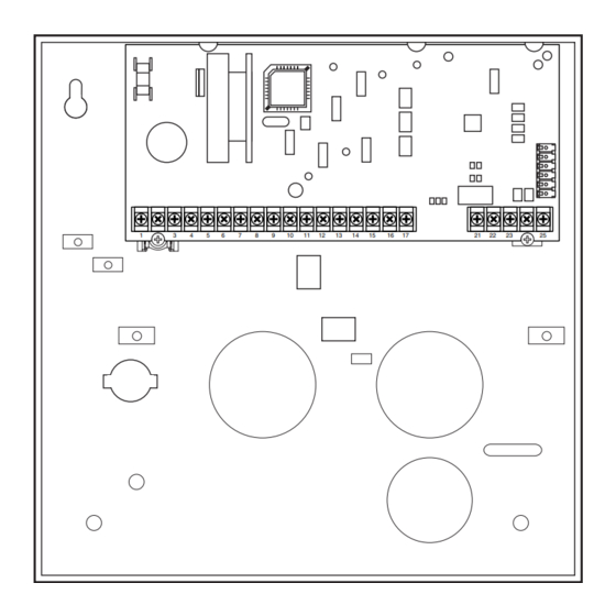
S E C T I O N Mounting and Wiring the Control • • • • • • • • • • • • • • • • • • • • • • • • • • • • • • • • • This section describes the procedures for mounting and wiring this control and its peripheral devices. - Page 10 Installation and Setup Guide V12D-001-V0 Figure 2. Mounting the PC Board...
-
Page 11: Wiring To Keypads
Mounting and Wiring the Control Notes Wiring to Keypads • Typical Fixed-Word Display: Connect keypads to the control’s keypad 6128RF/6148/6150/6150RF/6150V terminals as shown on the Summary of • Typical Alpha Display: 6160/6160V/6160RF/6164 Connections diagram. • The system supports up to 8 keypads, which can Determine wire size using the Wiring Run be assigned to partitions in any combination Chart below. -
Page 12: Sounder (Siren) Connections
Installation and Setup Guide Wiring Run Chart For Devices* Drawing Aux Power From The Control (12V+ & 12V–) TOTAL CURRENT DRAIN OF ALL DEVICES CONNECTED TO A SINGLE WIRE RUN Wire Size 50 mA or less 100 mA 300 mA 500 mA 600 mA 0.6mm O.D. -
Page 13: Wiring The Ac Transformer
Mounting and Wiring the Control Notes Wiring the AC Transformer • Use caution when wiring the Transformer: transformer to the control to guard Connect the Transformer to terminals 1 and 2 on the against blowing the transformer fuse control board. See wiring table at right for wire size to (the fuse is non-replaceable). -
Page 14: Backup Battery
Installation and Setup Guide Notes Backup Battery IMPORTANT: The panel will not power 1. Place the 12-volt backup battery in the cabinet. up initially on battery power only. You 2. After all connections to the control are completed must plug the transformer in first, and and AC mains power has been applied, connect the then connect the battery. -
Page 15: Basic Wired Zones
Mounting and Wiring the Control Basic Wired Zones Notes • EOLR: If the EOLR is not at the end of Normally Open Zones/Normally Open EOLR Zones the loop, the zone is not properly 1. Connect open circuit devices in parallel across the supervised and the system may not loop;... -
Page 16: Smoke Detectors
Installation and Setup Guide Notes Smoke Detectors • • • • Fire Verification (zone type 16): 2-Wire Smoke Detectors The control panel will “verify” a fire 1. Connect up to sixteen 2-wire smoke detectors across alarm by resetting the smoke zone 1 terminals 8 (+) and 9 (-) as shown in the detectors after the first alarm trigger, Summary of Connections diagram. -
Page 17: 4219/4229 Expansion Zones
Mounting and Wiring the Control Notes 4219/4229 Expansion Zones • Supports up to 8 expansion zones (NO or NC) 1. Connect each module to the control’s keypad using 4219/4229 Zone Expander Modules as terminals. follows: 2. Assign the module a device address of 08 •... -
Page 18: 6164 Keypad Expansion Zones
Installation and Setup Guide Notes 6164 Keypad Expansion Zones • Each 6164 keypad supports up to 4 wired 1. Connect each keypad to the control’s keypad expansion EOLR or double-balanced zones terminals. and one relay output. 2. Using the keypad’s program mode, assign the •... -
Page 19: Installing The Rf Receiver
Mounting and Wiring the Control Notes Installing the RF Receiver • The receiver is supervised and a trouble Use one of the following receivers: report is sent (“CHECK 100” displayed) if RF Receiver Number of Zones communication between the panel and 5881ENL up to 8 (including keyfob receiver is interrupted, or if no valid RF... -
Page 20: Installing The Transmitters
Installation and Setup Guide Notes Installing the Transmitters • Refer to the table of compatible devices at 1. To be sure reception of the transmitter's signal the back of this manual. at the proposed mounting location is adequate, • Supervised transmitters †... - Page 21 Mounting and Wiring the Control 8-PIN TRIGGER CONNECTOR 4-WIRE 4146 KEYSWITCH CABLE (ARMED) YELLOW (READY) GREEN WHITE ohms ohms BLACK TAMPER SWITCH (N. C.) BROWN BROWN TYPICAL ZONE ON CONTROL LOCK BOARD SWITCH (N. O.) BLUE BLUE EOLR (use appropriate value) Figure 9.
-
Page 22: Connecting Relay Modules
Installation and Setup Guide Connecting Relay Modules 1. Mount either remotely or in the control panel. Alpha: CHECK xx Wire Expansion 2. Connect to control’s keypad terminals using the FAULT xx Wire Expansion connector harness supplied with the module. TAMPER xx Wire Expansion Use standard 4-conductor twisted cable for long ALARM xx Wire Expansion wiring runs. - Page 23 Mounting and Wiring the Control Figure 10. 4204 Connections to Control (4229 Module and 6164 Keypad is shown in the Expansion Zones sections on page 2-9) 2-15...
-
Page 24: Powerline Carrier Devices
Installation and Setup Guide Notes Powerline Carrier Devices • When using Powerline Carrier devices, you 1. Install up to 4 powerline carrier devices (if no must use a Powerline Carrier Device relays are used) according to the instructions Modulator. It supplies signals from the included with each. -
Page 25: On-Board Triggers
Mounting and Wiring the Control Notes On-Board Triggers • There are two on-board triggers that can Connect field wiring to the desired trigger pin be used to activate output devices. on the 8-pin trigger connector centrally located • These outputs are normally high, and go above the terminal strip. -
Page 26: Phone Line Connections
Installation and Setup Guide Phone Line Connections Notes • If you are using an Audio Alarm Verification Connect incoming phone line and handset wiring (AAV) unit, refer to Audio Alarm to the main terminal block (via an RJ31X jack) as Verification (AAV) section for special shown in the Summary of Connections diagram at wiring connections. -
Page 27: Programming Overview
S E C T I O N Programming Overview • • • • • • • • • • • • • • • • • • • • • • • • • • • • • • • • • About Programming You can program the system at any time, even at the installer's premises prior to the actual installation. -
Page 28: Zones And Partitions
Installation and Setup Guide Zones and Partitions Each protection zone needs to be programmed with various attributes using *56 Zone Programming mode or *58 Expert Programming mode. Refer to those sections for detailed procedures. The system can control three independent areas of protection (known as partitions) for use by independent users, if desired, by simply assigning zones to one of the partitions during zone programming. -
Page 29: Wireless Receiver Transmitters, And Wireless Keys (Keyfobs)
Mounting and Wiring the Control To enable keypads: 1. Set desired address at keypad (refer to keypad’s instructions for setting the address). 2. Use data field program mode to enable keypad addresses, assign a partition, enable sound options in fields *190-*196 as shown in the table above. 3. -
Page 30: Function Keys
Installation and Setup Guide 2. Enable Pager Delay, if desired, in field *166 (delays alarm reporting for ALL pagers). 3. Enable appropriate user open/close pager reports using the user attribute command (master code + [8] + user no. + [#] [5] + [1]). Users that perform actions in their assigned partition will, if enabled, attempt to report to all pagers enabled for open/close reporting in that partition. - Page 31 Mounting and Wiring the Control Zone Type Description • Assign to zones that are used for primary entry and exit. Type 01 • Provides entry delay when zone type is faulted if control is armed in the Entry/Exit Burglary #1 Away, Stay, or Night-Stay modes.
- Page 32 Installation and Setup Guide Zone Type Description • Assign to a zone containing an emergency button, or to a zone containing Type 08 24-hour Auxiliary monitoring devices such as water or temperature sensors. Alarm • Sends a report to the central station and provides an alarm sound at the keypad.
- Page 33 Mounting and Wiring the Control Zone Type Description • Disarms the system when the zone is activated. Type 22: Disarm (BR RF devices only) • User number for button must be assigned. • Can be used on a zone when an output relay action is desired, but with Type 23 * No Alarm Response no accompanying alarm (e.g., lobby door access).
-
Page 34: Mechanics Of Programming
Installation and Setup Guide NOTE: All of the zone types are available for the wireless portion of the system, if used. Mechanics of Programming To program the system from a keypad: • You must use a 2-line Alpha display keypad. •... - Page 35 Mounting and Wiring the Control Loading Factory Defaults/Initializing for Download Press ∗97 while in Program Mode. This resets all data fields to To Load Default Entries the default values shown on the Program Form. Use ∗ 97 only if you wish to return to the original factory-programmed defaults. Press ∗96 while in Program Mode.
- Page 36 Installation and Setup Guide 3-10...
-
Page 37: Data Field Programming
S E C T I O N Data Field Programming • • • • • • • • • • • • • • • • • • • • • • • • • • • • • • • • • About Data Field Programming The following pages list this control’s data fields in numerical order. - Page 38 Installation and Setup Guide FIELD TITLE and DATA ENTRIES EXPLANATION The House ID identifies receivers and wireless RF House ID Code keypads. If a 5827 or 5827BD wireless keypad or 00 = disable all wireless keypad usage 5804BD/5804BDV transmitter is being used, a House 01–31 = House ID for partition 1, 2, 3 ID code must be entered, and the keypad must be set to the same House ID.
-
Page 39: Zone Sounds & Timing
Data Field Programming FIELD TITLE and DATA ENTRIES EXPLANATION If selected, all messages programmed to go to the ECP Contact ID Output for ACM primary telephone line receiver will also be sent (in 0 = not used Contact ID format) to the connected Alternative 1 = use Contact ID output on ECP Communication Media (ACM), such as a 7845i Internet/Intranet Communicator or... -
Page 40: Dialer Programming ( ∗ 40 - ∗ 50)
Installation and Setup Guide FIELD TITLE and DATA ENTRIES EXPLANATION See *35 for explanation. Entry Delay 2 See *35 above for entries. Audible Exit Warning Warning sound consists of slow continuous beeps until last 10 seconds, then it changes to fast beeps. Sound 0 = no;... -
Page 41: Primary Phone No
Data Field Programming FIELD TITLE and DATA ENTRIES EXPLANATION Primary Phone No. If you enter fewer than 30 digits, exit by pressing [∗]. To clear entries from field, press ∗41∗. Enter up to 30 digits. Do not fill unused NOTE: Backup reporting (in which 8 calls are made to spaces. - Page 42 Installation and Setup Guide FIELD TITLE and DATA ENTRIES EXPLANATION Provides delay of “BURGLARY ALARM” report to Burglary Dialer Delay the central station, which allows time for the 0 = no dial delay subscriber to avoid a false alarm transmission. This 1 = 15 seconds delay does not apply to zone type 24 alarms (silent 2 = 30 seconds...
-
Page 43: System Status Report Codes
Data Field Programming System Status Report Codes Zone report codes are programmed using interactive ✱ 56 or ✱ 58 Zone Programming modes, while system status (non-alarm) codes and restore codes are entered in the following data fields. The actual report code digits that you enter depend upon the particular installation, and should agree with the Central Station office receiving the signals. - Page 44 Installation and Setup Guide FIELD TITLE and DATA ENTRIES EXPLANATION Sent when a low-battery condition exists in the Low Battery Report Code system’s battery. 0 = disable; 1-F = see description above ∗59 Sent periodically to test that the communicator and Test Report Code phone lines are operational.
-
Page 45: Miscellaneous System Fields
Data Field Programming Miscellaneous System Fields FIELD TITLE and DATA ENTRIES EXPLANATION Enter the start and end month for summer time, if Summer Time applicable to the region. Start/End Month 0 = Disabled 4 = April 1 = Jan # + 10 = Oct 2 = Feb # + 11 = Nov 3 = Mar... - Page 46 Installation and Setup Guide FIELD TITLE and DATA ENTRIES EXPLANATION Linked Zone Timer: Sets the maximum amount of Linked Zone Verification Timer time in which two linked zones must be tripped in an \Up and About armed system to send an alarm message to the Central Linked Zone Timer Entry: Station.
- Page 47 Data Field Programming FIELD TITLE and DATA ENTRIES EXPLANATION Select the desired option. Exit Options 0 = all intrusion zones must be intact before NOTE: Must be “0” if system uses zone type 82 - arming blockschloss. 1 = All intrusion zones except in exit path (zone list 12) must be intact before arming.
-
Page 48: Download Phone Number
Installation and Setup Guide FIELD TITLE and DATA ENTRIES EXPLANATION Select the desired options by adding the values of each Option Selection desired option. 0 = none 4 = using Audio Alarm Verification (AAV) unit ††“Exit Delay Restart/reset” option allows use of the [∗] 8 = Enable Exit delay restart/reset ††... - Page 49 Data Field Programming FIELD TITLE and DATA ENTRIES EXPLANATION Ring Count For Downloading Refer to the chart below and program this field accordingly. 0 = Disable Monitoring Station initiated phone answer/fax down- downloading Set field ∗ ∗ ∗ ∗ 95 to… module machine loading 1–14 = number of rings before control...
-
Page 50: Pager Programming Fields
Installation and Setup Guide Pager Programming Fields FIELD TITLE and DATA ENTRIES EXPLANATION Pager 1 Phone No. If you enter fewer than 20 digits, exit by pressing [∗] *160 and next field number. To clear entries from this field, Enter up to 20 digits press ∗160∗. -
Page 51: Miscellaneous System Fields
Data Field Programming FIELD TITLE and DATA ENTRIES EXPLANATION Pager 2 Phone No. If you enter fewer than 20 digits, exit by pressing [∗] *163 and next field number. To clear entries from this field, Enter up to 20 digits press ∗163∗. -
Page 52: Siren Options
Installation and Setup Guide FIELD TITLE and DATA ENTRIES EXPLANATION Siren Options Select desired options. *176 Entry 2, if 1: When entry delay is active and an instant Entry 1: 0 = external siren zone is faulted, the siren is delayed 30 seconds and the 1 = self-activated external siren report is delayed 30 seconds, unless field *50 is set for a Entry 2: 0 = disable delay... - Page 53 Data Field Programming FIELD TITLE and DATA ENTRIES EXPLANATION Zone Bypass Limit Select the maximum number of zones that can be *180 bypassed. 0 = unlimited zone bypasses in each partition Each partition individually uses this entry. 1-7 = number of zone bypasses allowed in each partition Use the following table to select the desired options for AC and Clock Display Options...
-
Page 54: Aui Enable
Installation and Setup Guide FIELD TITLE and DATA ENTRIES EXPLANATION Display Options Select the desired keypad display options. *186 Entry 1: If enabled, only the first zone that went into Entry 1: Latch first alarm in the display alarm is displayed. Pressing the READY key will scroll 0 = disable;... -
Page 55: Keypad Programming Fields
Data Field Programming Keypad Programming Fields NOTE: Each keypad must be assigned a unique address. Keypads programmed with the same address will give unpredictable results. FIELD TITLE and DATA ENTRIES EXPLANATION Keypad 2 Device Address 17 Keypad 2 *190 Entry 1: enter the partition in which the keypad is Entry 1 –... - Page 56 Installation and Setup Guide FIELD TITLE and DATA ENTRIES EXPLANATION If enabled, keypads display the exit delay time Exit Time Display Interval *197 remaining after arming the system, with display 0 = no display updates at the interval selected (i.e. if the exit delay is 1-5 = seconds between display refreshing 30 seconds and “2”...
-
Page 57: Menu Mode Programming
S E C T I O N Menu Mode Programming • • • • • • • • • • • • • • • • • • • • • • • • • • • • • • • • • About Zone Programming (∗... -
Page 58: Zone Number
Installation and Setup Guide PROMPT VALID ENTRIES EXPLANATION Enter the zone number that you wish to program. Zone Number Enter Zn Num. Zone 17 has been entered as an example in the wired zones 01-06, (00 = Quit) display at left. aux wired zones 17-24 Enter a report code for zone 91 to enable wireless zones 09-24... - Page 59 Menu Mode Programming PROMPT VALID ENTRIES EXPLANATION Each zone must be assigned to a zone type, which Zone Type (ZT) 17 Zone Type defines the way in which the system responds to 00-24, 77, 82, 90-93 = zone Perimeter faults in that zone. type (see table at right) Enter the Zone Type code from the list below: Note: If 00 is entered, Delete Zone ? will be...
- Page 60 Installation and Setup Guide PROMPT VALID ENTRIES EXPLANATION This prompt is skipped for zones 10-14 if zone- Input Device type (In) 17 INPUT TYPE doubling was enabled at “Hardwire Type” prompt. 2 = AW (Aux wired zone) RF TRANS All of the RF transmitters have one or more 3 = RF (supervised RF unique factory-assigned input (loop) ID codes.
- Page 61 Menu Mode Programming PROMPT VALID ENTRIES EXPLANATION Used only when enrolling wireless transmitters. Serial number Entry 17 INPUT S/N: a. Transmit two open/close sequences. If using a and Loop Number Entry A 0 2 2 - 4 0 6 4 button-type transmitter, press and release the see explanation button twice, but wait about 4 seconds before...
- Page 62 Installation and Setup Guide PROMPT VALID ENTRIES EXPLANATION This prompt will only appear if you answered Confirmation Option XMIT TO CONFIRM “Yes” at the first prompt in this section. Activate the loop input or button ✱ PRESS TO SKIP [∗] to continue The system will enter a confirmation mode so that the operation of the actual programmed input can be confirmed.
-
Page 63: Completing Zone Programming
Menu Mode Programming Completing Zone Programming When you have finished programming all zones, test each zone using the system’s TEST mode. Do not use the Sensor Sniffer Mode for checking wireless transmitting devices, as it will only check for transmission of one zone on a particular transmitter, NOT the zones assigned to each additional loop. -
Page 64: Zone Programming
Installation and Setup Guide PROMPT VALID ENTRIES EXPLANATION A summary screen will appear, showing Summary Screen Zn ZT P RC HW: RT zone 1’s currently programmed (or 01-06, 9-24, 49-64 = zone number 01 09 1 10 default) values. 00 = quit [∗] to continue Enter the zone number being programmed, then press [∗], which... -
Page 65: Serial Number
Menu Mode Programming PROMPT VALID ENTRIES EXPLANATION Manually enter the serial number (found on the Serial number 10 INPUT S/N: transmitter label), by typing digits in the “X” S/N = serial number A X X X - X X X –... -
Page 66: Wireless Key Programming Templates
Installation and Setup Guide PROMPT VALID ENTRIES EXPLANATION If the serial number transmitted matches the Summary Screen Zn ZT P RC In serial number entered, the keypad will beep 3 [∗] to continue 10 03 1 10 RF: 1s times and a summary display will appear, showing the programmed information for that Note that an “s”... - Page 67 Menu Mode Programming PROMPT VALID ENTRIES EXPLANATION 8. The system will search for the highest Start Zone Number ENTER START ZONE available consecutive 4-zone group (the four 00 = QUIT zones in the case of the 5804 and 5804BD), and [∗] to continue display the lowest zone number of the group.
- Page 68 Installation and Setup Guide PROMPT VALID ENTRIES EXPLANATION If the serial number transmitted does not match the serial Not Confirmed Entd A022-4063 number entered, a display similar to the one shown will [∗] to continue Rcvd A022-4064 appear. If the loop number does not match, it will also be displayed.
-
Page 69: About Output Device Programming (*79/*80 Menu Mode)
Menu Mode Programming About Output Device Programming (*79/*80 Menu Mode) Output Devices: The system supports up to 4 relays and/or Powerline Carrier devices (X- 10 devices) plus 2 built-in trigger outputs in any combination. These 6 “outputs” are assigned to system-wide output numbers (01-06 and 17-18). Use *79 Menu Mode to assign output numbers and map them to device addresses. -
Page 70: Unit Number
Installation and Setup Guide Start Output Device Mapping by pressing *79 while in Data Programming Mode. The following prompts are displayed: ∗ ∗ ∗ ∗ 79 Menu Mode PROMPT VALID ENTRIES EXPLANATION This is the logical (or reference) relay number as Device Output Number ENTER OUTPUT NO. -
Page 71: *80 Menu Mode: Defining Output Functions
Menu Mode Programming PROMPT VALID ENTRIES EXPLANATION This is the actual (or physical) relay number with Relay Position XX REL POSITION respect to the Relay Module upon which it is 1-4 = relay position located. For 4204 modules, relay numbers are 1-4. [∗] to continue For 4229 modules, relay numbers are 1-2;... - Page 72 Installation and Setup Guide For example, if you want to pulse a strobe light upon fire alarms on zone 4 using a relay mapped to output number 2 (as programmed in *79 Menu Mode), program the following in *80 Menu Mode: Prompt Entry Output Funct.
-
Page 73: Zone List
Menu Mode Programming “A” If zone list was selected, this screen appears. Otherwise skip to the Zone List 01 Zn List next row. 01-12 = zone list Enter the desired zone list number associated with this output number. [∗] to continue NOTE: Zone lists 09-12 can be used in output definitions if not used for paging or for exit zone definition. -
Page 74: About Zone Lists (∗81 Menu Mode)
Installation and Setup Guide Zone Number If zone number was selected, this screen appears. 01 Enter Zn No. Enter the desired zone number associated with this output number. Press [ ∗ ] to continue. Enter the zone event that will activate this output. 0 = restore;... - Page 75 *81 Menu Mode PROMPT VALID ENTRIES EXPLANATION Zone List Number Enter the Zone List Number to program (or 00 to Zone List No. end these entries). Press [ ∗ ] to advance. 01-12 = zone list number (00 = Quit) [∗] to continue In the following displays, zone list 01 has been selected for programming.
-
Page 76: About Function Key Programming (∗57 Menu Mode)
Installation and Setup Guide About Function Key Programming (∗ ∗ ∗ ∗ 57 Menu Mode) The system provides the ability to program each of the four keypad function keys to perform one of 12 system operations. The end user can then activate the function by simply pressing and holding the programmed key for 2 seconds. - Page 77 Menu Mode Programming PROMPT VALID ENTRIES EXPLANATION Define Key Function Enter the desired function for this key, 00 to 12, Key "A" Func from the options listed. (00 selected for example 00-10 = see list to right Zone 95 display shown at left) [∗] to continue †...
-
Page 78: About Descriptor Programming (*82 Menu Mode)
Installation and Setup Guide About Descriptor Programming (*82 Menu Mode) The system lets you directly enter zone descriptors for each protection zone so when an alarm or trouble occurs in a zone, an appropriate description for that zone's location can be displayed at the keypad. - Page 79 Menu Mode Programming PROMPT VALID ENTRIES EXPLANATION Zone Number After pressing [∗], a cursor will appear at the Z o n e N o . ? second line. Enter the desired zone number. Refer to the Character Chart below. [∗] to continue. Press [#], followed by the 3-digit entry for the first letter you want to display (e.g., # 0 6 5 for “A”).
-
Page 80: Configurable Zone Type Programming (*83 Menu Mode)
Installation and Setup Guide Configurable Zone Type Programming (*83 Menu Mode) Start Configurable Zone Type Programming Mode by pressing ∗ 83 while in Data Programming mode. PROMPT VALID ENTRIES EXPLANATION Zone Type Number Enter the configurable zone type number being E n t e r Z o n e T y p e programmed. -
Page 81: Display Options
Menu Mode Programming PROMPT VALID ENTRIES EXPLANATION Select desired actions for zones assigned to this Alarm/Trouble 9 0 A l m / T r b l P r o c zone type. Processing 0=none Option 2: Select Miscellaneous Fault Delay in 1=Zone type has automatic field *87. -
Page 82: Programming Installer And User Schedules
Installation and Setup Guide Programming Installer and User Schedules The system provides up to 8 schedules, which can be used to control 12 types of system events at pre-defined times. 4 schedules are intended for use by the end-user, and 4 are reserved for the installer. - Page 83 Menu Mode Programming PROMPT VALID ENTRIES EXPLANATION This prompt appears if events “3-8,10” were Partition P A R T I T I O N selected. Otherwise it is skipped. 0 = all partitions Press [*] to continue to the “Start” prompt. 1 = partition 1 2 = partition 2 3 = common partition...
- Page 84 Installation and Setup Guide PROMPT VALID ENTRIES EXPLANATION If selected, the scheduled start and stop times Randomize R A N D O M I Z E will vary within 60 minutes of the “hour” time. 0 = no 0 = N O 1 = Y E S For example, if a schedule is set to start at 1 = yes 6:15pm, it will do so the first time 6:15pm...
-
Page 85: System Communication And Operation
S E C T I O N System Communication and Operation • • • • • • • • • • • • • • • • • • • • • • • • • • • • • • • • • Panel Communication with Central Station This system accommodates several formats for reporting alarms and other system conditions to the Central Station. - Page 86 Installation and Setup Guide The following table describes each format in greater detail. FORMAT TYPE DESCRIPTION 3+1 and 4+1 Comprises a 3- (or 4-) digit subscriber number and a single-digit report Standard Formats code (e.g., Alarm, Trouble, Restore, Open, Close, etc). 3+1 and 4+1 Comprises a 3- (or 4-) digit subscriber number and a two-digit report code.
-
Page 87: Robofon 8 Format
System Communication and Operation Where: SSS or SSSS = Subscriber ID C = Close Code–1st Digit A = Alarm Code–1st digit*** User Number (in hex) Z = Typically Zone Number*–2nd digit Gg = Test Code (1st & 2nd digits) Tt = Trouble Code (1st & 2nd digits) Restore Code (Alarm) Bb = Bypass Code (1st &... -
Page 88: Ademco Contact Id
Installation and Setup Guide Signal flow Receiving equipment Dialing equipment ← Send start char ‘w’ (77h) ← Send message described above → Acknowledge ACK (06h) (Delay greater than 500ms) → Send new start char ‘w’ (77h) ← Send next message if available Acknowledge ACK (06h) …etc •... - Page 89 System Communication and Operation TABLE OF CONTACT ID EVENT CODES Code Definition Code Definition Fire Alarm RF Sensor Low-battery Duress Clean Me (ESL smoke detectors only) Alarm, 24-hour Silent Disarmed, Armed AWAY, Alarm, 24-hour Audible Armed MAXIMUM Alarm, Perimeter Scheduled Arm/Disarm AWAY Alarm, Interior Cancel by User Alarm, Entry/Exit...
-
Page 90: Security Codes
Installation and Setup Guide Security Codes The system supports up to 16 security codes, which can each be assigned one of 5 authority levels. The authority level determines the functions each code can perform as follows: Authority Levels (authority levels can be assigned to users 3-49 only; users 1 and 2 cannot be changed) Level User No. -
Page 91: Keypad Functions
System Communication and Operation Assigning Attributes: Master code + [8] + 2-digit user no. + [#] [attribute no.] + value Attributes: Values 1 = Authority Level 0-4 (see Authority Level table above) 2 = Access Group 0-8 (0 = not assigned to a group) 3 = Active Partition(s) 1, 2, 3 for this user;... - Page 92 Installation and Setup Guide Keypad Commands (cont’d.) Arming Away Enter code + AWAY [2] or simply press appropriate lettered key on the keypads (see “Single-Button Arming” above). If the “Auto-Stay Arm” feature is enabled and the entry/exit door is not opened and closed within the programmed exit delay time, the system will automatically arm in STAY mode if armed from a wired keypad (non-RF device).
-
Page 93: Panic Keys
System Communication and Operation Panic Keys There are three Panic keys (A, B, and C) that, if programmed, can be used to manually initiate alarms and send a report to the central station. Each key can be programmed for 24- hour Silent, 24-hour Audible, Fire, or Personal Emergency responses. -
Page 94: Setting/Adjusting The Real-Time Clock
Installation and Setup Guide • Press [∗] to save the new number. The following prompt appears: FM Repeat • Enter the number of times, 1-7, the tones should be repeated during the follow-me phone call. Setting/Adjusting the Real-Time Clock The real-time clock is used to time-stamp events recorded in the event log and for scheduling mode. -
Page 95: Various System Trouble Displays
System Communication and Operation Various System Trouble Displays Alpha Display Fixed Disp. Meaning Appears if an exit or interior zone contained a fault during closing at CANCELED ALARM the time the Exit Delay ended (e.g., exit door left open and the zone was not auto-bypassed), but the system was disarmed during the Entry Delay time. - Page 96 Installation and Setup Guide Various System Trouble Displays (cont’d.) no display no display Power Failure If there is no keypad display at all and the LEDs are unlit, operating power (AC and battery) for the system has stopped and the system is inoperative.
-
Page 97: Testing The System
S E C T I O N Testing the System • • • • • • • • • • • • • • • • • • • • • • • • • • • • • • • • • About Test Procedures After the installation is complete, you should perform the following tests: System Test: ....Checks that all zones have been installed properly. -
Page 98: Go/No Go Test Mode
Installation and Setup Guide Checking Zones Using One-Man Walk Test (Sniffer Mode) Use this mode to test all zones (wired and wireless) that have been programmed. Make sure all partitions are disarmed before trying to enter this mode, since this is a system-wide command. -
Page 99: Dialer Communication Test
Testing the System Dialer Communication Test 1. Enter Installer Code + 5 [ TEST ], then press “1” at the prompt to start the Dialer Test. 1=DIAL, 0=WALK (no special display on Fixed-Word keypads) The following will be displayed (accompanied by 2 beeps) if test is successful: PHONE OKAY (“Cd”... - Page 100 Installation and Setup Guide...
-
Page 101: Specifications & Accessories
S E C T I O N Specifications & Accessories • • • • • • • • • • • • • • • • • • • • • • • • • • • • • • • • • SECURITY CONTROL 1. -
Page 102: Compatible Devices
Installation and Setup Guide COMPATIBLE DEVICES Keypads: 6128RF, 6148, 6150, 6150RF, 6160RF, 6160V, 6164 Wireless Receivers: 5881ENL/5882L: accepts up to 8 transmitters 5881ENM/5882M: accepts up to 16 transmitters 5881ENH/5882H: accepts up to system maximum transmitters 5882EU: accepts up to system maximum transmitters 5882EUH: accepts up to system maximum transmitters 5883M: accepts up to 16 transmitters 5883H: accepts up to system maximum transmitters... -
Page 103: 5800 Series Transmitter Input Loop Identification
Specifications and Accessories 5800 Series Transmitter Input Loop Identification All of the transmitters illustrated below have one or more unique factory assigned input (loop) ID codes. Each of the input loops requires its own programming zone (e.g., a 5804's four inputs require four programming zones). - Page 104 Installation and Setup Guide Compatible 5800 Series Transmitters Table (cont’d.) • House ID must be set. 5804BD Bi-Directional BR Only • Requires 5800TM Transmitter Module or 5883 Wireless Key Transceiver. • Can indicate system status via its 2 LEDs and built-in sounder.
- Page 105 Specifications and Accessories Compatible 5800 Series Transmitters Table (cont’d.) Model Product Input Type Description • Can be used to turn the burglary protection on 5827 Wireless Keypad Uses House ID only and off. • Features the same built-in panic functions as wired keypads.
- Page 106 Installation and Setup Guide...
-
Page 107: Limitations And Warranty
S E C T I O N Limitations and Warranty • • • • • • • • • • • • • • • • • • • • • • • • • • • • • • • • • WARNING THE LIMITATIONS OF THIS ALARM SYSTEM While this System is an advanced design security system, it does not offer guaranteed protection against burglary, fire or... -
Page 108: Limited Warranty
LIMITED WARRANTY Honeywell International Inc., acting through its Security & Custom Electronics business ("Seller") 165 Eileen Way, Syosset, New York 11791, warrants its product(s) to be in conformance with its own plans and specifications and to be free from defects in materials and workmanship under normal use and service for 24 months from the date stamp control on the product(s) or, for product(s) not having a manufacturer’s date stamp, for 12 months from date of... -
Page 109: Index
– INDEX – 1321..............2-5 Bell Supervision Jumper........2-4 1321X10 ...........2-16, 2-17 Bypassing Zones..........6-8 24-Hour Audible Alarm.........3-5 Cabinet..............2-1 24-Hour Auxiliary Alarm ........3-6 Character (ASCII) Chart ........5-23 24-Hour Silent Alarm..........3-5 Character List............ 5-23 2-Wire Smoke Detectors........2-8 Charging Voltage..........8-1 3+1 and 4+1 Standard Formats ......6-2 Chime By Zone............ - Page 110 Index IBM Personal Computer........3-1 Remote Keypads..........1-2 Input Device Type ........5-8, 8-3, 8-5 Report Code....3-3, 4-7, 4-8, 4-11, 5-3, 5-8, 6-1 Installer Code........3-9, 4-1, 7-1, 7-3 Report Code Formats .......... 6-1 Interior Follower ..........3-5, 5-17 Reports In Armed Period ........4-12 Interior w/Delay...........3-6, 5-17 response time........
- Page 111 Figure 17. Summary of Connections...
- Page 112 165 Eileen Way, Syosset, New York 11791 Copyright © 2005 Honeywell International Inc. www.honeywell.com/security ÊK10022V1nŠ K10022V1 4/05 Rev. A...