Table of Contents
Advertisement
Quick Links
V V V V
I I I I
S S S S
T T T T
A A A A
- - - -
1 1 1 1
2 2 2 2
8 8 8 8
B B B B
P P P P
E E E E
N N N N
V V V V
I I I I
S S S S
T T T T
A A A A
- - - -
1 1 1 1
2 2 2 2
8 8 8 8
B B B B
P P P P
E E E E
N N N N
Commercial Burglary
Partitioned Security System
With Scheduling
Installation and Setup Guide
800-05855 2/10 Rev B
Advertisement
Table of Contents

Related Manuals for Honeywell VISTA-128BPEN


Summary of Contents for Honeywell VISTA-128BPEN
- Page 1 V V V V I I I I S S S S T T T T A A A A - - - - 1 1 1 1 2 2 2 2 8 8 8 8 B B B B P P P P E E E E N N N N...
-
Page 3: Table Of Contents
• • • • • • • • • • • • • • • • • • • • • • • • • • • • • • • • • • • • • • • • • • • • • • • • • List of Figures................................vi Conventions Used in This Manual........................vii SECTION 1 ................................1-1 General Description ..............................1-1 About the VISTA-128BPEN..............................1-1 Features .....................................1-1 SECTION 2 ................................2-1 Partitioning and Panel Linking..........................2-1 Theory of Partitioning .................................2-1 Setting-Up a Partitioned System ............................2-1... - Page 4 Table of Contents SECTION 5 ................................5-1 Data Field Descriptions ............................5-1 About Data Field Programming ............................5-1 Programming Data Fields..............................5-1 SECTION 6 ................................6-1 Scheduling Options ..............................6-1 Time Window Definitions..............................6-2 Open/Close Schedules Definitions .............................6-3 Scheduling Menu Mode..............................6-4 Time Windows..................................6-5 Daily Open/Close Schedules..............................6-6 Holiday Schedules................................6-6 Time-Driven Events................................6-7 Limitation of Access Schedules............................6-11 Temporary Schedules ..............................6-12...
- Page 5 Table of Contents Specifications ............................... C-1 APPENDIX D ..............................D-1 Contact ID Event Codes............................D-1 TABLE OF CONTACT ID EVENT CODES ........................D-1 Event Log Alpha Descriptors............................. D-1 Index ................................Index-1 THE LIMITATIONS OF THIS ALARM SYSTEM HONEYWELL LIMITED WARRANTY...
-
Page 6: List Of Figures
Figure 3-13: Wiring a Normally Closed Loop for Tamper Supervision ................3-10 Figure 3-14: Wiring a Normally Open Loop for Tamper Supervision.................3-10 Figure 3-15: Polling Loop Connections to the VISTA-128BPEN..................3-12 Figure 3-16: Polling Loop Connections Using One 4297 Extender Module ................3-13 Figure 3-17: Polling Loop Connections Using Multiple Extender Modules ................3-13... -
Page 7: Conventions Used In This Manual
Conventions Used in This Manual • • • • • • • • • • • • • • • • • • • • • • • • • • • • • • • • • • • • • • • • • • • • • • • • • Before you begin using this manual, it is important that you understand the meaning of the following symbols (icons). - Page 8 SIA CP-01 Quick Reference Chart The minimum required system for SIA CP-01 is a UL Listed Control, Keypad and Bell. Item Feature Range Shipping Default Requirement* Entry Delay # 1 02 – 15 multiplied by 15 30 Seconds` At least 30 Seconds ** seconds 00 = 240 sec (4 minutes)
- Page 9 Item Feature Range Shipping Default Requirement* Zone Abort Window (for 0 = no abort window 1 = yes Yes (all non-fire Programming non-fire zones) zones) 1 = yes, use abort (Abort window according to *88 Window selection Enable) Zone Swinger Suppression 0 = no suppression Yes (enabled) Yes (enabled (all...
-
Page 11: Section 1
An access control system by using either the ADEMCO PassPoint system (via the VISTA Gateway Module) or a VistaKey module (via the polling loop) The access control function is not Listed for use with the VISTA-128BPEN Control Panel in a UL installation. The system supports either the VistaKey or the VISTA Gateway Module, not both. - Page 12 #70 Relay Command Mode. • Supports the Honeywell 4286 VIP Module, which allows access to the system from either a remote location or on the premises The VIP Module is not Listed for use with the VISTA-128BPEN Control Panel in a UL installation.
- Page 13 128 zones, as well as openings and closings for all 150 users. This requires central stations to be equipped with the MX8000 receiver to fully support all new VISTA-128BPEN report codes. If you need to update your MX8000 receiver, contact your distributor.
- Page 14 Vista-128BPEN Installation and Setup Guide • Provides trigger outputs, which may interface with Communicator equipment or other devices such as keyswitch LEDs, or printer. • Provides an RS232 input for serial data. This is useful for interfacing the system with Automation software.
-
Page 15: Section 2
S E C T I O N Partitioning and Panel Linking • • • • • • • • • • • • • • • • • • • • • • • • • • • • • • • • • • • • • • • • • • • • • • • • • Theory of Partitioning This system provides the ability to arm and disarm up Zones... - Page 16 Vista-128BPEN Installation and Setup Guide The common lobby cannot be armed unless every NOTE: In the tables below, the notations in partition selected to affect the lobby is armed. parentheses ( ) indicate the current status of the other partition when the user takes action.
-
Page 17: Master Keypad Setup And Operation
WHSE DISARMED HIT ✴ FOR FAULTS Panel Linking Up to eight VISTA-128BPEN control panels may be networked, enabling a user to control the features of all Panel Linking is not permitted in UL control panels from a single location. The panel linking installations. - Page 18 Vista-128BPEN Installation and Setup Guide other control panels) in any of three different modes: Panel Link Module Supervision Single-Partition, Single-Panel Mode; Multi-Partition, The Panel Link Module can be supervised for its Multi-Panel Mode; Multi-Panel View Mode. These connection to the control panel. The module’s modes are described later in this section.
- Page 19 Section 2 – Partitioning and Panel Linking Single-Partition Single-Panel Mode To access the Single-Partition, Single Panel mode, perform the following steps: Step Action Enter User Code (for users 001-050) + [#] + [86]. Enter the panel ID number (01-08) of the panel you want to link to. Enter the partition number of the panel.
- Page 20 When performing either a STAY or INSTANT arm command, the system always arms in mode 1 (see the VISTA-128BPEN User Guide for a detailed explanation of the STAY and INSTANT arming modes). The user cannot execute another panel linking mode. In order to perform another panel linking mode or to access a different remote panel, the user must first exit this mode (return to the original control panel).
-
Page 21: Section 3
S E C T I O N Installing the Control • • • • • • • • • • • • • • • • • • • • • • • • • • • • • • • • • • • • • • • • • • • • • • • • • This section describes the procedures for mounting and wiring the control panel and all the peripheral devices. -
Page 22: Mercantile Safe And Vault Listing Guidelines
Vista-128BPEN Installation and Setup Guide • All unused knockouts must be plugged using the disc plugs and carriage bolts (supplied), as indicated in the diagram below. • Fasten the cabinet door to the cabinet backbox using the 18 one-inch-long Phillips-head screws (supplied) after all wiring, programming, and checkout procedures have been completed. -
Page 23: Installing The Keypads
Installing the Control Installing the Keypads Up to 31 addressable keypads (addresses 00-30) may be used (you may need to use an auxiliary power supply if the 750mA aux. output is exceeded). NOTE: Refer to the Alpha Vocabulary list found in the #93 Menu Mode in the Programming Guide for list of the words annunciated by the 6160V. -
Page 24: Installing External Sounders
KEYPAD Figure 3-5: Using A Supplementary Power Supply Installing External Sounders The VISTA-128BPEN provides a bell circuit output for operating fire and burglary alarm notification appliances. The alarm output is rated as follows: 10VDC – 14VDC, 1.7A max., power-limited. •... -
Page 25: Figure 3-6: Wiring Polarized Fire Devices
Alarm Output Supervision When supervision is enabled, the VISTA-128BPEN monitors the alarm output wiring for open and short circuit faults while the output is inactive. The system provides a trouble indication (Zone 970) when an open occurs; or when a short occurs between the Bell (+) and Bell (-) terminal wiring, or between the Bell (+) terminal wiring and earth ground. -
Page 26: Telephone Line Connections
150 users. This requires central stations to be equipped with the MX8000 receiver to fully support all new VISTA-128BPEN report codes. If you need to update your MX8000 receiver, contact your distributor. -
Page 27: Wiring Burglary, Panic And Smoke Detector Devices To Zones 1-9
Installing the Control Reporting Formats The system supports the following formats: ADEMCO Low Speed 3+1; 4+1; 4+2; Sescoa/Radionics 3+1; 4+1; 4+2; ADEMCO 4+2 Express; ADEMCO High Speed; ADEMCO Contact ID Incoming Handset Telco Line TERMINALS EARTH GROUND ON CONTROL INCOMING TELCO LINE DIRECT CONNECT CORD... -
Page 28: Figure 3-10: 2-Wire Smoke Detector On Zone 1
System Sensor 1100 Photoelectric w/B110LP base System Sensor 2151 These smoke detectors are UL Listed for use with the VISTA-128BPEN and are the only 2-wire smoke detectors that may be used. Wiring 2-Wire Smoke Detectors to Zone 1 2K EOL resistors must be used on fire zones and must be connected across the loop wires of each zone at the last detector. -
Page 29: Figure 3-11: 4-Wire Smoke Detectors
Installing the Control Power to 4-wire smoke detectors must be supervised with an EOL device (use a System Sensor EOLR-1 EOL relay module connected as shown in Figure 3-11 ). To wire 4-wire smoke detectors to zones 1-8, perform the following steps: Step Action Select 4-wire smoke detectors (see list of compatible detectors shown previously). -
Page 30: Figure 3-13: Wiring A Normally Closed Loop For Tamper Supervision
Vista-128BPEN Installation and Setup Guide • The alarm current provided by zone 8 supports only one glassbreak detector in the alarmed state. • Do not use other contacts when using glassbreak detectors on zone 8. Other contacts may prevent proper glassbreak detector operation. -
Page 31: Installing V-Plex Devices
Installing the Control Installing V-PLEX Devices The polling loop provides both power and data to the V-Plex devices, and is constantly monitoring the status of all zones enabled on the loop. The maximum current draw of all devices on the polling loop cannot total more than 128mA (unless the system uses a 4297 Polling Loop Extender Module). - Page 32 Vista-128BPEN Installation and Setup Guide IMPORTANT NOTE: If the installation needs to exceed or deviate from these parameters, refer to the application note on the Honeywell website for additional polling loop wiring configurations. To access the application note: Go to the honeywell.com/security website Click the Honeywell Security &...
-
Page 33: Figure 3-16: Polling Loop Connections Using One 4297 Extender Module
Installing the Control Be sure to include the total current drawn on the polling loop when figuring the total auxiliary load on the panel’s power supply. INPUT POLLING LOOP EXTENSION POLLING LOOP 4297 CONTROL PANEL OTHER RPMS EXTENSION POLLING LOOP LIMITS = SAME AS INPUT LOOP INPUT LOOP LIMITS: •... -
Page 34: Figure 3-18: Installing The 5881Enhc With Tamper Protection
Vista-128BPEN Installation and Setup Guide A response type (05 Day/Night) must be programmed for zones 990 (1 receiver) and 988 (2 receiver) for UL installations. • The 5881ENHC receiver contains front and back tampers that permit its use in commercial burglary installations. - Page 35 Installing the Control To install the 5881ENHC RF receiver, perform the following steps: Step Action Mount the receiver, following the advisories stated previously. Set the DIP switches in the receiver for the address (01-07). See Figure 3-19. Make sure the address setting is not being used by another device (keypad, relay module, etc.). If installing a 5881ENHC, install a flat-head screw (supplied) in the case tamper tab as shown in Figure 3-18.
- Page 36 Vista-128BPEN Installation and Setup Guide House ID Sniffer Mode This mode applies only if you are using a wireless keypad (e.g., 5827) or bi-directional devices (e.g., 5804BD). Use the House ID Sniffer mode to make sure you do not choose a House ID that is in use in a nearby system. The House ID must be programmed for the receiver in Device Programming in the #93 Menu Mode.
- Page 37 Installing the Control Button-type transmitters (e.g., 5801, 5802, 5802CP and 5803) should be periodically tested, as these transmitters do not send supervisory check-in signals. To test the transmitters using the Transmitter ID Sniffer mode and the Go/NoGo Test Mode, see SECTION 10: Testing the System for the procedures.
-
Page 38: Installing Output Devices
Installing Output Devices The VISTA-128BPEN support up to 96 outputs. Each device must be programmed as to how to act (ACTION), when to activate (START), and when to deactivate (STOP). The 4204, 4204CF, FSA-8, FSA-24, 4101SN and/or X-10 devices may be used as output devices. -
Page 39: Installing The Ground Start Module
Installing the Control Installing FSA ModulesThe 8-zone LED Fire System Annunciator FSA-8 and 24-zone LED Fire System Annunciator FSA-24 enable a fire response unit to identify quickly the point/zone of a fire. These indicators may be used for other functions as well, such as status indication. A maximum of four FSA modules, in any combination, can be supported. The FSA module will not operate until the device address you have set the DIP switches for is enabled in the control’s Device Programming in the #93 Menu Mode . -
Page 40: Installing A Remote Keyswitch
Figure 3-23: Ground Start Module Connections Installing a Remote Keyswitch A UL-Listed remote keyswitch, such as the Honeywell 4146, can be used for remote arming/disarming of the burglary portion of the system and for silencing alarms. The keyswitch can operate in only one particular partition. -
Page 41: Smoke Detector Reset
To install the Honeywell 4146 keyswitch, perform the following steps: Step Action Connect the Honeywell 4146 to the panel as shown in Figure 3-24. If you are using the tamper, make sure it is connected to a zone. TO AUX POWER... -
Page 42: Installing The Va8200 Panel Link Module
Installing the VA8200 Panel Link Module The VA8200 Panel Link Module (PLM) connects to the keypad (ECP) terminals on the VISTA-128BPEN and also connects to other PLMs via the RS-485 bus (3-wire twisted cable run). Figure 3-26 is a block diagram of a panel linking setup using three control panels. -
Page 43: Communicator Connected To The J7 Triggers
Communicator Connected to the J7 Triggers These triggers may be used to trip auxiliary alarm signaling equipment such as Honeywell’s 7845GSM, 7845iGSM, and 7847i, Communicators. The triggers are common to all partitions and must be enabled for each partition (field 2✳20). -
Page 44: Figure 3-28: Wiring Communicator To Keypad Terminals
11 is not, zone 10 will report via the Communicator, but Zone 11 will not. Reports are transmitted from the VISTA-128BPEN to the Communicator on a “first in/first out” basis. If events occur at the same time, they are transmitted in order of priority. The priority from most to least important is : Fire Alarms, Panic Alarms, Burglary Alarms, Fire Troubles, Non-Fire Troubles, Bypasses, Openings/Closings, Test messages, and all other types of reports. -
Page 45: Access Control Using Vistakey
All configurable options for each VistaKey are accomplished via software, firmware, and nonvolatile memory, except the access point zone number (1-15), which is set via a user-friendly, 16-position rotary switch. • The addition and removal of VistaKey modules from the system is easily accomplished via the VISTA-128BPEN keypad. •... -
Page 46: Figure 3-29: Wiring The Vistakey
Local +12V or +24V supply lead to the N/C relay terminal 11 (if a mag lock is being used), OR to the N/O relay terminal 10 (if a door strike is being used). Connect the (–) polling loop and (+) polling loop leads (from the VISTA-128BPEN) to terminals 4 and 3, respectively. -
Page 47: Access Control Using The Passpoint Access Control System
Access Control Using the PassPoint Access Control System The VISTA-128BPEN interfaces with the PassPoint ACS via the VISTA Gateway Module (VGM). The VGM is connected between the ECP bus (keypad terminals) of the control and the network bus of the PassPoint ACS. -
Page 48: Installing The 4286 Vip Module
Vista-128BPEN Installation and Setup Guide J8 CONNECTOR 4142TR CABLE (SUPPLIED WITH 4100SM) 4100SM SERIAL MODULE To TB6 Aux. Power (+) + PWR (25mA current draw) To TB7 Aux. Power (-) - (GND) not used not used not used BLUE WHITE... - Page 49 Installing the Control The 4286 VIP Module is not permitted in UL installations. Detailed operating instructions for phone access to the security system are provided with the VIP Module. The 4286 VIP Module features: • Allows the user to receive synthesized voice messages over the phone regarding the status of the security system. •...
-
Page 50: Installing The Audio Alarm Verification Module
Follow.” It is the only format capable of uniquely reporting all 128 zones, as well as openings and closings for all 150 users. This requires central stations to be equipped with the MX8000 receiver to fully support all new VISTA-128BPEN report codes. If you need to update your MX8000 receiver, contact your distributor. •... -
Page 51: Figure 3-34: Uvs Connections To The Control Panel
Installing the Control If the phone plug is disconnected from the control, the premise’s phones will not operate. NOTES: • When the AAV indicates that the audio alarm verification session is completed, all keypad sounds are restored. Sirens are restored if the alarm timeout period has not expired. •... -
Page 52: Connecting The Transformer
Vista-128BPEN Installation and Setup Guide Connecting the Transformer This product uses the 1361 transformer (1361CN in Canada). If you are using X-10 devices, the 1361X10 transformer interface must be used instead of the regular 1361 transformer. The 1361X10 supplies the control panel with AC, and also sends control pulses through the premises’... -
Page 53: Panel Earth Ground Connections
Installing the Control TRANSFORMER/X10 INTERFACE J8 CONNECTOR 1 2 3 4 5 6 7 8 9 9-PIN CONNECTOR ON CONTROL PANEL 4142TR CABLE Sync Signal Output Common Data PINS (1,2,5,7,9) NOT USED YEL/WHT (SYNC) GREEN (DATA) TERMINALS ON CONTROL BLUE (COM) BOARD 1361X10-002-V1 Figure 3-36: 1361X10 Transformer Connections... - Page 54 Vista-128BPEN Installation and Setup Guide In Table 2, enter devices used on Auxiliary Power. Calculate standby and alarm currents, then add to get Auxiliary Power current subtotal. Table 2: Auxiliary Power Current Load Total Current Device Device Current X Standby...
-
Page 55: Determining The Size Of The Standby Battery
Installing the Control In Table 4, enter the total calculated subtotals of all listed outputs from Tables 1 through 3, then add to get the combined current. Table 4: Total VISTA-128BPEN Current Load Total Current Standby Alarm Polling Loop Subtotal (see Table 1) Aux. - Page 56 10 minutes every 4 hours, beginning 4 hours after exiting Programming mode. In addition, entry into the Test mode initiates a battery test. The VISTA-128BPEN also runs a 5-second battery test every 60 seconds to check if the battery is connected.
- Page 57 Installing the Control Connect the battery, referring to Figure 3-37. NOTE: WHEN CONNECTING BATTERIES IN PARALLEL: BATTERY TABS USE THE 2nd PAIR OF BATTERY - USE BATTERIES FROM THE SAME MANUFACTURER AND TABS AND THE 2nd PAIR OF WITH THE SAME VOLTAGE AND CAPACITY RATING. BATTERY HARNESSES (NOT - USE BATTERIES WITH APPROXIMATELY SAME AGE AND SUPPLIED) TO CONNECT ONE...
- Page 58 Vista-128BPEN Installation and Setup Guide 3-38...
-
Page 59: Section 4
S E C T I O N Programming • • • • • • • • • • • • • • • • • • • • • • • • • • • • • • • • • • • • • • • • • • • • • • • • • Program Modes There are two programming modes for the VISTA- The factory-loaded defaults (✳97) enable... -
Page 60: #93 Menu Mode Programming
Press 0 (NO) or 1 (YES) in response to the displayed menu selection. Pressing 0 will display the next choice in sequence. Below is a list of the main menus. For details refer to the VISTA-128BPEN Programming Guide. - Page 61 MAIN MENU OPTIONS For programming the following: ZONE PROG? • • Zone Number Input Device Type for zone (whether RF, polling 1 = YES 0 = NO loop, etc.) • Zone Response Type • Enrolling serial numbers of 5800 Series transmitters •...
-
Page 62: Zone Number Designations
Quits Menu Mode and goes back to Data Field Programming Mode, if entered at first prompt of each main menu option. Zone Number Designations The VISTA-128BPEN supports up to 128 zones of Zone Index hardwire, polling loop and/or wireless protection, The zones are designated as follows: distributed among up to eight partitions. -
Page 63: Zone Response Type Definitions
Section 4 – Programming Communication Defaults for Zones ZONE # ZONE # ZONE # 601-632 800-830 992 (DURESS) ALARM RST. TROUBLE TRBLE. RST BYPASS BYP. RST. Zone Response Type Definitions Each zone must be assigned a zone type, which defines the panel is armed in the INSTANT or MAXIMUM the way in which the system responds to faults in that mode, no entry delay is provided. - Page 64 Assign this zone type to a zone an access point entry relay can be assigned to an access Emergency button or one containing monitoring devices control relay (controlled by the VISTA-128BPEN), ECP such as water sensors or temperature sensors. relay (4204), or to the access control system independent of the control panel.
-
Page 65: Zone Input Type Definitions
Type 06 Serial Number Polling Loop (SL) This input type operates in the same manner as other Select for polling loop devices with a built-in serial VISTA-128BPEN alarm panel zones and is provided so number. that a zone in the proximity of the VistaKey can be... -
Page 66: Programming For Panel Linking
The programming is If the PassPoint ACS has uncommitted zones, these accomplished in field 1∗35 for the following events: may be used by the VISTA-128BPEN as hardwired • ACS Troubles - To enable or disable ACS trouble zones. - Page 67 Access Control An RF transmitter (5816) can be used with a remote The VISTA-128BPEN can be used for access control switch to provide exit in case of a fire alarm using a without interfacing to PassPoint ACS or VistaKey. A PassPoint event action.
-
Page 68: Programming For Ecp Communicator
Vista-128BPEN Installation and Setup Guide Programming for ECP Communicator • • Field ✳57: Select the initial reporting destination Program the Communicator in Device Programming in the #93 Menu Mode Programming. for messages. • Field ✳56: Selects the time the panel should wait •... -
Page 69: Section 5
1 = enable Quick Exit is initiated by entering [#] + [9]. This restarts the exit delay. All rules of exit apply, including exit error logic. Quick Exit is not permitted for use with the VISTA-128BPEN Control Panel in a UL installation. - Page 70 Vista-128BPEN Installation and Setup Guide FIELD TITLE and DATA ENTRIES EXPLANATION Entry Delay #1 (partition-specific) Entry delay defines the delay time that allows users to re-enter the premises through a door that has been programmed as an entry delay door and disarm Enter 02-15 multiplied by 15 seconds.
- Page 71 Section 5 – Data Field Descriptions FIELD TITLE and DATA ENTRIES EXPLANATION If enabled, randomizes AC loss reporting between 10 and 40 min. after an Randomize AC Loss Report actual AC loss. 0 = disable 1 = enable If disabled, AC loss reporting about 2 minutes after actual AC loss. Selecting this option helps prevent an overload of AC loss messages at the central station during a community blackout.
- Page 72 Vista-128BPEN Installation and Setup Guide FIELD TITLE and DATA ENTRIES EXPLANATION Enter a 3- or 4-digit (depending on report format) primary subscriber account Primary Subscriber’s Account number. Each number requires a 2-digit entry so as to allow entry of Number (partition-specific) hexadecimal digits (B-F).
- Page 73 Section 5 – Data Field Descriptions FIELD TITLE and DATA ENTRIES EXPLANATION If enabled, the system waits for true dial tone. If no dial tone is detected, Dial Tone Detection control dials at end of pause programmed in field *42. 0 = disable 1 = enable If disabled, the system pauses for seconds entered in field *42, then dials.
- Page 74 Vista-128BPEN Installation and Setup Guide FIELD TITLE and DATA ENTRIES EXPLANATION If enabled, the system automatically calls the downloader at programmed Unattended Mode intervals. 0 = disable 1 = enable NOTE: The following fields must be programmed first: primary subscriber account number –...
- Page 75 Section 5 – Data Field Descriptions FIELD TITLE and DATA ENTRIES EXPLANATION The Abort Window exists for all non-fire zones. All non-fire alarm reports are Abort Window (partition-specific) NOT transmitted to the central station, if the code sequence is entered 1 = 15 seconds within the Abort Window.
- Page 76 Vista-128BPEN Installation and Setup Guide FIELD TITLE and DATA ENTRIES EXPLANATION If enabled, when the panel is armed, the normal exit delay begins. After the Exit Delay Reset 1*21 user exits, closes the door and then re-enters the premises, the exit delay 0 = disable time is reset to the programmed value.
- Page 77 Section 5 – Data Field Descriptions FIELD TITLE and DATA ENTRIES EXPLANATION Select the first pair of cross zones, which must both be faulted within a 5- Cross Zoning Pair One 1*22 minute period to cause an alarm. Enter 001-128 Enter 000,000 to disable Must be 000,000 for UL installations.
- Page 78 Vista-128BPEN Installation and Setup Guide FIELD TITLE and DATA ENTRIES EXPLANATION There are six entries for this field as follows: Trace, Trouble, Not Used, Access Control Dialer Enables 1*35 Bypass, System and Alarm. 0 = disable 1 = enable If Trace is enabled, access grant/denial events sent to the central station.
- Page 79 Section 5 – Data Field Descriptions FIELD TITLE and DATA ENTRIES EXPLANATION If enabled, the system arms/disarms in accordance with the button’s user’s Enable 5800 RF Button Global 1*57 global arming settings. 0 = disable 1 = enable If enabled, allows the RF button user to force a bypass of all faulted zones Enable 5800 RF Button Force 1*58 when arming the system.
- Page 80 Vista-128BPEN Installation and Setup Guide FIELD TITLE and DATA ENTRIES EXPLANATION When enabled automatically transfers data of the RS232 output. Log Faults & Restores 1*80 0 = disable Home Control Automation is not allowed in UL installations. 1 = enable Number of Partitions Enter the number of partitions used in the system.
- Page 81 Section 5 – Data Field Descriptions FIELD TITLE and DATA ENTRIES EXPLANATION If enabled, allows the system to be disarmed outside the programmed disarm Allow Disarm Outside Window if 2*11 (opening) window if an alarm has occurred. Otherwise disarming is allowed Alarm Occurs only during the disarm window.
- Page 82 Vista-128BPEN Installation and Setup Guide 5-14...
-
Page 83: Section 6
S E C T I O N Scheduling Options • • • • • • • • • • • • • • • • • • • • • • • • • • • • • • • • • • • • • • • • • • • • • • • • • Scheduling is currently not approved for ULC applications. -
Page 84: Time Window Definitions
Vista-128BPEN Installation and Setup Guide Exception Reports devices on and off. The Time-Driven events can be activated at different times in relation to a time This option allows the reporting of openings and window: closings to the central station only if the arming and •... -
Page 85: Open/Close Schedules Definitions
Section 6 – Scheduling Options Open/Close Schedules Definitions General Additional Schedules The open/close scheduling is controlled by one of three Additional opening and closing schedules can be schedules. Each schedule consists of one time window programmed using the Time-Driven Event for openings and one time window for closings. -
Page 86: Scheduling Menu Mode
Vista-128BPEN Installation and Setup Guide Scheduling Menu Mode The #80 Scheduling Menu Mode is used to program Steps to Program Scheduling Options most of the scheduling and timed-event options. Enter Installer Code + [#] + [8] + [0] from the normal This section contains examples of the operating mode. -
Page 87: Time Windows
Section 6 – Scheduling Options PROMPT EXPLANATION Enter 1 to program timed events for relay outputs, additional schedules, and other system functions. Refer Timed Events ? to Time-Driven Event Programming later in this section for detailed procedures. 1 = YES 0 = NO Enter 0 to move to the “Access Sched?”... -
Page 88: Daily Open/Close Schedules
Vista-128BPEN Installation and Setup Guide Daily Open/Close Schedules Each partition can be assigned one daily open/close Open/Close Schedule Worksheet schedule, plus a holiday schedule. Temporary The following worksheet is an example of the worksheet schedules are programmed separately, using the #81 found in the Programming Guide. -
Page 89: Time-Driven Events
Section 6 – Scheduling Options Holiday Schedule Worksheet The following worksheet is an example of the worksheet found in the Programming Guide. Partition Month/Day 3…16 Holiday Schedule Programming After entering Scheduling Menu Mode, press [0] until the “Holidays ?” prompt appears. PROMPT EXPLANATION Enter 1 to program holiday schedules. - Page 90 Vista-128BPEN Installation and Setup Guide Enter the schedule number (01-20) and time Bypass Commands window number (01-20), and note the day of the Action Code Action Action Specifier week the action is desired. Auto bypass – Zone list Zone list # Enter the code for the desired action and Auto unbypass –...
- Page 91 Section 6 – Scheduling Options Field *04 must be enabled for randomization. A user must initiate a random schedule by entering one of the Enter the desired activation time (when the following sequences: action is to take place). Select from: •...
- Page 92 Vista-128BPEN Installation and Setup Guide ACTION CODES EXPLANATION ACTION SPECIFIER 06=Relay Group On Actions 06-10 01 RELAY GRP # ? 07=Relay Group Off If you selected actions 06-10, the prompt at the right appears. Enter the relay 08=Relay Group Close for 2 group number.
-
Page 93: Limitation Of Access Schedules
Section 6 – Scheduling Options ACTION CODES EXPLANATION ACTION SPECIFIER 73=Access Point Trigger On Actions 73-74 01 TRIGGER # 74=Access Point Trigger Off If actions 73-74 were selected, the prompt at the right will be displayed. Enter the trigger number. Press [✳] to accept entry. -
Page 94: Temporary Schedules
Vista-128BPEN Installation and Setup Guide Limitation of Access Schedule Worksheet Enter the appropriate time window numbers for each access schedule. Tues Thurs 3…8 NOTE: The holidays used for the access groups are the same as those defined in the holiday schedule. - Page 95 Section 6 – Scheduling Options Temporary Schedule Worksheet Partition/Windows Disarm Window Start Time HH:MM Stop Time HH:MM Arm Window Start Time HH:MM Stop Time HH:MM Disarm Window 2…8 Start Time HH:MM Stop Time HH:MM Arm Window Start Time HH:MM Stop Time HH:MM Temporary Schedules Programming Enter User Code + [#] + 81 to enter this mode.
-
Page 96: User Scheduling Menu Mode
Vista-128BPEN Installation and Setup Guide User Scheduling Menu Mode The system provides up to 20 “timers” available to the end user to control output devices. The output devices themselves are programmed into the system by the installer during Output Programming in the #93 Menu Mode. The end user needs only to know the output device number and its alpha descriptor. -
Page 97: Section 7
S E C T I O N Downloading Primer (Remote Downloading is not a UL Listed feature) • • • • • • • • • • • • • • • • • • • • • • • • • • • • • • • • • • • • • • • • • • • • • • • • • General Information Access Security Downloading allows the operator to remotely access,... - Page 98 Vista-128BPEN Installation and Setup Guide The following items must be programmed for Installer Unattended Program Mode unattended download: The Installer Unattended Program Mode allows the • The account number (field ✳32) installer to program fields ✳32, ✳33, and ✳35 without entering the normal program mode.
-
Page 99: Getting On-Line With A Control Panel
Section 7 – Downloading Getting On-Line with a Control Panel At the protected premises, the control panel must be To download a control without programming any connected to the existing telephone line (refer to information, perform the following steps: SECTION 3: Installing the Control). No programming Step Action of the panel is required before downloading to an initial... -
Page 100: Scheduled Download
Refer to the #93 Menu Mode section in the Programming Guide for sequence of the prompts. Direct-Wire Downloading The VISTA-128BPEN can be downloaded without using Connector J8 on the main PC board (see the Summary a modem or telephone line by using a 4100SM Serial of Connections diagram on the inside back cover of this Module and Compass Downloading Software. -
Page 101: Section 8
S E C T I O N Setting the Real-Time Clock • • • • • • • • • • • • • • • • • • • • • • • • • • • • • • • • • • • • • • • • • • • • • • • • • General Information This system provides a real-time clock, which must be set in order for the system’s event log to keep track of... - Page 102 Vista-128BPEN Installation and Setup Guide...
-
Page 103: Section 9
S E C T I O N User Access Codes • • • • • • • • • • • • • • • • • • • • • • • • • • • • • • • • • • • • • • • • • • • • • • • • • General Information •... -
Page 104: Multiple Partition Access
Vista-128BPEN Installation and Setup Guide Duress Reporting NOTE: A non-zero report Level 6: Duress Codes code for zone 992 (duress) must be • Sends a silent alarm to a central monitoring station programmed, and partition-specific field *85 if the user is being forced to disarm (or arm) the... -
Page 105: Adding A Master, Manager, Or Operator Code
Section 9 – User Access Codes Adding a Master, Manager, or Operator Code Enter Installer Code † + [8] + new user no. (002-50) + During user code entry, normal key depressions at other keypads in a partition are new user’s code ignored. -
Page 106: Changing A Master, Manager, Or Operator Code
Vista-128BPEN Installation and Setup Guide PROMPT EXPLANATION If the user number is from 001-050 this appears. Answer YES (1) to have the system send the user’s XMT USER DATA attributes to all the other control panels that are “linked” to this control. If you answer NO (0), the system 1 = YES 0 = NO displays the following prompt on the next page. -
Page 107: Section 10
• • • • • • • • • • • • • • • • • • • • • • • • • • • • • • • • • • • • • • • • • • • • • • • • • Battery Test When AC power is present, the VISTA-128BPEN runs a If the VISTA-128BPEN finds that the battery voltage is brief battery test every 60 seconds to determine if there low (less than approximately 11.5V), it initiates a... -
Page 108: Testing Wireless Transmitters
Vista-128BPEN Installation and Setup Guide To perform an armed burglary test, proceed as follows: Step Action Step Action Check the keypad-initiated alarms, if Notify the central station that a test of the programmed, by pressing the panic key pairs system is being performed. -
Page 109: Smoke Detector Test
Section 10 – Testing The System Smoke Detector Test All smoke detectors must be tested monthly by pressing the TEST button located on the detector. If the TEST button does not cause the detector to activate it must be replaced immediately. Trouble Conditions Check or Trouble Messages Power Failure... - Page 110 • Note your Honeywell customer number and/or company name. Having this information handy will make it easier for us to serve you quickly and effectively. Technical Support:.............1-800-645-7492 (8 a.m.-8 p.m. EST) World Wide Web Address: .......... http:// www.security.honeywell.com 10-4...
-
Page 111: Regulatory Agency Statements
PLEXs are used set field ✳24 to “0” to enable tamper detection. • Attach a door tamper switch (supplied) to the VISTA-128BPEN cabinet backbox. For safe and vault installations, a shock sensor (not supplied) must also be attached to the backbox. (Also see SECTION 3: Installing the Control) •... -
Page 112: Ul611/Ul1610 Central Station Burglary Alarm
• Also connect the 7845i-ent’s radio fault output to one of the VISTA-128BPEN’ EOLR-supervised zones (i.e., 1-8). Program this zone for a trouble by day/alarm by night (type 05) or a 24-hour alarm (type 07, 08) response to radio faults. - Page 113 Appendix A – Regulatory Agency Statements FEDERAL COMMUNICATIONS COMMISSION (FCC) STATEMENTS The user shall not make any changes or modifications to the equipment unless authorized by the Installation Instructions or User's Manual. Unauthorized changes or modifications could void the user's authority to operate the equipment. CLASS B DIGITAL DEVICE STATEMENT NOTE: This equipment has been tested and found to comply with the limits for a Class B digital device, pursuant to part 15 of the FCC Rules.
- Page 114 Vista-128BPEN Installation and Setup Guide CANADIAN EMISSIONS STATEMENTS This Class B digital apparatus complies with Canadian ICES-003 NOTICE AVIS The Industry Canada Label identifies certified L’étiquette d’Industrie Canada identifie equipment. This certification means that the matériel homologué. Cette étiquette certifie que le equipment meets telecommunications network matériel est conforme aux normes de protection,...
-
Page 115: Summary Of System Commands
A P P E N D I X Summary of System Commands • • • • • • • • • • • • • • • • • • • • • • • • • • • • • • • • • • • • • • • • • • • • • • • • • • User Code Add A User Code = User Code + 8 + New User Number + New User’s Code Commands... - Page 116 Vista-128BPEN Installation and Setup Guide Access Control Activate Access Relay for Current Partition = User Code + 0. Commands Request to Enter/Exit = User Code + [#] + 73. Request to Enter/Exit at Access Point = User Code + [#] + 74 + Access Point Number.
-
Page 117: Specifications
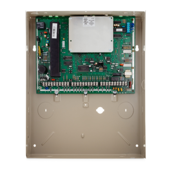
• • • • • • • • • • • • • • • • • • • • • • • • • • • • • • • • • • • • • • • • • • • • • • • • • • VISTA-128BPEN CONTROL Physical: Standard Cabinet (included) 12 1/2"... - Page 118 Vista-128BPEN Installation and Setup Guide...
-
Page 119: Contact Id Event Codes
A P P E N D I X Contact ID Event Codes • • • • • • • • • • • • • • • • • • • • • • • • • • • • • • • • • • • • • • • • • • • • • • • • • • TABLE OF CONTACT ID EVENT CODES Code Definition... - Page 120 Vista-128BPEN Installation and Setup Guide Alpha Event Description Alpha Event Description TAMPER Tamper MISSED ARM Missed Arm FIRE TRB Fire Trouble DIALER RST Dialer Restore (Shutdown) FAIL TO COMM Failure to Communicate SYSTEM RST System Restore (Shutdown) BELL TROUBLE Bell Trouble...
-
Page 121: Index
Index • • • • • • • • • • • • • • • • • • • • • • • • • • • • • • • • • • • • • • • • • • • • • • • • • • Access Group ................. - Page 122 VISTA-128BPEN Installation and Setup Guide Downloading................7-1 Downloading Access Security..........7-1 Downloading Requirements ............. 7-1 Cabinet Lock ................3-1 Dual Reporting................. 5-6 California State Fire Marshal (CSFM)........A-2 Duress Codes Level 6.............. 9-2 Call Waiting Defeat ..............5-10 Duress Reporting..............9-2 Callback ...................
- Page 123 Index Hardwire and Optional Expansion Zones........1-1 No Alarm Response Type 23..........4-7 Hardwired (HW) Type 01............4-7 Non-UL Installations..............3-4 Holiday Schedule ..............6-3 Normally Closed or EOLR (Zones 2-8)........5-5 Holiday Schedule Programming ..........6-7 Number of Partitions .............. 5-12 Holiday schedules ..............
- Page 124 VISTA-128BPEN Installation and Setup Guide Supervised RF..............3-16 Supervised RF (RF) Type 03 ........... 4-7 Supervision Pulses for LRR ........... 5-14 Quick Arm .................5-3, 9-1 Supplementary Power Supply..........3-4 Quick Exit................. 5-1 Suppress Transmitter Supervision Sound ......5-11 Swinger Suppression ............... 5-7 System Commands ..............
- Page 125 Index Using ACS Zone Inputs............4-9 VA8200 ................2-4, 3-21 VA8201 .................. 3-23 View Capabilities..............9-1 VIP Module ................3-28 VIP Module Phone Code ............5-3 Vista Gateway Module ............3-26 VISTA Gateway Module ............4-9 VistaKey................3-25, 4-9 VistaKey Dialer Enables............4-9 Wheelock AS-121575W ............
-
Page 127: The Limitations Of This Alarm System
WARNING! THE LIMITATIONS OF THIS ALARM SYSTEM While this System is an advanced wireless security system, it does not offer guaranteed protection against burglary, fire or other emergency. Any alarm system, whether commercial or residential, is subject to compromise or failure to warn for a vari- ety of reasons. - Page 128 For the latest warranty information, please go to: www.honeywell.com/security/hsc/resources/wa 2 Corporate Center Drive, Suite 100 P.O. Box 9040, Melville, NY 11747 Copyright © 2010 Honeywell International Inc. www.honeywell.com/security Ê800-05855Š 800-05855 2/10 Rev B...