Table of Contents
Advertisement
Quick Links
Advertisement
Table of Contents

Related Manuals for Omron 3G3JX


Summary of Contents for Omron 3G3JX
- Page 1 At the end of this document you will find links to products related to this catalog. You can go directly to our shop by clicking HERE. HERE...
-
Page 2: Quick Start Guide
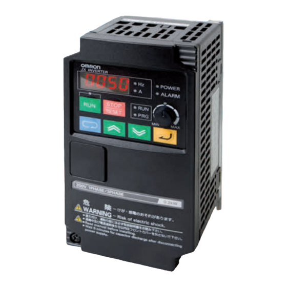
Cat. No. I128E-EN-01 Compact and complete Model: 3G3JX 200 V Class Three-Phase Input 0.2 to 7.5 kW 200 V Class Single-Phase Input 0.2 to 2.2 kW 400 V Class Three-Phase Input 0.4 to 7.5 kW QUICK START GUIDE... - Page 3 OMRON. No patent liability is assumed with respect to the use of the information contained herein. Moreover, because OMRON is con- stantly striving to improve its high-quality products, the information contained in this manual is subject to change without notice.
-
Page 4: Table Of Contents
JX Quick Start Guide 1 SPECIFICATIONS ................. 3 1.1 Upon receipt ......................... 3 1.2 Power ratings........................3 1.3 Technical specifications ....................... 4 2 INSTALLATION..................5 2.1 Wiring sizes and protection ....................5 2.2 Installation dimensions......................5 2.3 Installation environment ..................... 6 2.4 Wiring overview........................ - Page 5 JX Quick Start Guide...
-
Page 6: Upon Receipt
AX-FIJ3005-RE A4007 0.75 A4015 3 x 400 V A4022 AX-FIJ3011-RE A4040 A4055 13.0 AX-FIJ3020-RE A4075 16.0 1.2 Power ratings Single-phase 200 V: 3G3JX- AB002 AB004 AB007 AB015 AB022 Three-phase 200 V: 3G3JX- A2002 A2004 A2007 A2015 A2022 A2037 A2055 A2075... -
Page 7: Technical Specifications
SPECIFICATIONS Three-phase 400 V: 3G3JX- A4004 A4007 A4015 A4022 A4040 A4055 A4075 0.75 Motor (kW) Applicable motor capacity 380 V 10.5 Inverter capacity (KVA) 480 V 10.8 13.3 Output Rated output current (A) 13.0 16.0 characteristics Max. output voltage Proportional to input voltage: 0 to 480 V Max. -
Page 8: Installation
INSTALLATION 2 INSTALLATION 2.1 Wiring sizes and protection Wiring Applicable device Motor output (kW) Inverter model 3G3JX- Earth leakage breaker (ELB) Fuse size (class J) Rated 600 V Power cable (mm A2002 1.25 10 A A2004 10 A 1.25 A4004... - Page 9 INSTALLATION Dimensions in mm Max. applicable Voltage class Inverter model 3G3JX- Figure motor output kW Weight (kg) A4004 130.5 0.75 A4007 A4015 157.5 Three-phase A4022 400 V A4040 A4055 167.5 77.5 A4075 JX Quick Start Guide...
-
Page 10: Installation Environment
5 cm min. 10 cm min. • You can install multiple 3G3JX inverters side by side in the control panel (side-by-side installation). Again, keep the ambient temperature within the specified range (40°C or below). • If the ambient temperature is from 40°C through to 50°C, the carrier frequency should be reduced and the inverter capacity should be increased. -
Page 11: Wiring Overview
INSTALLATION 2.4 Wiring overview 3-phase 200 VAC Inverter 1-phase 200 VAC 3-phase 400 VAC U/T1 R (L1) V/T2 Motor S (L2) T/N (L3) W/T3 For Source logic Note: To connect the DC reactor, 4.7 k Ω remove the short-circuit bar. PD/+1 DC reactor Relay output... -
Page 12: Control Wiring
U/T1 V/T2 W/T3 P/+ PD+1 Main Circuit Terminal Block *1. For 3G3JX-AB, R/L1 corresponds to L1 and T/L3 to N, terminal S/L2 is not available. Connect a single-phase 200 VAC input to terminals L1 and N. 2.6 Control wiring Relay output... -
Page 13: Digital Inputs Sink/Source (Npn/Pnp) Settings
INSTALLATION 250 VAC 2.5 A NC output 30 VDC 3 A Factory default relay settings Under normal operation: AL2-AL0 closed NO output 250 VAC 1 A Digital Under abnormal operation: AL1-AL0 open 30 VDC 1 A output Relay output common 5 V, 100 mA min signals Multi-function output terminal... -
Page 14: Programming Jx
PROGRAMMING JX 3 PROGRAMMING JX 3.1 Digital operator Data display RUN command LED indicator FREQ adjuster Operation keys Item Name Description POWER LED indicator Lit when the power is supplied to the control circuit. ALARM LED indicator Lit when an inverter error occurs. RUN (during RUN) LED indicator Lit when the inverter is running. -
Page 15: Keypad Navigation
PROGRAMMING JX 3.2 Keypad navigation d001 Press the key d083 f001 f004 a001 a--- a001 0000 0001 9999 b--- a002 0000 c--- 0001 9999 a003 h--- *1. Data is not stored by pressing the Mode key. *2. Press the Enter key to store the data. *3. -
Page 16: Parameter Initialization
PROGRAMMING JX 3.3 Parameter initialization • Initialize the parameters using the following procedure. • To initialize the parameters, set parameter b084 to “02”. Key sequence Display example Description Power On Press the Mode key once, and then press the Decrement key three times to b--- display “b---”. -
Page 17: Ramps Adjustment
PROGRAMMING JX • Select Run command source on parameter A002 Parameter Parameter name Details A002 RUN command selection 01: Terminal 02: Digital operator 2nd RUN command selection A202 03: ModBus communication • Adjust the stopping method by b091 and the acceleration/deceleration ramps on parameters F002 and F003 Parameter Parameter name Details... -
Page 18: Dc Injection Braking
PROGRAMMING JX F003 Deceleration time 1 0.01 to 3000. s F203 2nd deceleration time 1 Standard acceleration and deceleration is linear. The inverter CPU can also calculate an S-curve acceleration or deceleration curve as shown. Even if the shape of the ramps change the time keeps being the same one set in F002/F003. Curve settings for acceleration and deceleration are independently selected. - Page 19 PROGRAMMING JX ter A053, during which the motor will free run. If free-run is selected as stopping method the DC injection braking will start just when the Run commands turns OFF. DC Brake at stop F-SET A053 A055 F-OUT A053 •...
-
Page 20: V/F Curve
PROGRAMMING JX Parameter Parameter name Description A053 DC injection braking delay time The delay from the end of controlled deceleration to start of DC braking (motor free runs until DC braking begins) 0.0 to 5.0 s A054 DC injection braking power 0. -
Page 21: Torque Boost Function
PROGRAMMING JX Period c: Provides constant voltage within a range from the base frequency to the maximum frequency. 3.8 Torque boost function This function helps to compensate insufficient motor torque in a low speed range. • Compensates the voltage drop caused by the primary resistance of the motor or wiring increasing the torque in a low speed range. -
Page 22: Digital Inputs
The function codes in the following table let you assign between a wide range of functions to any of the five logic inputs for the 3G3JX inverter. The functions C001 through C005 configure the terminals [1] through [5] respectively. The “value” of these par- ticular parameters is not a scalar value, but it is a discrete number that selects one option from many available options. - Page 23 PROGRAMMING JX Input function summary table Option Terminal Function name Description code symbol Reset The trip condition is reset, the motor output is turned OFF, and powerup reset is asserted Normal power-ON operation Thermistor input The inverter can detect motor temperature and, if the temperature exceeds the specified level, trips to shut off the output (E35).
-
Page 24: Digital Outputs
PROGRAMMING JX 3.10 Digital outputs Function codes in the following table let you assign different options into logical outputs (terminal [11] and [AL]) on parameters C021 and C026. Input function summary table Option Terminal Function name Description code symbol Signal during RUN When the inverter is in Run Mode Constant speed arrival signal When output to motor is at the set frequency... -
Page 25: Analog Output Am Terminal
PROGRAMMING JX The settings are as follows. (VR: FREQ adjuster). If AT is not allocated to any of the multi-function input, this means the AT input = OFF in the above table. A005 set value AT terminal input status Analog input enabled OI-L OI-L OI-L... -
Page 26: Electronic Thermal Function
* To switch to the 2nd control, allocate 08 (SET) to the multi-function input terminal and then turn it on. Electronic thermal level (motor protection level) (Example) 3G3JX-AB007, rated current: 4.0 A, setting range: 0.8 to 4.0 A. Time before trip (s) Example where electronic thermal level is b012 = 5.0 A... -
Page 27: Carrier Frequency
PROGRAMMING JX 3.14 Carrier frequency You can change the PWM waveform carrier frequency output from the inverter. Parameter Parameter name Data Default setting Unit b083 Carrier frequency 2.0 to 12.0 • With the carrier frequency set high, you can reduce metallic noise from the motor. However, this may increase electrical noise or leakage current from the inverter. -
Page 28: Overload Limit/Warning
PROGRAMMING JX • PID feedback (FB) upper/lower limit Data Symbol Function name Status Description PID FB status output Shifts output when exceeding the upper limit or falling below the lower limit Available output terminals 11-CM2, AL2-AL0 (or AL1-AL0) Requires settings C021, C026, C052, C053 •... -
Page 29: Controlled Stop At Power Loss
PROGRAMMING JX Parameter Parameter name Data Default setting Unit b130 Overvoltage LAD stop function 00: Disabled 01: Enabled b131 Overvoltage LAD stop function level 200-V class: 330. to 395. 380/760 setting 400-V class: 660. to 790. b133 Overvoltage protection function 00: Disabled selection during deceleration 01: Enabled... -
Page 30: Parameter List
PARAMETER LIST 4 PARAMETER LIST The PDU (Process Data Unit) register number are addressed starting at zero. Therefore register numbered “0012h” addressed as “0011h”. Register address value (transmitted on Modbus line) is 1 less than the Register number of the table 4.1 Parameter group D: Monitors Changes Modbus... - Page 31 PARAMETER LIST Modbus Changes Parameter Default Function name Monitoring or data range (digital operator) during Unit address setting operation (hex) A021 Multi-step speed reference 1 0.0/starting frequency to max frequency 102B A022 Multi-step speed reference 2 102D A023 Multi-step speed reference 3 102F A024 Multi-step speed reference 4...
-
Page 32: Parameter Group B
PARAMETER LIST Modbus Changes Parameter Default Function name Monitoring or data range (digital operator) during Unit address setting operation (hex) A093 Deceleration time 2 0.01 to 3000. 15.00 1076 (high) 1077 (low) A293 2nd deceleration time 2 151B (high) 151C (low) A094 2-step accel/decel selection 00: Switched via multi-function input 09 (2CH) - Page 33 PARAMETER LIST Modbus Changes Parameter Default Function name Monitoring or data range (digital operator) during Unit address setting operation (hex) b031 Soft lock selection 00: Data other than b031 cannot be changed when ter- – 10BC minal SFT is ON 01: Data other than b031 and the specified frequency parameter cannot be changed when terminal SFT is ON 02: Data other than b031 cannot be changed...
-
Page 34: Parameter Group C
PARAMETER LIST 4.4 Parameter group C Changes Modbus Parameter Default Function name Monitoring or data range (digital operator) during Unit address setting operation (hex) C001 Multi-function input 1 selection 00: FW (forward) – 1103 01: RV (reverse) 02: CF1 (multi-step speed setting binary 1) 03: CF2 (multi-step speed setting binary 2) C201 2nd multi-function input 1 selection... -
Page 35: Parameter Group H
PARAMETER LIST Changes Modbus Parameter Default Function name Monitoring or data range (digital operator) during Unit address setting operation (hex) C074 Communication parity selection 00: No parity – 113B 01: Even 02: Odd C075 Communication stop bit selection 1: 1-bit –... - Page 37 OmRON EUROPE B.V. Wegalaan 67-69, NL-2132 JD, Hoofddorp, The Netherlands. Tel: +31 (0) 23 568 13 00 Fax: +31 (0) 23 568 13 88 industrial.omron.eu Austria France Netherlands Spain Tel: +43 (0) 2236 377 800 Tel: +33 (0) 1 56 63 70 00...
-
Page 38: Product Code
Below is a list of articles with direct links to our shop Electric Automation Network where you can see: • Quote per purchase volume in real time. • Online documentation and datasheets of all products. • Estimated delivery time enquiry in real time. •...