Chamberlain Elite EL25 Programming Manual
Hide thumbs
Also See for Elite EL25:
- Installation manual (30 pages) ,
- Quick start manual (26 pages) ,
- Instruction manual (4 pages)

Related Manuals for Chamberlain Elite EL25


Summary of Contents for Chamberlain Elite EL25
- Page 1 ® ™ EL25 EL25 Keypad Programming Manual Keypad Programming Manual Telephone entry/access control system with a 25 directory code capacity © 2005 The Chamberlain Group, Inc. All Rights Reserved...
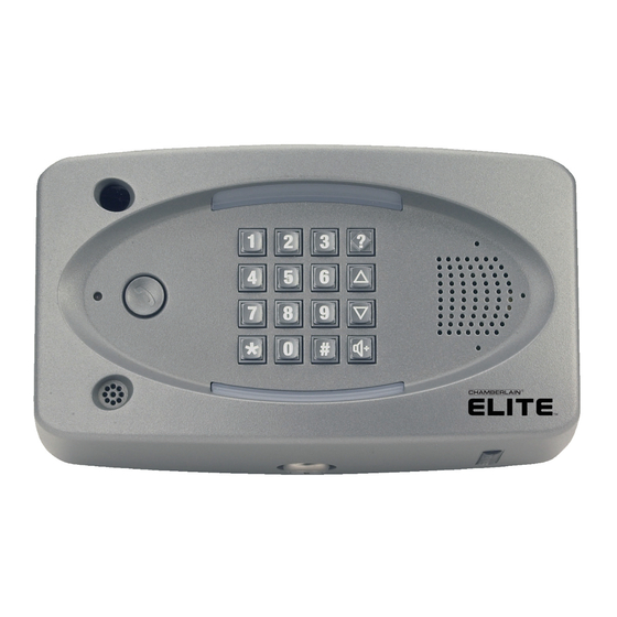
- Page 2 Microphone Status LED: Solid Red: EL25 idle power, doors are locked. Lock Blinking Red: Strikes and Out for a door. Solid Green: Granted access for a door. Blinking Green: Latch for a door is unlocked.
-
Page 3: Table Of Contents
Enter Programming Mode Exit Programming Mode System Feedback / Responses (Beeps) Sending Direct Commands from Resident's Phone 2 111 Programming Multiple Units Overview EL25 Setup “Your Settings” Getting Started Setup External Access Control Devices 60 61 65 66 19-21 Your Door Settings... - Page 4 Table of Contents Programming Numbers Page Access Cards Con't 73 74 Facility Codes Card Types Transmitters (Remotes) About Transmitters (Remotes) 91 94 95 Add, Edit, or Delete Transmitter Codes 41-43 Activate or Deactivate a Transmitter Verify a Transmitter Time Zones, Holidays and Clock About Time Zones Creating Time Zones Setting Holidays...
-
Page 5: All
Guide for Programming the EL25 Programming Factory Page Description of Task Programming Procedure Number Setting Entering Programming Mode (6 Digit Password) Exiting Programming Mode Change or Verify the Unit's Password 000000 1 # (1 to change; 2 to verify) # (six-digit code) # Set Unit ID Number and No. - Page 6 # (End Date = yymmdd) # (End Time = hhmm) # Optional Steps Indicated with a Background, all other steps are Required To enter programming mode from the EL25: Press and the 6-Digit Password (2 short beeps will be heard)
- Page 7 Programming Factory Page Description of Task Programming Procedure Number Setting Delete an Entry Code 57 # (entry code) # 60 # (device 1-4) # (device type 0-2; 0 = no device, No Device Assign Each External Access Control 1 = wiegand card reader or keypad, 2 = RF receiver) # Device a “Door Number”...
- Page 8 Programming Factory Page Description of Task Programming Procedure Number Setting 85 # (lost or stolen card PIN code) # (facility code) # Replace a Card (card type, 26 or 30) # (new card PIN) # (new facility code) # (new card type, 26 or 30) # 86 # (card PIN code) # (facility code) # (card type, 26 Verify a Card or 30)
- Page 9 206 # 101010 # Optional Steps Indicated with a Background, all other steps are Required To enter programming mode from the EL25: Press and the 6-Digit Password (2 short beeps will be heard) Exiting programming mode allows changes to take effect The Pound Key (#) must be used as Data Field Separator and to Save Data at the end of the sequence.
-
Page 10: El25 Introduction
The sample installations on the next few pages will help familiarize you with the features of your EL25. You MUST know how your system is laid out to program it with this manual. If you have questions about your configuration, please contact your installing dealer for more information. - Page 11 Manager Board Modes of Access Visitors or residents of a building or complex controlled by an EL25 unit can gain access using one of the following methods: Resident Phone (Directory Codes): A visitor may dial a resident's directory code from the unit to contact him/her.
- Page 12 Example Single Family Residence (NPB) This EL25 can operate the vehicular gate with an access code or by remote control. It will allow Pedestrians entry with an Access Card. It will also open the gate automatically for exiting cars. Car Exit Sensor...
-
Page 13: Multi-Resident Complex (Dial-Out Or Manager Sharing)
Example Multi-Resident Complex This EL25 can control the property with a vehicular gate operator, access card or the unit's keypad. Residents can use programmed transmitters for the parking lot, access cards for the pool or a personal entry code for the main entrance. The main entrance is equipped with a door sensor to alert management about inappropriate use. - Page 14 Your System Layout How your system has been wired is an important part of programming it. Write down your configuration. To help visualize it, draw a map of it below. If you're unsure of your setup, consult your dealer/installer for more information. External Access Control Device(s) connected to aux board(s) Door Sensor Door Stat 1...
-
Page 15: Programming Single Unit Overview
Local/Remote DTMF Phone: You may use the keypad on a local or remote phone to program the system. The unit responds to the DTMF signals generated by your touch-tone phone. (Next Page) Direct/Modem Connection to a PC: In order to program the EL25 with a direct or modem connection, your PC must be ®... -
Page 16: Enter Programming Mode
Note: If the EL25 and an answering machine (or answering service) utilize the same phone line, let the line ring at least (2) two times, hang-up, and call back within one (1) minute. The EL25 will answer on the second call. If the unit does not answer, you may need to change the ring count (see page 54). -
Page 17: System Feedback / Responses (Beeps)
1 Lift the receiver and press 1A If multiple EL25 units are sharing the same phone line, then a Unit ID Code (1-7) will need to be entered at this time. (See page 17 for more information about Multiple Unit Sites). -
Page 18: Programming Multiple Units Overview 2 111
Programming Multiple Units Overview Up to seven (7) EL25s can be installed on a single telephone line. Each unit must have a “ Unique Unit ID” number and the “Number of Units in Chain” assigned to it. Set the Unit ID Number and Number of Units in Chain: The unit ID identifies each unit within a chain. -
Page 19: El25 Setup "Your Settings
EL25 SetUp “Your Settings” The EL25 comes preprogrammed with Factory Settings. When the unit is first installed, you need to program each feature. Review the unit's factory settings before programming (see Quick Reference Guide , pages 4-8 for the Factory Settings). -
Page 20: Setup External Access Control Devices 60 61 65
Setup External Access Control Devices The EL25 must have all external access control device options configured into it, before many of the other programming options can proceed. You must tell the unit “ what it's wired to ” and “... - Page 21 DO NOT PROCEED. Consult your Installer and/or refer to the installation manual for assistance. The EL25 can be equipped with Wiegand reader and radio frequency (RF) modules that allow your system to accommodate external access control devices such as a Wiegand-compatible card reader (keypad) and RF receiver.
- Page 22 Assign “Each” Door Number to One or More Relays: When a valid access code is used at an external access control device (Door), the EL25 can be set to activate Factory Settings: Door 1 Activates Relay 1; Door 2 Activates Relay 2;...
-
Page 23: "Your" Door Settings
Relay Relay Mode Relay Function Time (Seconds) When “Your Door Settings” or “ Door 1,2,3 or 4 ” are referenced throughout this manual, this completed chart will outline how your EL25 system will function. Sample: EL25 Controlling 1 Door (Next Page for Illustration) - Page 24 Activates Camera 10 sec. REX Device (Exit) EL25 Main Keypad (Front Door) EL25 Controlling 2 Doors and Vehicle Gate Card Reader (Back Door) Relay 3 - Strike Mode Unlocks Door for 10 sec. Relay 2 - Control Mode Turns on Security Light for 60 sec.
- Page 25 EL25 Controlling 4 Doors Card Reader (Back Door) Relay 3 - Strike Mode Unlocks Door for 10 sec. Card Reader (Manager's Door) Relay 4 - Strike Mode Unlocks Door for 10 sec. Relay 2 - Strike Mode Unlocks Door for 10 sec.
-
Page 26: Directory Codes
Do you know the resident's phone number? The system needs the phone number so it can dial the resident when prompted. If the resident's phone has an extension, the EL25 will need that data as well. Will the resident want a Do Not Disturb schedule? If the resident doesn't want to be disturbed during •... -
Page 27: Set A Directory Code Length 6
Set Directory Code Length Factory Setting: 2 1 Press Then 2 Enter New Directory Code Length (1or 2). Then ( Example: Makes Directory Code length 2 digit Maximum. Important: You will not be able to decrease the Directory Code length if codes already exist that are more than the attempted decrease length. - Page 28 Add or Edit Full Function Directory Code: When adding a full function Directory Code, it will default as “active”. To deactivate a code, or to activate or deactivate on a specific time and date, see Activate or Deactivate Directory Code on page 29. 1 Press Then Enter Call Forward Schedule (0-63).
-
Page 29: Enable Or Disable Do Not Disturb Schedule
Delete ALL Directory Codes: This will delete Directory Codes from unit. Important: Once you delete the Directory Codes, you cannot retrieve them unless they are saved in Versa XS. 1 Press Then Then 2 Enter Enable or Disable Do Not Disturb Schedule Do Not Disturb (DnD) Schedules prevent visitors from calling residents during specified time frames. -
Page 30: Add/Modify Resident Dnd And/Or Call Forwarding
Add / Modify Resident DnD and/or Call Forwarding Add/Modify DnD and Call Forwarding Information for the Resident (NPBI) or manager. Do Not Disturb (DnD) Schedules prevent visitors from calling the Resident (NPBI) or manager phone during specified time frames. Call Forwarding redirects visitor calls to an outside telephone number instead of ringing the Resident (NPBI) or manager phone. -
Page 31: Verify A Directory Code 47
Verify Directory Code Verifies that a Directory Code exists in the unit's database. 1 long Beep: Indicate the code Does Not exist in the database. Double Beep: Indicate the code Does exist in the database. Then 1 Press 2 Enter Directory Code (1-2 digits). Then ( Example: Then System Beeps ONCE Directory Code “12”... -
Page 32: Entry Codes
On the unit's keypad, enter the assigned “Entry Code”. If you make a mistake entering the code, press Resident keys in personal Entry Code EL25 grants entry Before adding or modifying Entry Codes, answer the following questions: • Have you chosen the Entry Code number you will assign? This number will be assigned to a resident. The resident will enter this number on the unit keypad to prompt the system to grant access. -
Page 33: Set An Entry Code Length
Set an Entry Code Length Factory Setting: 4 Digits 1 Press Then 2 Enter New Entry Code length (3-9 digits). Then ( Example: Makes Entry code length 5 digit maximum. Important: You will not be able to decrease the Entry Code length if codes already exist that are more than the attempted decrease length. - Page 34 Add or Edit Full Function Entry Code: When adding a full function Entry Code, it will default to “Active” at the current date and time with no deactivation date. To deactivate a code, or to activate or deactivate on a specific time and date, see Activate or Deactivate Entry Code on page 34.
-
Page 35: Activate Or Deactivate An Entry Code
Activate or Deactivate an Entry Code This allows you to activate or deactivate an Entry Code, also on a specific date and time. Activate / Deactivate an Entry Code: Disabling the Activate Entry Code 3 , the Entry Code will always be deactivated. If you enable the Activate Entry Code 3 , then the four statements could apply: you disable the Start Activation Date 4 and disable the End Deactivation Date 5 and omit all dates and times,... -
Page 36: Access Cards
Entry cards allow entry or exit through a gate/door. This feature allows residents to swipe a card into a card reader (other card types and card readers may apply) to prompt the system to grant access. Resident uses Card Reader EL25 grants entry Before adding or modifying cards, answer the following questions: •... -
Page 37: Add, Edit, Or Delete Cards 80 81
Notes: A basic card will be active with the current system time and never deactivate, unlock all doors connected to the EL25, with no time constraint (i.e., can be used 24 hours a day, 7 days a week). For new records, if you don't add a Facility Code or Card Type, the system will add the defined default values. - Page 38 Add a Group of Cards at Once: This feature allows you to enter a large number of cards into the system at one time. Individual cards from a group can be edited later. For example, you have 250 cards that you want to enter into the system so that every time someone needs a card, you won't have to program the system to individually enter a new card.
-
Page 39: Activate Or Deactivate A Card
Delete a Card: Facility Code (0 to 63 or 0-255, depending on 1 Press Then card type). Then ( 2 Enter Card Number to be deleted (1-65534). Then ( Card Type (26 or 30). Then ( Example: Deletes 26-bit card number “12670” and Facility Code “1”. Required Step Optional Step, Press ( ) to Skip. -
Page 40: Verify A Card
30-bit cards have a Facility Code range of 0-63. 26-bit cards have a Facility Code range of 0-255. Card Types The EL25 accepts two card types: Standard 26-bit cards and Sentex 30-bit cards. Set the Default Card Type: Use this to set a default card type (standard 26-bit or Sentex 30-bit). If you set a default card type, every time Factory Setting: Sentex 30-bit. -
Page 41: Transmitters (Remotes)
A resident may use a Passport radio frequency transmitter (remote) to enter a controlled area. When pressed, the transmitter sends a signal to the EL25. It reads this data and determines the validity of the code. If the code is valid, the EL25 will activate the device(s) connected to it, for example, opening a parking lot gate or other controlled vehicle entryways. -
Page 42: Add, Edit, Or Delete Transmitter Codes 90 91 94
Add, Edit or Delete Transmitter Codes When adding or editing transmitter codes, note the following: back The label on the of the transmitter displays the codes necessary to program the transmitter. • Sequence Code ID Number Facility Code Button Number PASSPORT Transmitter Number SW ID SEQ FC... - Page 43 Add or Edit a Full Function Transmitter: Add or edit a full function transmitter. When adding a Full Function transmitter, it will default as “ active ”. To deactivate a transmitter, or to activate or deactivate on a specific time and date, see Activate or Deactivate Transmitter (Page 44).
- Page 44 Replace a Lost Transmitter: 1 Press Then 2 Enter Lost Transmitter Number (1-65534). Then ( 7 Enter New Transmitter Number (1-65534). Then ( 3 Enter Facility Code (0-255). Then ( 8 Enter New Facility Code (0-255). Then ( 4 Enter Sequence Code (0-2). Then ( 9 Enter New Sequence Code (0-2).
-
Page 45: Activate Or Deactivate A Transmitter
Activate or Deactivate a Transmitter Activate or deactivate a transmitter on a specific date and time. Activate / Deactivate a Transmitter: Disabling the Activate Transmitter 7 , the Card will always be deactivated. If you enable the Activate Transmitter 7 , then the four statements could apply: you disable the Start Activation Date 8 and disable the End Deactivation Date 9 and omit all dates and times, the Transmitter will immediately become active and stay that way until the code is deactivated or deleted. -
Page 46: Time Zones, Holidays And Clock
Time Zones, Holidays and Clock About Time Zones (Schedules) Time Zones (Schedules) allow you to create time periods to grant or deny access to a building or complex. Time Zones may be assigned to Access Codes (e.g., Entry Codes, Cards, etc.) or doors and utilize military time. -
Page 47: Creating Time Zones
Saturday, Sunday, and holidays). Setting Holidays Program the EL25 with up to 16 holiday dates that replace existing time zone (e.g., auto-lock/unlock and card/code entry schedules) during the defined date. For example, if New Year's Day is set up as a holiday, you may set up the system so that employees who ordinarily have access with entry cards and codes will not be granted entry on January 1st. -
Page 48: Assigning Door Use And Unlock Time Zones 11
Assigning Door Use and Unlock Time Zone Unlock Time Zones allow you to automatically unlock and lock doors/gates at times you specify. Assign “Door Use Time Zone”: Door Use Time Zone allows you to set up time periods and days during which access is restricted for all entry codes, cards, and transmitters. -
Page 49: Deleting All Time Zones 205
Deleting ALL Time Zones This will delete time zones from unit. Important: Once you delete the time zones, you cannot retrieve them unless they're saved in Versa XS. 1 Press Then 2 Enter Then Setting the Clock An accurate clock is critical to the proper use of schedules, time zones and for accurately reporting transactions. -
Page 50: Security Features
Security Features Setting Anti-Passback The Anti-Passback feature deters someone from “passing back” his/her access code/card to unauthorized individuals so they can gain entry into a restricted area. There are types of anti-passback features: • True Anti-Passback requires residents to exit before entering again (and vice versa). For example, if you have a door with Card Reader 1 (to enter) and Card Reader 2 (to exit), a resident entering with Card Reader 1 will have to swipe his/her card in Card Reader 2 to exit before swiping on Card Reader 1 again (and vice versa). -
Page 51: Configuring The Alarm Features
Set Anti-Passback Time: With “timed” anti-passback, after a resident uses a card/code/transmitter on a specific entry device, they Factory Setting: 3 Minutes cannot use the device again until a specified amount of time elapses. 1 Press Then 2 Enter Number of Minutes (1-60). Then ( Example: Sets the Anti-Passback time to 5 minutes. - Page 52 Configure “Door Forced Open” Alarm Feature: When enabled, doors that are forced open will trigger an alarm. The alarm will activate the relays you specify. The relays can remain active until the relay time expires or until the alarm condition clears. Factory Setting: Disabled 1 Press Then...
-
Page 53: Changing Or Verifying The Unit Password
Changing or Verifying the Unit Password The EL25 unit will not allow you to program the system unless you know the unit's password. If you lose the unit's When changing the unit's password, save a copy of it in a secure location. -
Page 54: Communications To And From Unit
, and disconnects from the telephone line to wait for commands. Some telephone companies offer special features that require you to press a preceeding WWor mm. If you subscribe to such services and the EL25 interferes with them, you can program the unit to accept Factory Setting: 00 different prefixes. - Page 55 Dial “0-9” First to Get an Outside Line Using an Automated Phone System: When a EL25 is connected to a PBX telephone system (Automated), it can be programmed to dial a specific PBX number (0-9) then pause briefly, allowing the PBX system to give the unit an outside line.
-
Page 56: Speaker-Microphone Settings 18
Set a Phone Number's Extension Delay Time: When the EL25 is programmed to dial a resident with a phone number and extension , and the extension needs to be entered a short time after the automated phone system's greeting message has finished, the unit allows a delay time, between the phone number and the extension number or call forward extension number. -
Page 57: Visitor Communication Settings 5 14
Enables the voice mail. Change the Visitor Call Response Keys: When a visitor contacts a resident with the EL25, the resident can allow entry by pressing one of the keys on their phone. Options are: Activate all Entry Devices on Door 1 Relay(s) - Page 58 Example: 2 Enter Maximum Ring Count Allowed (1-9). Then ( Sets the maximum number of rings to “7”. To enter programming mode from the EL25: Press and the 6-Digit Password (2 short beeps will be heard) Exiting programming mode allows changes to take effect If you make an error during an entry, press the asterisk key ( ) to begin again.
-
Page 59: Postal Lock/Autocall/Exit/Door Sensor Devices
Deact Deact When a loop detector type device is triggered, only Relay “3” will activate. To enter programming mode from the EL25: Press and the 6-Digit Password (2 short beeps will be heard) Exiting programming mode allows changes to take effect The Pound Key (#) must be used as Data Field Separator and to Save Data at the end of the sequence. -
Page 60: Request To Exit Device (Rex)
Request to Exit Device (REX) When activated, a Request to Exit Device (REX) opens a door or activates specific relays you can assign. It is typically used for residents to exit through a controlled door or gate. • The REX can be assigned a door number (1-4) that will activate preset relay(s) from Your Door Settings .(See Page 22) -
Page 61: Door Sensing Devices
Door Sensing Devices The Door Sensing Device determines if a door is held open too long or forced open. When these conditions occur, the system can activate an alarm, camera or other relay controlled device (see Configure the Alarm Features on pages 50 and 51 for more information). •... -
Page 62: Direct Commands From The Phone
Enable (1) or Disable (0). Then ( Talk through the EL25 Speaker: Initiate communications from a telephone through the EL25 at any time to greet visitors, ward off vandals, etc. 1 Press (from the residence phone). If you are in the programming mode, go to next step. -
Page 63: Real-Time Monitoring
122 or 123 - Enter the Latch Time (hhmm=Hour and Minute). Then ( Optional, Press ( ) to Skip. Example A: Relay(s) will activate now from EL25 Activates Relay(s) assigned to “Door 2” in Your Door Settings when the final pound key ( ) is pressed. -
Page 64: Reset/Restore The Unit And Database
Reset/Restore the Unit and Database If you make an error during an entry, press the asterisk key ( ) to begin again. Restore Factory Settings: Proceed With CAUTION! When this is completed, Directory Codes, Entry Codes, Cards, Transmitters, Holidays and Schedules WILL be reset. -
Page 65: Glossary
Alarms - The EL25 unit may be configured to trigger an alarm (e.g., Activate a siren and/or a warning light, etc.) when an alarm condition occurs. These conditions include a door held open too long, a door forced open, or keypad errors that exceed the maximum allowed. - Page 66 - Identification number for each unit in a multiple unit setup sharing the same phone line. Versa XS - The software to program the EL25 with. Visitor - A visitor can communicate with residents via the EL25. A resident can grant or deny a visitor access with their touch tone phone. Page 65...
-
Page 67: Appendix
Appendix Appendix Access Cards Directory Codes – About Cards – About – Activating/Deactivating – Activating/Deactivating – Adding Card – Adding – Adding Group of Cards – Changing 27-28 – Deleting Cards – Deleting – Facility Codes – Length of – Type of Cards –... - Page 68 – Rings, Number of – Verifying – Telco Mode – Visitor Response Keys Volume – Visitor Talk Time – Speaker/Microphone – Voice Mail First Setup for Your EL25 – Clock & 20-24 – Doors – Password & 19-21 – Relays –...
- Page 69 ® ™ 845 Larch Avenue Elmhurst, Illinois 60125-1196 © 2005 The Chamberlain Group, Inc. All Rights Reserved 114A2954B...