
Related Manuals for Chamberlain Elite EL25N


Summary of Contents for Chamberlain Elite EL25N
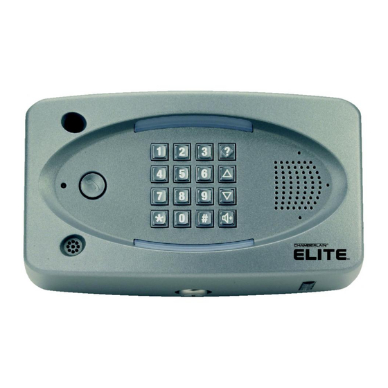
- Page 1 ® ® ™ ™ Installation Manual for Installation Manual for EL MODELS EL MODELS Telephone entry/access control system For more information visit www.devancocanada.com © 2008 The Chamberlain Group, Inc. All Rights Reserved...
-
Page 2: Table Of Contents
Table of Contents Mounting the Unit Page Dimensions EL25 Installation Rotating the Keypad for Vertical Mounting Unlocking/Locking EL2000 EL2000 Installation Wire Type Wire Connections to Unit (Factory Settings for Relays) Wire Specs and Run Distances Power Wire Specs and Run Distances Grounding the Unit Grounding the Unit Phone Lines... - Page 3 Dimensions EL25 Units 6 in. 3-15/16 in. 3/4 in. Conduit Hole Mounting Holes (4) for 5/16 in. Caution! A Static Discharge can Damage Circuit Boards EL2000 Units Knockouts for 3/8 in. Knockouts for 5/16 in. 9 in. AUG 10, 2005 WELCOME 7 in.
-
Page 4: El25 Installation
EL25 Installation Caution! A Static Discharge can Damage Circuit Boards NOTE: This unit is for surface mount applications only. Unplug the 2 Main Harnesses Unlock Unit Carefully Lift Cover Up then Slide Out on Hinges Remove Back Mounting Plate from Cover Line up Notch with Screw and Push Hinge Out... - Page 5 Unlocking EL2000 1. Apply pressure to the right-side of the unit. 2. While maintaining pressure, turn key clockwise 3. Open cover Locking EL2000 1. Turn key counter clockwise to lock position 2. Close cover 3. Apply pressure to left-side until you hear a “click”...
-
Page 6: El2000 Installation
EL2000 Installation NOTE: This unit is for surface and recessed mount ONLY. Unlock Unit Open Cover Slide Front Cover Out of Unplug the 2 Main Harnesses (Optional) Hinges (Optional) Knock-out Desired Mounting Plugs Using Punch Mount Back Housing to Wall or Pedestal Page 5... - Page 7 Wire Connections to the Unit EXIT REQ 4 LED 4 DOOR RELAY 4 STAT 4 EXIT REQ 3 POSTAL LED 3 DOOR STAT 3 RELAY 3 EXIT REQ 2 AUTO TELCO DOOR STAT 4 EXIT LED 2 POWER REQ 1 12VAC/DC RELAY 2 IO Input Board...
-
Page 8: Wire Specs And Run Distances
Wire Specs and Run Distances Use this chart to pull wires in preparation of your installation: Description of Wire Run Maximum Distance Page Wire Specification Grounding the Chassis 12 AWG Copper 12 feet 2 Twisted Pairs 9-14 Residence and Telco Phone Lines 5000 feet* 18-24 AWG Shielded 2-Conductor... - Page 9 Grounding the Units Ensure that the system is grounded properly. The units contain a number of static sensitive components that can be damaged by static discharge. IMPORTANT: An Earth Ground Rod is Strongly Recommended and should be no further than 12 feet from the unit and use a minimum of 12 gauge wire in most cases.
-
Page 10: Wiring 1 Unit To Telco Line
Wiring 1 Unit to Telco Line The bypass board allows the unit to be disconnected without interrupting normal telephone operation. NOTE: Installation where fiber optic phone lines are present may require additional modifications from your telephone provider. Contact your provider for more information. •... -
Page 11: Wiring Multiple Units To Telco Line
Wiring Multiple Units to Telco Line Up to 7 units can share the same phone line. The bypass boards allow the units to be disconnected without interrupting normal telephone operation. NOTE: Installation where fiber optic phone lines are present may require additional modifications from your telephone provider. -
Page 12: Wiring With No Telco Line
Wiring with No Telco Line The unit can be a stand alone system that allows communication between the unit and a resident’s phones. Single Unit NOTE: Ringer Equivalence Number (REN) of “5” maximum. Output Board (See page 6) Use 18-24 AWG 2 twisted pair Ring TELCO... -
Page 13: Wiring To Dedicated Telco Line
Wiring to Dedicated Telco Line NOTE: Installation where fiber optic phone lines are present may require additional modifications from your telephone provider. Contact your provider for more information. Single Unit Telco Entrance Box Demarcation Point LED 4 Use 18-24 AWG RELAY 4 Ring 2 twisted pair... -
Page 14: Wiring To An Internal Phone System
Wiring to an Internal Phone System The units can be wired to any Analog Trunk in an internal home phone system. NOTE: Installation where fiber optic phone lines are present may require additional modifications from your telephone provider. Contact your provider for more information. Single Unit Analog Trunk... -
Page 15: Connection To An Npbi System
Connection To An NPBI System Single Unit Sentex Ovation Unit LED 4 Use 18-24 AWG RELAY 4 2 twisted pair LED 3 RELAY 3 Ring TELCO LED 2 RELAY 2 Never run Telco wires and High Voltage wires in the same conduit. -
Page 16: Wiring A Door Strike Lock
Wiring a Door Strike Lock Output Board (See page 6) DO NOT overload the removable terminal block connectors. One LED 4 wire per hole. RELAY 4 LED 3 RELAY 3 Normally Open TELCO For AC Power: Install a Siemens S10K30 MOV LED 2 For DC Power: Install a (Metal Oxide Varistor) or... -
Page 17: Wiring A Gate Operator
Wiring a Gate Operator Output Board (See page 6) LED 4 RELAY 4 DO NOT overload the removable terminal block connectors. One wire per hole. LED 3 RELAY 3 TELCO LED 2 Normally Open RELAY 2 Common Use 18-24 AWG LED 1 RELAY 1 NOTE: The gate operator can be... -
Page 18: Wiring A Door Sensing Device
Wiring a Door Sensing Device The units can monitor the position of up to four doors/gates and may react to a change in their status with one of the relays (not set as a control relay). For example, if a door is pried open or is held open after its relay deactivates, the unit will record the breach in its transactions and can perform the following actions: •... -
Page 19: Wiring A Radio Frequency Module
Wiring a Radio Frequency Module An optional radio frequency module and a remote antenna can be installed if the residents will access a controlled area with a transmitter. Refer to instructions supplied with the optional RF Module for more information. NOTE: The remote can control 1-4 doors. -
Page 20: Wiring A Postal Lock Switch
Wiring a Postal Lock Switch - EL25 Models Only The Post Office requires installation of a postal lock if postal carriers do not have access to a controlled area. Contact the local post office and arrange for them to install the postal lock while you are on site. The postal lock requires a switch to activate one of the four relays (Configurable with programming number , in the Keypad Programming Manual). -
Page 21: Wiring Power To The Unit
Wiring Power to the Unit The 110 VAC outlet must be dedicated to the unit ONLY. This outlet should be wired back to its own 10 Amp minimum circuit breaker. This will prevent two problems: • Other equipment cannot introduce spikes, noise, surges or dips into the power circuit. •... -
Page 22: Powering Up And Checking The Leds
Powering Up and Checking the LEDs D300 J403 J500 J406 LCD J405 J401 100A J400 DEVICE 3,4 DEVICE 1,2 J402 LEDJ200 SPKR BT300 OV UV Board Used on Model Type Name Description Label EL25 EL2000 D300 PWR LED Indicates Unit is receiving power Connector J405 20-Pin Connector... -
Page 23: Troubleshooting
Troubleshooting Wiring • Check for correct length and AWG of wires. See page 7. • Check that wires are correctly inserted into the terminal blocks (not loose, no two sharing the same position). • Check board markings for correct terminal block placements. •... - Page 24 Repair Parts Installation and Service Information is Available EL25 Parts Call our Toll Free Number 1-800-528-2806 www.chamberlain.com When ordering repair parts, please supply the following information: Description and Model Number Part Description Model Number Part Description Model Number Silver Cover...
-
Page 25: Repair Parts
Repair Parts EL2000 Parts When ordering repair parts, please supply the following information: Description and Model Number Part Description Model Number Part Description Model Number Assembly Display and Display Board 41B989 Interconnect Board 41B997 Assembly, Lock and Key EL2000 41B999 Display Cables Kit 41B990 Assembly, PCB Output Board... - Page 26 Your System Diagram Page 25...
- Page 27 Your Wiring Configuration External Access Control Device(s) connected to optional board(s) (Default Internal Keypad) Device 0 ________________________________________________________________________________ J400 Position on Main Board RF Module Wiegand Device 1 ________________________________________________________________________________ Wiegand Device 2 ________________________________________________________________________________ J407 Position on Main Board RF Module Wiegand Device 3 ________________________________________________________________________________ Wiegand Device 4 ________________________________________________________________________________...
- Page 28 Accessories EL25 Camera Kits EL25BWCAMKT (Black & White Camera) Directory Insert EL25DVRCAMKT (Low Lux DVR Color Camera) ELDI EL25CAMKT (Color Camera) Wiegand Module Kit WOMODKT EL2000 Camera Kits EL2000BWCAMKT (Black & White Camera) EL2000DVRCAMKT (Low Lux DVR Color Camera) EL2000CAMKT (Color Camera) Heater Kit RF Module Kit ELHTRKT...
- Page 29 FCC and DOC Requirements FCC Requirements The units comply with Part 68 of the FCC Rules. The label affixed to this equipment contains, among other information, the FCC Registration Number and Ringer Equivalence Number (REN) for this equipment. You must, upon request, provide this information to your telephone company.
- Page 30 HOW TO ORDER REPAIR PARTS DEVANCO CANADA 19192 HAY ROAD, UNIT Q SUMMERSTOWN, ON K0C 2E0 TOLL FREE: 855-931-3334 www.devancocanada.com WHEN ORDERING REPAIR PARTS PLEASE SUPPLY THE FOLLOWING INFORMATION: 3 PART NUMBER 3 DESCRIPTION 3 MODEL NUMBER...