Sony HKCU1001 Installation Manual
Hd camera control unit
Hide thumbs
Also See for HKCU1001:
- Quick manual (52 pages) ,
- Maintenance manual (393 pages) ,
- Installation manual (102 pages)
Table of Contents
Advertisement
Quick Links
Advertisement
Table of Contents

Related Manuals for Sony HKCU1001


Summary of Contents for Sony HKCU1001
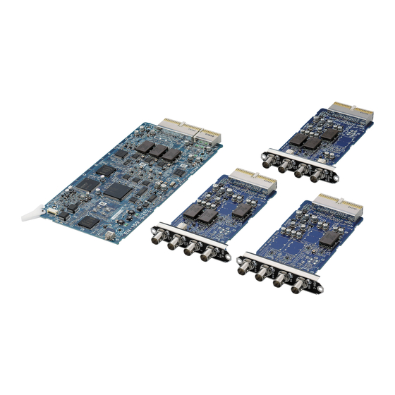
- Page 1 HD CAMERA CONTROL UNIT HDCU3300 SD ENCODER UNIT HKCU1001 MULTI INTERFACE UNIT HKCU1003 SDI OUTPUT EXPANSION UNIT HKCU1005 INSTALLATION MANUAL 1st Edition Serial No. 10001 and Higher : HDCU3300 (UC) Serial No. 30001 and Higher : HDCU3300 (J) Serial No. 40001 and Higher : HDCU3300 (CE)
- Page 2 ! WARNING This manual is intended for qualified service personnel only. To reduce the risk of electric shock, fire or injury, do not perform any servicing other than that contained in the operating instructions unless you are qualified to do so. Refer all servicing to qualified service personnel.
-
Page 3: Table Of Contents
Setting Aspect Ratio Conversion during Down-convert ..........2-13 (E) Trademarks ................3 (E) 2-5-4. Adjusting the Level of the VBS Signal (only when HKCU1001/1003 is installed) ... 2-15 (E) 2-5-5. Adjusting the Level of Signals for 1. Installation Overview Waveform Monitor ........2-15 (E) 2-5-6. -
Page 5: Manual Structure
(service overview and the circuit overview, the main part replacements, electrical alignment, parts list, semiconductor pin assignments, block diagrams, schematic diagrams, board layouts.) required for parts-level service. For obtaining, contact your local Sony Sales Office/Service Center. Part number : 9-968-308-0X . “Semiconductor Pin Assignments” CD-ROM (Available on request) This “Semiconductor Pin Assignments”... -
Page 7: Installation Overview
If the version is lower than the following one, the ROM needs to be replaced and the software needs to be upgraded. In this case, contact your local Sony Sales Office/Service Center. Peripheral equipment Board Ref. -
Page 8: Connectors And Cables
..AES/EBU : BNC AES/EBU format SS-B OUTPUT (1-2) : BNC HD-SDI : SMPTE 292M 0.8 V p-p HKCU1001/1003 75 Z, 1.485 Gbps/1.4835 Gbps VBS (1-2) OUT : BNC SS-C OUTPUT (1-2) : BNC 1.0 V p-p, 75 Z HD-SDI : SMPTE 292M 0.8 V p-p... - Page 9 Y/G OUT : BNC (Not used) WF REMOTE (D-sub 15P, Female) Y : 1.0 V p-p (Video : 0.714 V, synchronous 0.286 V, NTSC), 75 Z 1.0 V p-p (Video : 0.7 V, synchronous 0.3 V, PAL), 75 Z G : 0.7 V p-p, 75 Z _ _ _ _ _ EXT VIEW _ _ _ _ _ B-Y/B OUT : BNC (Not used) B-Y : 0.7 V p-p, 75 Z (NTSC, SETUP : ON, when...
- Page 10 I/O PORT (D-sub 15P, Female) MIC1/MIC2 (XLR 3P, Male) _ _ _ _ _ EXT VIEW _ _ _ _ _ _ _ _ _ _ EXT VIEW _ _ _ _ _ Signal Specifications (0 dBu = 0.775 Vrms) GND/+5 V, OPEN (47 kZ +5 V PULL UP) Signal Specifications...
- Page 11 MIC REMOTE (D-sub 15P, Female) _ _ _ _ _ EXT VIEW _ _ _ _ _ *1 : CHU MIC 1/2 AMP GAIN CONT0 CONT1 CONT2 CHU MIC AMP GAIN Signal Specifications +5.5 V OUT Max. 250 mA 60 dB TALLY GND GND for TALLY 50 dB...
-
Page 12: Cable Wiring Diagram
INTERCOM/TALLY/PGM (D-sub 25P, Female) INTERCOM (5P, Female) _ _ _ _ _ EXT VIEW _ _ _ _ _ _ _ _ _ _ EXT VIEW _ _ _ _ _ (0 dBu = 0.775 Vrms) (0 dBu = 0.775 Vrms) Signal Specifications Signal... -
Page 13: Connection Connectors
(D-sub 25P, Female) JAE DA-25PF-N equivalent . LEMO® WF MODE 1-560-155-00 PLUG, 4P Male FUW. 3K. 93C. TLMC96 *1 (4P, Female) (supplied with HKCU1001/1003) HDCU3300 1-564-742-11 PLUG, BNC or RCP/CNU 1-766-848-11 PLUG, 8P Male VBS (1-4) B-B Cable assembly (8P, Female) -
Page 14: Circuit Boards And Main Parts Layouts
1 VIF-34G board !/ DTX-5 board !. CN-2700 board @[ DPR-271B board 2 ADO-10G board !- CN-2718 board @/ EN-159A board (HKCU1001) @] OTR-1 board 3 SDI-86G board != CN-2673 board @\ DRX-5 board EN-159B board (HKCU1003) 4 SDI-85 board ![ CN-2672G board @;... -
Page 15: External Dimensions
1-4. External Dimensions 1-5. Removing/Installing the Front Panel 1. Fully loosen the two screws with stopper and remove the front panel in the direction of the arrow. Screws with stopper Front panel 2. Reattach the front panel in reverse order of step 1. 1-9 (E) HDCU3300/IM (J,E) -
Page 16: On-Board Indicator/Switch/Volume Functions
REMOTE : Controls from the remote panel such as that on MSU. SD : Synchronizes (SYNC) with the SD reference signal (BB). The VBS OUT signal synchronizes (SC) when HKCU1001/1003 is installed. When the setting of the switch and the type of the input synchronous signal does not match, the LED of D410 (UNLOCK) illuminates. - Page 17 Ref.No. Name Function Factory default setting S405 V-DLY Video phase setting between HD and SD Sets the phase difference (delay time) between the HD signal and the SD signal output from CCU. The phase can be advanced as follows based on the delay time set with S410. HD standard: 128ck (27 MHz) increment SD standard: 256ck (74 MHz) increment S407...
- Page 18 Ref.No. Name Function Factory default setting S407 TEST Factory use S408 MODE2 NP-SEL AUTO/N SD-Format setting ON: Forced into NTSC (525). OFF: For AUTO, follows the setting of 1.000 (=PAL) /1.001 (=NTSC). Not used GRAY LINE/ON Gray signal output setting ON: During Gray signal output, when turning CB ON/OFF, the Gray image disappears, leaving only the Line signal.
- Page 19 Ref.No. Name Function Factory default setting S412 SYNC Sets the SYNC signal output from the SYNC terminal to HD or SD. HD : HD-SYNC signal output SD : SD-SYNC signal output S413 Factory use S416 Co-AX Not used (D-S-Fi) Fiber S418 48V/50V/60V Multi-Format setting (Camera transmission format)
- Page 20 AU-302 board D5 D7 D9 D11 D13 D15 D17 D19 D21 D6 D8 D10 D12 D14 D16 D18 D20 D22 AU-302 (Side A) Ref.No. Name Function Factory default setting MAIN POWER Refer to the Operation Manual. CAMERA POWER Refer to the Operation Manual. CABLE ALARM OPEN Refer to the Operation Manual.
- Page 21 AVP-6 board D104 POWER S502 S503 LOCK RV500 S500 CAM POWER D105 RV501 S501 SYSTEM D106 S602 /1.001 S600 D109 LINE DELAY S12 S11 2WIRE CANCEL RV600 S603 PROD S601 RV601 AVP-6 (Side A) Ref.No. Name Function Factory default setting D104 CCU POWER (Green) Illuminates when the power to the boards in the whole CCU is...
- Page 22 Ref.No. Name Function Factory default setting U-TALLY Not used (POWER/TTL) Tally system setting U tally Switch Signal standard POWER/ POWER/TTL CONTACT Contact supply CONTACT 24 V power supply POWER POWER 5 V power supply POWER S500 MIC1 LEV Sets the output level of MIC. 0 dB 0dB : When the input level on the system is 0 dBu.
- Page 23 DPR-271A board DPR A S501 1080 D201 720P D202 D203 D204 D205 MODE D206 D301 D207 D208 D209 D210 DPR-271A (Side A) Ref.No. Name Function Factory default setting D201 1080 (Green) Illuminates when the Active-Line of the Main output is 1080-Format. (*) D202 720P (Green) Illuminates when the Active-Line of the Main output is 720P-Format.
- Page 24 DPR-271B board DPR B S501 1080 D201 720P D202 D203 D204 D205 D206 D301 D207 D208 D209 D210 DPR-271B (Side A) Ref.No. Name Function Factory default setting D201 1080 (Green) Illuminates when the Active-Line of the Main output is 1080-Format. (*) D202 720P (Green) Illuminates when the Active-Line of the Main output is 720P-Format.
- Page 25 DRX-5 board 1080 D201 720P D202 D203 D204 D205 D206 D207 D208 D210 D209 DRX-5 (Side A) Ref.No. Name Function Factory default setting D201 1080 (Green) Illuminates when the Active-Line of the Main output is 1080-Format. (*) D202 720P (Green) Illuminates when the Active-Line of the Main output is 720P-Format. (*) D203 (Green) Illuminates when the Main output is SD-Format.
- Page 26 Ref.No. Name Function Factory default setting MONI Sets the signal output to the character monitor (SD analog) output. The character signal from each DRX board is connected directly to the character monitor output, so only one character signal must be turned on, and the character signals from the rest of the DRX boards must be turned off.
- Page 27 DTX-5 board RV301 D103 D601 D602 RV701 D603 D604 D605 D606 CHARACTER S603 S601 DISP MENU S604 CANCEL RV251 ENTER S602 S605 DTX-5 (Side A) Ref.No. Name Function Factory default setting D103 POWER Illuminates when the power to the DTX board has correctly started. D601 CCU Opt-Condition OPTICAL CONDITION -CCU (The received light level is displayed on CCU.)
- Page 28 EN-159A/159B board EN-B RV504 NTSC D202 D203 RV502 RV506 RV303 RV501 RV304 RV505 RV305 RV503 D204 REF IN D205 RV302 LOCK RV301 SC PHASE S201 DELAY EN-159A/159B (Side A) Ref.No. Name Function Factory default setting D202 NTSC Illuminates when set to NTSC (525). D203 Illuminates when set to PAL (625).
-
Page 29: Notes On Using The Power Supply Unit
1-7. Notes on Using the Power Supply 6. Set the two voltage selectors on the new power supply Unit unit to the settings shown in the diagram. 1-7-1. Setting the Power Voltage Voltage selectors Power supply unit Set the voltage according to the power voltage. If the voltage setting is changed, the CAMERA fuse needs to be replaced as well. -
Page 30: Replacing The Fuse
1-7-2. Replacing the Fuse Replacement Procedure 1. Remove the PS panel assembly. The components marked ! are critical to safe operation. (Refer to Section 1-7-1.) If you replace with parts other than the specified ones, a 2. Insert a flat-blade screwdriver into the groove of the fire or electric shock may result from that. -
Page 31: Installation Position Of The Option Board
The following optional boards can be available for HDCU. Use different slots for each board and set the switches respectively. For the details, refer to Section 2-1, “System Connection”. Model Board Board (slot in the front) (slot in the rear) HKCU1001: SD Analog Interface Unit EN-159A VDA-64A HKCU1003: MULTI Interface Unit EN-159B VDA-64A VDA-64B VDA-64C... -
Page 32: Installing The Option Boards
1-9. Installing the Option Boards Rear side 1. Remove the two screws, and remove the blank panel Front side by the handle. 1. Turn off the power, and unplug the power cord from the outlet. Store the removed blank panel in a safe place. 2. -
Page 33: Installing In 19-Inch Rack
FAX 6432-60820 Accuride No.305A-18 (457 mm) . Front brackets : 2 pcs UNITED KINGDOM ..Accuride Limited Sony P/N 2-142-214-01 . Rear brackets : 2 pcs Lilliput Road Sony P/N 2-142-215-01 Brackmills Industrial Estate . Screws (B4 x 8) :... - Page 34 3. Attach the front and rear brackets to the outer rails Rack Mount Procedure using the eight screws (B4 x 8). 1. Pull out the inner rail while pressing the stopper of the . When attaching the front bracket, slide the mid- rail.
- Page 35 . Mount the unit by two persons or more. A one-man job may cause injury. . If you forget to fasten the screws of the rack angle, the unit may slip and fall, causing injury. After rack mounting, be sure to fasten the screws. .
-
Page 36: Cleaning Of Connector/Cable
2. When the turn stops, pull out the remover in the . Alignment sleeve remover HC-001 straight line forcedly. (for female connector) Sony P/N : J-6480-010-A or The alignment sleeve can be removed/reinstalled with DCC.91.312.5LA manufactured by Lemo, or equivalent the sleeve itself attached to the tip of the remover. -
Page 37: System Setup
The slots to be used and the switch setting on each board vary depending on the system to be used. List of optional boards Optional name Front side board : Function Rear side board : Function HKCU1001 EN-159A : SD Encoder Unit VDA-64A : . Composite video signal output . Picture monitor output . - Page 38 SD Analog Monitor VCS-700 PIX/WF CNU-700 HDC3300+HDLA1500 HDCU3300 HKCU1001 HKCU1003 HKCU1005 MSU-900/950 SD-SDI Monitor HDCU1000 HDC1500+HDLA1500 HKCU1001 HKCU1003 HKCU1005 HDC3300 HDCU3300 HKCU1001 HKCU1003 HKCU1005 RCP-750/751 HDC1500 HDCU1000 HKCU1001 HKCU1003 HD-SDI Monitor HKCU1005 Example of board combinations Front side Rear side...
- Page 39 1. Standard HD/SD system Standard system without option SYNC OUT (HD or SD) REFERENCE SIGNAL (HD or SD) PROMPTER SIGNAL HD/SD-SDI RETURN SIGNAL HD-SDI (SUPER MOTION) SIGNAL HD-SDI SIGNAL HDC3300+HDLA1500 HD/SD-SDI SIGNAL SLOT3 SLOT2 CAMERA SDI OUT HD SDI OUTPUT RETURN INPUT INPUT OUTPUT...
- Page 40 + SD analog encoder (HKCU1001) 2. Standard HD/SD system + SD analog I/F added (VBS, PIX, WF outputs) SYNC OUT (HD or SD) REFERENCE SIGNAL (HD or SD) PROMPTER SIGNAL HD/SD-SDI RETURN SIGNAL HD-SDI (SUPER MOTION) SIGNAL HD-SDI SIGNAL HD/SD-SDI SIGNAL...
- Page 41 + SDI output expansion unit (HKCU1005) 3. Standard HD/SD system + HD/SD expansion system SYNC OUT REFERENCE SIGNAL PROMPTER SIGNAL HD/SD-SDI RETURN SIGNAL HD-SDI (SUPER MOTION) SIGNAL HD-SDI SIGNAL HDC3300+HDLA1500 HD/SD-SDI SIGNAL SLOT3 SLOT2 CAMERA SDI OUT SDI OUT HD SDI OUTPUT RETURN INPUT INPUT...
-
Page 42: Setting The System Format
2-2. Setting the System Format 2-2-2. Setting the Reference Input 2-2-1. Setting the Multi-Format Normally the reference input is set from MSU connected outside. However, it can also be set by the switch on the Sets the format of the signal that is output from AT-167S board. -
Page 43: Audio System
2-3. Audio System . Selecting the engineer line : Set switches S603/601 (ENG SELECT) on the AVP-6 2-3-1. Setting the Intercom System board according to the system used. Factory setting : 4W (S603) HDCU3300 can be connected to the intercom lines RTS (S601) . - Page 44 2. Setting the headset microphone . Selecting the PGM audio signal Set switch S4 (FRONT MIC) on the AU-302 board From PGM-SEL on page “C06” of the configuration according to the type of headset microphone to be connect- menu, set the PGM audio signal of the headset connected ed to the front INCOM connector.
-
Page 45: Setting The Microphone
2-3-2. Setting the Microphone 3. Adjusting the MIC signal phase When the microphone signal phase is ahead of the video HDCU3300 can output the two independent microphone signal phase to be used, adjust the amount of audio delay lines (MIC 1, MIC 2) of video camera HDC3300 as it from MIC OUT DELAY on page “C05”... -
Page 46: Systems
2-4. Systems 2-4-2. Setting the Camera Number 2-4-1. Setting the Tally System System that does not use CNU-700/500 Use switch S409 on the AT-167S board to set the camera HDCU3300 supports the red tally and the green tally. It number. also supports the MAKING CONTACT and supplying Use switches 1 to 4 to set the first digit and use switches 5 power (24 V/TTL). -
Page 47: Connecting The Control, Intercom, Tally And Audio Signals
2-4-3. Connecting the Control, Intercom, Tally and Audio Signals HDCU3300 SLOT3 SLOT2 CAMERA VDA-A SDI OUT HD SDI OUTPUT RETURN INPUT INPUT OUTPUT SLOT1 HD SDI SD SDI PROMPTER REFERENCE SYNC CHARACTER SUPER MOTION OUTPUT AES/EBU RCP/CNU TRUNK A WF MODE MIC1 MIC2 INTERCOM TALLY PGM... -
Page 48: Video Signal System
(SMPTE318M (10F-BB) is also acceptable.) outside. Factory setting : REM When the VBS signal of HKCU1001/1003 is used (when 2. When setting HD in step 1 : SC phase lock is required), use the black burst signal. 1) Coarse-adjust the H phase using H-STEP on page “S01”... -
Page 49: Setting Aspect Ratio Conversion During Down-Convert
2-5-3. Setting Aspect Ratio Conversion How to set using the MIC REMOTE connector at during Down-convert the rear of the unit In the HDC3300 series camera system, the aspect ratio can 1. Set pin-12 (ASPECT REMOTE ON/OFF) of the MIC be switched by using the HDCU3300 and MSU-900/950 REMOTE connector at the rear to L. - Page 50 Examples of display 16 : 9 picture (picture from camera) Letter box (16 : 9) The 16 : 9 ratio picture is inserted into the 4 : 3 ratio picture without changing the ratio and is output in the SD SDI format. Horizontal cutting position of 16 : 9 Horizontal cutting position of 15 : 9 Horizontal cutting position of 14 : 9...
-
Page 51: Adjusting The Level Of The Vbs Signal (Only When Hkcu1001/1003 Is Installed)
WF OUT connec- using the color bar signal. tor. Adjust the WF output signal level using the color bar Use the switch on the EN-159A/159B board (HKCU1001/ signal. 1003) and the control on the panel of the unit for adjustment. - Page 52 How to adjust using the VCS-700 How to adjust using the MSU-900/950 In the system with the MSU-900/950, CNU-700 or VCS- The signal level can be adjusted by using the MSU-900/ 700, the video output signal of HDCU3300 can be checked 950 instead of using the controls of the VCS-700.
- Page 53 RV301 (STAIR changed, perform the adjustment on the waveform monitor STEP POSITION) and RV302 (STAIR STEP LEVEL) on side. the EN-159A/159B board of the HKCU1001/1003. When the VCS-700 is connected, refer to the VCS-700 Mainte- S411 nance Manual.
-
Page 54: Adjusting The Level Of Signals For Picture Monitor
FORM MONITOR buttons (or MONITOR SELECT How to adjust on the EN-159A/159B board buttons) to display the color bars on the waveform or (HKCU1001/1003) of the unit vector monitor. 2. Adjust the color bars signal using the PIX 1 LEVEL and PIX 1 CHROMA controls on the VCS-700 so that it is within the specified level. -
Page 55: Menu Settings
Section 3 Menu Settings 3-1. Menu Operation DTX-5 Board CHARACTER switch CHARACTER DISP MENU CANCEL/ENTER CANCEL switch ENTER CHARACTER : ON MENU +/_ switch Status Display CCU Menu Page VF Display ** CCU-MENU ** Camera Status SYSTEM OPERATION SD Signal Status CCU CONFIGURATION System Status Diagnosis... -
Page 56: Status Display
3-2. Status Display Page Menu / Menu Image Item Description VF Display MASTER GAIN Displays the camera SW status on the viewfinder of the 1/125 EVS ON/OFF connected camera. SHUTTER SETTING SHUTTER ON/OFF ND FILTER IRIS EXTENDER CC FILTER ND:1 F:2.7 CC:B Camera Status White R/G/B... - Page 57 Page Menu / Menu Image Item Description System Diag 1 Optical Condition Displays the levels of received light from the optical signals of *System Diag 1/3* 3/18 CAMERA the camera and HDCU, the status of the power unit, and the Optical Condition serial number.
- Page 58 Page Menu / Menu Image Item Description DTX Board Diag Return Setting Displays the PLD Version and the status of the DTX board. *DTX Diag* 9/18 Return Delay Displays the status of the power supplied to the SDI board. Return Setting:Remote Active Return CH Return Delay :F/S Front Power...
- Page 59 Page Menu / Menu Image Item Description Slot 3 Board Diag Front Power Displays the status of the option board attached to the Slot 3 *EN-A (Slot3)Diag* 15/18 PLD Version (front/rear). Mode Rear Power Front Power:OK PLD Version:1.00 Done Mode :Normal The display content varies depending on the board installed in Rear:VDA-A...
-
Page 60: System Menu
3-3. System Menu Menu / Menu Image Page Item Setting Description OUTPUT-SELECT OUTPUT * CAMERA Select the output signal. <OUTPUT SELECT> ?S00 TOP * Signal display is output. OUTPUT:*CAMERA TEST1 TEST1 TEST2 TEST2 PIX:*ENC R G B R&G G&B R&B RGB * ENC Select the output signal from PIX terminal. - Page 61 Page Menu / Menu Image Item Setting Description MULTI FORMAT CONTROL (LOCAL/REMOTE) Displays Local/Remote status for <MULTI FORMAT> S02 TOP the format setting. CONTROL (REMOTE) FREQUENCY HD: 1.001 FREQUENCY SD: 525(NTSC) 1001 /1000 Sets SYSTEM frequency. CAMERA FORMAT (Set 1001 when the SD format is : 720/59.94P(X3) NTSC, and 1000 when PAL.) 525 /625...
- Page 62 Page Menu / Menu Image Item Setting Description SD ASPECT SD ASPECT SQUEEZE Sets ASPECT for the SD output of the <SD ASPECT> ?S04 TOP main unit. SD ASPECT : EDGE CROP EDGE CROP SD LB SEL : 16:9 H-POSITION: CENTER : ON LETTER BOX...
- Page 63 Page Menu / Menu Image Item Setting Description RETURN SETUP FRAME SYNCHRO OFF/ ON Turns ON/OFF the delay function for the <RETURN SETUP> S06 TOP return signal. FRAME SYNCHRO : ON SD-RETURN SD-RETURN MATRIX OFF/ ON Turns ON/OFF the HD-Matrix to the SD MATRIX : ON LB LINE: 364 return signal.
-
Page 64: Configuration Menu
3-4. Configuration Menu Setting Page Menu / Menu Image Item Description COLOR BAR HD-BAR Sets the color bar for the HD output. <COLOR BAR> ?C00 TOP ENABLE Selects the slot to which the color bar is HD-BAR ENABLE:SSM-OUT SEL MF-SMPTE(100%.Q) output. - Page 65 Page Menu / Menu Image Item Setting Description BAR CHARACTER (Character) Sets the BARS CHARACTER <BAR CHARACTER> ?C01 TOP 1CCU1 Switch functions for editing <BAR CHARACTER> ?C01 TOP . ENTER Enters the character input mode. . CANCEL Cancels the edit mode. (Same as ESC.
- Page 66 (1) Press UP to increment the cursor to *1: If you press ENTER here, the edited content is canceled, and the right. the edit mode is also canceled. <BAR CHARACTER> C01 TOP *2: If you press DOWN, the cursor 1?1234 returns to ESC.
- Page 67 0.0% WHITE-LEVEL 0.0% to 107% 71.5% Displays only when the analog encoder BLACK-LEVEL 0.0% to 107% 0.0% board (HKCU1001/1003) is attached. MONITOR2 LEVEL-GATE OFF /1/2/1&2 Sets the mode for the CCU Y-LEVEL- <MONITOR 2> ?C03 TOP GATE function. LEVEL-GATE : OFF...
- Page 68 Page Menu / Menu Image Item Setting Description INCOM/PGM FP-INCOM (MIC ON/OFF/PGM ON) Displays the FRONT INCOM MIC SW <INCOM/PGM> C06 TOP settings. FP-INCOM (PROD/ENG/PRIVATE) Displays the FRONT INCOM line (MIC ON) (PRIVATE) PGM-MODE : OFF settings. PGM-SEL : MIX PGM1 PGM-MODE SEP/MIX/ OFF...
- Page 69 Page Menu / Menu Image Item Setting Description MENU SETTING RESUME OFF/ ON Turns ON/OFF the function that <MENU SETTING> ?C10 TOP displays the page previously opened RESUME : ON when you open the menu. ALARM JUMP : OFF ALARM JUMP OFF /ON Turns ON/OFF the function that RE DIRECTION...
- Page 72 HDCU3300 (UC) HDCU3300 (J) HDCU3300 (CE) HKCU1001 (SY) HKCU1003 (SY) Printed in Japan Sony Corporation HKCU1005 (SY) J, E 2006. 9 16 9-968-307-01 ©2006...