
Related Manuals for Sony HDCU3300R


Summary of Contents for Sony HDCU3300R
- Page 1 HD CAMERA CONTROL UNIT HDCU3300R SD ENCODER UNIT HKCU1001 MULTI INTERFACE UNIT HKCU1003 SDI OUTPUT EXPANSION UNIT HKCU1005 OPERATION MANUAL [English] 1st Edition...
- Page 2 For the HDCU3300R WARNING: THIS WARNING IS APPLICABLE FOR USA ONLY. WARNING If used in USA, use the UL LISTED power cord specified below. To reduce the risk of fire or electric shock, DO NOT USE ANY OTHER POWER CORD.
- Page 3 For the customers in Europe harmful interference to radio communications. Operation The manufacturer of this product is Sony Corporation, 1- of this equipment in a residential area is likely to cause 7-1 Konan, Minato-ku, Tokyo, Japan.
- Page 4 Pour les clients en Europe, Australie et Nouvelle- For the HKCU1001/HKCU1003/HKCU1005 Zélande For the customers in the U.S.A. AVERTISSEMENT This equipment has been tested and found to comply with Il s’agit d’un produit de Classe A. Dans un environnement the limits for a Class A digital device, pursuant to Part 15 domestique, cet appareil peut provoquer des interférences of the FCC Rules.
- Page 5 Maße industrieller Bereich), E3 (Stadtbereich im Freien) und E4 (kontrollierter EMV-Bereich, z.B. Fernsehstudio). For the customers in Europe The manufacturer of this product is Sony Corporation, 1- 7-1 Konan, Minato-ku, Tokyo, Japan. The Authorized Representative for EMC and product safety is Sony Deutschland GmbH, Hedelfinger Strasse 61, 70327 Stuttgart, Germany.
-
Page 6: Table Of Contents
HKCU1001 SD Encoder Unit (optional)........15 HKCU1003 Multi Interface Unit (optional)......16 HKCU1005 SDI Output Expansion Unit (optional)....18 Internal Switches and Internal Boards......19 Internal Switches ..............19 Internal Boards .................19 Specifications..............23 HDCU3300R ................23 HKCU1001 (optional) ..............25 HKCU1003 (optional) ..............25 HKCU1005 (optional) ..............25 Table of Contents... -
Page 7: Overview
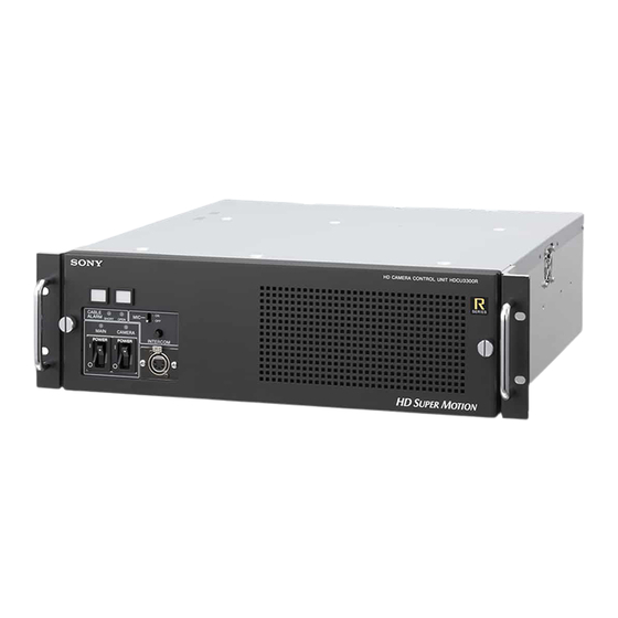
(black burst) signal may be used as the reference signal. The HDCU3300R HD Super Motion Camera Control Unit is to be connected to a Sony HDC3300R HD Super Motion Built-in down converter Color Camera. It carries out signal processing and When the system is operating at a 59.94/50 Hz field... - Page 8 Rack mountable The HDCU3300R may be installed in a standard EIA 19- inch rack (three units high). Plug-in unit configuration Internal printed circuit boards are designed for easy plug- in and removal, which makes it easy to inspect and maintain the unit.
-
Page 9: System Configuration
Production of some of the peripherals and related devices shown in the figures has been discontinued. For advice on choosing devices, please contact your Sony dealer or a Sony sales representative. Basic System Components... -
Page 10: Hd Super Motion/Hd/Sd Signal System
HD Super Motion/HD/SD Signal System VCS-700 PIX/WF HDC3300R+HDLA1500 HDCU3300R + HKCU1001/HKCU1003 MSU-900 series CNU-700 HDCU1000 + HKCU1001/HKCU1003 HDC1000R SD-SDI HDCU1500 + HKCU1001/HKCU1003 HDCU3300R HDC3300R + HKCU1001/HKCU1003 RCP series HD-SDI HDCU1000 + HKCU1001/HKCU1003 HDC1500R HDCU1500 + HKCU1001/HKCU1003 System Configuration... -
Page 11: Precautions
Precautions Installation environments • Avoid extremely hot places or near heating equipment. • Do not place the unit near strong electromagnetic fields. • Place the unit in a dry, well-ventilated place. • Avoid direct sunlight and other strong lighting. Precautions... -
Page 12: Locations And Functions Of Parts
Front Panel 1 Red tally indicator 2 Green tally indicator 3 MIC switch 4 INTERCOM level control HD CAMERA CONTROL UNIT HDCU3300R SERIES 8 INTERCOM connector 7 CAMERA switch and indicator 6 MAIN POWER switch and indicator 5 CABLE ALARM indicators... -
Page 13: Rear Panel
Master Setup Unit. Note The connectors in this area do not supply the color bar For details on the setup menu, contact a Sony service or signals while the power to the video camera is ON (default sales representative. - Page 14 An aspect ratio may also be selected for SD signals. a frequency bandwidth of 5 MHz, regardless of signal format. For details on the setup menu, contact a Sony service or sales representative. 2 REFERENCE connectors (BNC-type) Input an HD tri-level reference sync signal or SD reference Refer also to the Master Setup Unit manual.
-
Page 15: Hkcu1001 Sd Encoder Unit (Optional)
R, G, and B signals in sequential mode. When both the RCP and MSU are in use, For details on installation, contact a Sony service or sales this connector functions as the output connector for RCP representative. -
Page 16: Hkcu1003 Multi Interface Unit (Optional)
The phase is advanced or delayed only while the switch is VDA rear boards (A/B/C). Only the VDA-A board can held pressed. actually be used with the HDCU3300R at present, and the HKCU1003 has almost the same function as the HKCU1001. - Page 17 a VBS 1, 2 (composite video output 1, 2) connectors EN-B Board (BNC-type) The signal from the video camera may be output as two analog composite video signals. b PIX OUT (picture monitor output) connector EN-B (BNC-type) NTSC 1 SD signal format indicators Outputs the video signal for a picture monitor selected with the PICTURE MONITOR button of an RCP-700/ 900-series Remote Control Panel or MSU-900-series...
-
Page 18: Hkcu1005 Sdi Output Expansion Unit (Optional)
SDI OUT 1, 2, 3, 4 (HD/SD serial digital interface output 1 to 4) connectors (BNC-type) For details on installation, contact a Sony service or sales The signal from the video camera is supplied as four HD- representative. -
Page 19: Internal Switches And Internal Boards
c Headset microphone switch 1 (S4) Internal Switches and Set the switch according to the type of microphone of the headset connected to the INTERCOM connector on the Internal Boards front panel of this unit: CARBON: Carbon microphone (power supply, 20 dB gain) ECM: Electret condenser microphone (power supply, 40 CAUTION... - Page 20 AVP Board To insert a “Memory Stick” Insert the “Memory Stick” into the slot so that the labelled side of the stick faces you. When the “Memory Stick” is correctly set, the ACCESS indicator lights in green. If the indicator stays dark, the “Memory Stick”...
- Page 21 CPU Board DTX Board 1 ACCESS indicator 1 Optical condition indicators 2 “Memory Stick” slot CHARACTER DISP 2 Menu control switch MENU CANCEL 3 CANCEL/ENTER switch ENTER 4 +/– switch a ACCESS indicator a Optical condition indicators Shows the status of the “Memory Stick.” The corresponding LEDs light to show the condition of optical signal reception at this unit (CCU) and the camera Indication...
- Page 22 DPR A Note 1080 720P The 30, 25, and 24 indicators do not function on the HDCU3300R. MODE 1 Output signal format indicators DRX Board 1080 a Output signal format indicators 720P Displays the format status of the output signal.
-
Page 23: Specifications
Power supply 100/120/220-240 V AC, 50/60 Hz • TALLY (R, G) (To change to a different power RCP/CNU 8-pin multi-connector (1) supply, contact a Sony service or sales TRUNK A 12-pin (1) representative.) TRUNK LINE D-sub 9-pin, female (1) Current consumption RS-232C, for CHU transmission or 5.6 A (max.) - Page 24 SS-B OUT BNC-type (2) Caution on the optical/electric composite cable: HD-SDI: SMPTE 292M, 0.8 Vp-p, For connection between the camera control unit and a 75 ohms, 1.485 Gbps/1.4835 Gbps camera, be sure to use an optical/electric signal composite SS-C OUT BNC-type (2) cable with the connectors specified in this manual in order HD-SDI: SMPTE 292M, 0.8 Vp-p,...
-
Page 25: Hkcu1001 (Optional)
BNC-type (1), VBS/R/G/B/SEQ VDA-A board: Approx. 0.10 kg (3.5 oz) (VBS 1.0 Vp-p, 75 ohms) Output connectors VDA-C board (not used for the HDCU3300R) BNC-type (1), 1.0 Vp-p, 75 ohms, VBS VDA-A board R/R-Y, G/Y, B/B-Y BNC-type (2), 1.0 Vp-p, 75 ohms, VBS... - Page 26 Design and specifications are subject to change without notice. Note Always verify that the unit is operating properly before use. SONY WILL NOT BE LIABLE FOR DAMAGES OF ANY KIND INCLUDING, BUT NOT LIMITED TO, COMPENSATION OR REIMBURSEMENT ON ACCOUNT OF THE LOSS OF PRESENT OR...
- Page 27 The material contained in this manual consists of information that is the property of Sony Corporation and is intended solely for use by the purchasers of the equipment described in this manual. Sony Corporation expressly prohibits the duplication of any...
- Page 28 Sony Corporation Printed in Japan 2009.02 13 HDCU3300R (CED/E2/E3/UC5) 4-140-781-01(1) © 2009...