
Related Manuals for Sony HKCU2040


Summary of Contents for Sony HKCU2040
- Page 1 HD CAMERA CONTROL UNIT HDCU2000 HDCU2500 4K/HDR PROCESSOR BOARD HKCU2040 3G/HD SDI OUTPUT EXPANSION UNIT HKCU2007 SD ENCODER UNIT HKCU1001 MULTI INTERFACE UNIT HKCU1003 OPERATION MANUAL [English] 1st Edition (Revised 5)
-
Page 2: Table Of Contents
HDCU2000 Rear Panel ........... 9 HDCU2500 Front Panel ..........12 HDCU2500 Rear Panel ..........14 Internal Switches ............16 HKCU2040 4K/HDR Processor Board (optional) ..16 HKCU2007 3G/HD SDI Output Expansion Unit (optional) ..............16 HKCU1001 SD Encoder Unit (optional) ......17 HKCU1003 Multi Interface Unit (optional) ..... -
Page 3: Overview
The HDCU2000/2500 Camera Control Unit is connected to a With multiple boards of this type installed, the HDCU2000/ Sony HD-series high-definition video camera. It carries out 2500 outputs up to 16 (HDCU2000) or seven (HDCU2500) signal processing and provides an interface for external 3G-SDI/HD-SDI signals. - Page 4 RTS/Clear-Com intercom systems. For information on support for RTS/Clear-Com systems, contact a Sony service or sales representative. Remote control The level and phases of this unit’s output signals can be controlled remotely by an MSU-1000 series Master Setup Unit.
-
Page 5: System Configuration
System Configuration Basic System Components RCP-1000 series MSU-1000 series Master Setup Unit Remote Control Panel LAN cable LAN cable Camera Control Unit Camera Optical fiber cable HDC2500 HD Color Video HDCU2000 HDCU2500 Camera HD Camera Control Unit HD Camera Control Unit HDVF-20A/200/EL20/EL30 HD Electronic Viewfinder Camera Control Unit... -
Page 6: System Operation Example
System Operation Example Image monitor HD-SDI Video monitor HDCU2000 HDC2500 LCD monitor LAN cable LAN cable HDCU2500 MSU-1000 series HD-SDI HDCU2000 HDC2500 HDCU2500 CCA-5 cable RCP-1000 series CCA-5 cable... -
Page 7: Locations And Functions Of Parts
Locations and Functions of Parts HDCU2000 Front Panel 2 3 4 a Red tally indicator e INTERCOM audio input/output and control block Lights in red when this unit receives a red tally signal. When MIC/PGM (microphone/program) switch the CALL button on the MSU-1000 series Master Setup Unit, RCP-1000 series Remote Control Panel, etc., is pressed, this INTERCOM (intercom select) switch indicator will go out if previously lit, and light up if previously... - Page 8 To use a headset with a plug other than an XLR 5-pin plug, switch is turned on. Press the top side to turn on the video consult a Sony service or sales representative. camera and the bottom side to turn it off.
-
Page 9: Hdcu2000 Rear Panel
SD signal. the OUTPUT3 and OUTPUT4 connectors can be superimposed character and marker signals. For details on the setup menu, contact a Sony service or sales Signals of the same format are output from the SDI 1 and SDI representative. - Page 10 Sony service or sales representative. or using the MSU-1000 series Master Setup Unit. n WF REMOTE (waveform monitor remote) connector For details on the setup menu, contact a Sony service or sales (D-sub 15-pin) representative. Used to attach to the appropriate connector on a recall-type...
- Page 11 Note Use of a D-sub case wider than 42 mm can cause interference at connectors 2, 4, 5. It is recommended that you use a JAE-made DA-C1-J10. r AUX REMOTE connector (round 8-pin) This is used to connect a sub-camera RCP for operating a sub-camera.
-
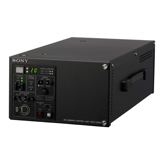
Page 12: Hdcu2500 Front Panel
HDCU2500 Front Panel a Red tally indicator When the second lamp from the right (green) is lighted: Lights in red when this unit receives a red tally signal. When Reception status is good. the CALL button on the MSU-1000 series Master Setup Unit, When the second lamp from the left (yellow) is lighted: RCP-1000 series Remote Control Panel, etc., is pressed, this Reception status is low. - Page 13 CANCEL/ENTER To use a headset with a plug other than an XLR 5-pin plug, consult a Sony service or sales representative. lever to the ENTER position. g CABLE ALARM indicators j Network indicator OPEN (red): Lights in red when a camera isn’t connected to...
-
Page 14: Hdcu2500 Rear Panel
MSU-1000 series Master Setup Unit. For details on installation, contact a Sony service or sales representative. For details on the setup menu, contact a Sony service or sales representative. b HD/SD SDI OUTPUT (SDI output connectors) area... - Page 15 75 ohms. If the signal used is a 1.0 Vp-p, 75-ohm signal, it may be output from the PROMPTER For details on the setup menu, contact a Sony service or sales OUT connector of the video camera with a frequency representative.
-
Page 16: Internal Switches
To adjust the internal settings, refer to qualified service personnel. HKCU2007 3G/HD SDI Output The HKCU2040 4K/HDR Processor Board consists of a DPR Expansion Unit (optional) front board, a DIF rear board and an HIF rear board. The HIF-57 board is required for exchanging the HIF-26 board only when HDCU2500 is installed. -
Page 17: Hkcu1001 Sd Encoder Unit (Optional)
HDCU2000/2500’s expansion slots. VDA-A The format of SDI signals output via each upper/lower pair of connectors on the HIF board can be set. For details on installation, contact a Sony service or sales representative. HIF-57 Board SDI OUT a VBS 1, 2 (composite video output 1, 2) connectors... - Page 18 C board in an expansion slot on the rear panel of the HDCU2000/2500. Don’t insert any board in the corresponding expansion slot on the front of the HDCU2000/2500. For details on installation, contact a Sony service or sales representative. VDA-A Board...
- Page 19 a VBS (composite video signal output) connector (BNC- type) The signal from the video camera may be output as an analog composite signal. b R/R-Y, G/Y, B/B-Y (component video signal output) connectors (BNC-type) The signal from the video camera may be output as a R/R-Y, G/Y, B/B-Y component signal or an RGB component signal.
-
Page 20: Connections And Settings
Connections and Settings Fiber Transmission System of Dual Link Format The camera and the camera control unit are connected via a single optical fiber cable, and transmission is achieved at “High Bit Rate.” Connection example 1 Optical fiber cable (High Bit Rate) HDC2500 HD prompter source Reference... - Page 21 Connection example 2 Optical fiber cable (High Bit Rate) HDC2500 HD prompter source Reference (HD-SDI) LEVEL LEVEL PROD PROD REAR INCOM REAR INCOM signal FRONT FRONT INTERCOM 1 INTERCOM 2 HD PROMPTER IN REFERENCE CAMERA DC OUT EARPHONE REMOTE TRACKER CRANE SDI OUT 1 PROMPTER...
-
Page 22: Coaxial Connection System
COAXIAL Connection System The camera and the camera control unit is connected via two Note coaxial cables in place of an optical fiber cable, and Do not connect an optical fiber cable in a COAXIAL connection transmission is achieved with HD-SDI. system. -
Page 23: Dual-Camera System
Dual-Camera System Two pairs of cameras and camera control units are connected Notes via an optical fiber cable for “High Bit Rate” transmission. • The primary camera and the secondary camera must be in genlock status. • Do not connect any optical fiber cable to the secondary system. -
Page 24: Sub-Camera System
Sub-Camera System Use an HDC-P1, etc. as the sub camera, which can be Note controlled via the AUX REMOTE connector of the HDCU2000. AES/EBU signal cannot be used between the camera and camera control unit. Connection example Main camera (HDC2000) Optical fiber cable (High Bit Rate) Sub camera signal output HD TRUNK OUT... -
Page 25: 4K/Hdr Output System
4K/HDR output system Available only when a slot is installed to the HKCU2040 4K/ HDR Output Processor Board (optional). Connection example 1 Optical fiber cable (High Bit Rate) HDC2500 HD prompter source Reference (HD-SDI) signal HDCU2000 Network cable Switcher Monitor... - Page 26 Connection example 2 Optical fiber cable (High Bit Rate) HD prompter HDC2500 Reference source (HD- signal SDI) HDCU2500 Network cable Switcher Monitor (3G-SDI Quad (3G-SDI Quad Link) Link) RET (VBS/SD-SDI/HD-SDI/3G-SDI) RET (VBS/SD-SDI/HD-SDI/3G-SDI) MSU-1000/1500 RET (VBS/SD-SDI/HD-SDI/3G-SDI) Master Setup Unit RCP-1500/1501/1530 Remote Control Panel Settings Camera MAINTENANCE menu, <CAM MODE>...
-
Page 27: Status Display
Camera settings Status Display Page 1 The CCU system status can be monitored using a picture monitor connected to the PIX output. 1/ 20 0 0 OF F For information on monitoring and changing settings, see “Setup Menu” on page 32. Displaying the Status Screen The status screen is controlled using the knob and levers in ND : 1 F: 4 .7 E X... - Page 28 BLK: Black balance R/G/B/Master value CCU hardware diagnostics BLK γ: Black gamma value FLR: Flare balance R/G/B/Master value 2/2 0 DTL: Detail level Page 3 ** Dia gno si s * * A: AT 2:D RX B: AV P 3:D RX S D Mat rix: ON C: DT X 4:R C...
- Page 29 RCP/CNU Power: Power supply status to a device connected CNS Mode: REMOTE and LAN connectors mode setting to this unit’s REMOTE connector status CCU No.: CCU number setting status Page 3 Master IP Address: Master device IP address Page 3 * S y ste m Diag 3/3* 5/ 20 I n t erc om...
- Page 30 1 4/2 0 PL D Version:1.00 Don e Re a r :HIF Power: OK When the HKCU2040 board is installed Fr ont :No ne P owe r:O K * S l ot1 Diag* 1 2/ 20 PL D V ers ion :1 .00 D one 1 &...
- Page 31 Camera hardware diagnostics Note The items displayed differ depending on board connected to *CA MER A D ia g* 1 9/2 0 the expansion slot. ALL B OAR D O K Status of the board inserted in Slot5 (HDCU2000 only) * E N -B( Slot5) Diag* 1 6/ 20 S u b -Ref:None Unknow n...
-
Page 32: Setup Menu
The pointer (,) changes to a flashing question mark (?). Setup Menu Flashing <OU TPU T S EL ECT > ? S01 TO P The CCU system and peripheral settings can be checked and modified using a picture monitor connected to the PIX output. OU TPU T:* CA MER A BA R TE ST1... - Page 33 Turn the CONTROL knob to move the cursor to the desired character, then press the CONTROL knob. Repeat steps 1 and 2 to enter other characters. • Select INS to insert a space character at the cursor position. • Select DEL to delete the character at the cursor position.
-
Page 34: Menu Tree
Menu Tree SYSTEM OPERATION menu 3D SETTINGS 3D MODE (S09) 3D OUTPUT OUTPUT SELECT OUTPUT 3D MONITOR (S01) POSITION GENLOCK PHASE CONTROL MIX CHROMA REFERENCE DIFF MODE (S02) GENLOCK V SPLIT MODE H STEP BORDER LINE OARSE CHANNEL ID SC PHASE 4K/HDR HDR MODE V PHASE... - Page 35 CCU CONFIGURATION menu PROMPT/TRUNK 1 PROMPTER CH TRUNK LINE COLOR BAR 4K/HD-BAR (C10) (C01) MF CB SLOPE RATE SD-BAR AUX REMOTE 2SI DIA MARKER NETWORK TRUNK PROMPT/TR UNK 2 MODE BAR-CHARA (C11) GRAY RATE MOVING SYMBOL HD PROMPTER TYPE FRAME SYNC SIZE HD TRUNK BAR CHARACTER...
- Page 36 NETWORK SETTINGS menu SPIRIT LEVEL INDICATOR IP ADDR SET HOST IP ADDRESS REVERSE (C21) (N01) SUB NET MASK H POSITION DEFAULT GATEWAY V POSITION BOARD SETUP BOARD SELECT LAN SETTINGS AUTO NEGOTIATION (C22) EMBED AUDIO (N02) AUTO MDIX META DATA EMBED CONNECT CONFIGURATION PAYLOAD ID CONNECT SPEED...
-
Page 37: Menu List
Menu List Note The following conventions are used in the menu list table. Settings column values (e.g. ON, OFF, 0): Default settings Execute via ENTER: Press the CONTROL knob or move the CANCEL/ENTER lever to the ENTER position to execute. SYSTEM OPERATION menu SYSTEM OPERATION Page name... - Page 38 SYSTEM OPERATION Page name Item Settings Description Page No. <MULTI FORMAT> FREQUENCY 1.001, 1.000 Selects the operating frequency. (525NTSC), (625PAL) Note CAMERA FORMAT When FREQUENCY is set to Selects the transmission format. • FREQUENCY or 1.001: 1080/59.94I, 1080/ CAMERA FORMAT 29.97PsF, 1080/59.94P, 1080/ mode setting changes 23.98PsF, 720/59.94P, 1080/...
- Page 39 Selects the output format for expansion slot 1’s SDI OUT3/4 connector. OETF S-Log3, HLG_BT.2100, HLG_Live, Selects OETF for expansion slot 1. (Displayed only when HKCU2040 is installed.) COLOR BT.2020, BT.709 Selects COLOR SPACE for expansion slot 1. (Displayed only when HKCU2040 is installed.) SLOT2 (board name) 1&2...
- Page 40 * Use the charts on the following as an example of how to configure these settings. The settings differ depending on the boards connected to the expansion slots. 1080/59.94I 1080/29.97PsF 1080/59.94P 1080/23.98PsF 720/59.94P 1080/59.94I (RGB444) Slot1 1&2 1080/59.94I 1080/29.97PsF 1080/59.94P 1080/23.98PsF 720/59.94P 1080/59.94I...
- Page 41 1080/25PsF 1080/24PsF 1080/50I 720/50P 1080/50P (RGB444) (RGB444) (2×) (2×) (4K/HDR) Slot1 1&2 1080/25PsF 1080/24PsF 1080/50I 720/50P 4K/50P(2SI) (RGB444) (3G) (RGB444) (3G) (2×) (3G) (2×) (3G) OETF: HLG_Live COLOR: BT.2020 Slot1 3&4 M1080/25PsF C1080/24PsF C1080/50I C720/50P 4K/50P(2SI) (RGB444) (3G) (RGB444) (A) (2×) (3G) (2×) (3G) OETF: HLG_Live...
- Page 42 SYSTEM OPERATION Page name Item Settings Description Page No. <SD ASPECT> SD ASPECT SQUEEZE, EDGE CROP, LETTER Selects the SD output aspect. SD LB SEL 16:9, 15:9, 14:9, 13:9 Selects the LETTER BOX aspect ratio. H-POSITION –99 to 99, (–99) to (99), 0 Sets the horizontal position.
- Page 43 OUTPUT FORMAT RETURN FORMAT 1080/59.94I 1080/59.94I (PsF), 525/59.94I (PsF), NTSC 1080/29.97PsF 1080/59.94P, 1080/59.94P 1080/59.94P, 1080/59.94I (PsF), 720/59.94P , 525/59.94I (PsF), NTSC (4K/HDR) 1080/23.98PsF 1080/23.98PsF, 1080/59.94I (PsF), 525/59.94I (PsF), NTSC 720/59.94P 720/59.94P, 525/59.94I (PsF), NTSC 1) 2) 1080/59.94I (RGB444) 1080/59.94I (PsF) (RGB444) , 1080/59.94I (PsF), 525/59.94I (PsF), NTSC 1080/29.97PsF (RGB444) 1) 2)
- Page 44 OFF, LIVE HDR OFF: Normal SDR shooting mode LIVE HDR: Extends the imaging dynamic range of camera and outputs enhanced HDR videos. (Available when an HKCU2040 board is SDR GAIN 0.0 to –15.0 dB Sets the gain for SDR output. installed) Available only when HDR MODE is set to LIVE HDR.
- Page 45 Sets diamond mark superposition on the color bar for 4K 2 sample interleave output. Note See “4K 2SI diamond marks” (page 46). Displayed only when HKCU2040 is connected BAR-CHARA ON, OFF Turns the signal for characters superimposed on a color bar ON/OFF.
- Page 46 CONFIGURATION Page name Item Settings Description Page No. 4K 2SI diamond marks This function is for displaying a test pattern like the following in the area at the bottom right of the 4K color bar when 4K 2 sample interleave output. OK is displayed if the connections for Links 1 to 4 are correct, and OK is not displayed if they are incorrect.
- Page 47 CONFIGURATION Page name Item Settings Description Page No. <MONITOR 2> LEVEL GATE ---, 1&2, 1, 2, OFF 1&2: Displays level gate 1 & 2. 1: Displays level gate 1. 2: Displays level gate 2. ---: Displayed when camera not connected, video output not set to CAMERA, or video output is set to CAMERA and GATE MARKER is ON.
- Page 48 CONFIGURATION Page name Item Settings Description Page No. <INTERCOM> INTERCOM CH 1CH, 2CH Selects the intercom channel number. SYSTEM INTERFACE PRODUCER 4WIRE, RTS, CLEAR COM Sets the producer line intercom system. CANCEL LVL –99 to 99, 0 Sets the side tone cancel level. Connects to a 200 Ω...
- Page 49 CONFIGURATION Page name Item Settings Description Page No. <PROMPT/TRUNK 1> PROMPTER CH 1CH, 2CH Sets the number of prompter lines. (HDCU2500 is locked to 1CH.) TRUNK LINE 1CH, 2CH Sets the number of channels to be used. 232C, 422A Sets the communication line mode. RATE (38Kbps), (19Kbps), (75Kbps), Displays the TRUNK line.
- Page 50 CONFIGURATION Page name Item Settings Description Page No. (Available when yet G/Y LEVEL –99 to 99, 0 Adjusts the G/Y output video level. another VDA board from B/B-Y LEVEL –99 to 99, 0 Adjusts the B/B-Y output video level. the HKCU1003 is installed R/R-Y LEVEL –99 to 99, 0 Adjusts the R/R-Y output video level.
- Page 51 Adjusts the vertical position. <BOARD SETUP> BOARD SELECT DRX1, DRX2, DRX3, DRX4, RC, Selects the board to set. (DPR) (DPR): Only when an HKCU2040 board is installed. EMBED AUDIO ON, OFF Sets superimposition of audio data to ON/OFF. META DATA OFF, ON Sets superimposition of metadata to ON/OFF.
- Page 52 NETWORK SETTINGS menu NETWORK SETTINGS Page name Item Settings Description Page No. <IP ADDR SET> HOST IP ADDRESS 0.0.0.0 to 255.255.255.255 Displays the IP address. SUB NET MASK 0.0.0.0 to 255.255.255.254 Displays the subnet mask. DEFAULT GATEWAY 0.0.0.0 to 255.255.255.255 Displays the default gateway.
-
Page 53: Appendix
Error Messages Appendix When an error is detected in this unit or the camera, the ALARM indicator turns on and an error message is displayed on this unit. Notes on Use Error message Indication CCU:GEN LOCK NG External reference sync error Use and storage locations CCU:DRX NG Front DRX board power supply,... -
Page 54: Specifications
NETWORK TRUNK 8-pin (1) Input connectors AC IN (1), 100/120/220-240 V HDCU2000 (To change to a different power supply, contact a Sony service or sales representative.) General SDI RET IN BNC-type (4) Power supply 100/120/220-240 V AC, 50/60 Hz 3G-SDI: SMPTE ST424/ST425, 2.970 Gbps/2.967 Gbps... -
Page 55: Hdcu2500
USA and Canada: 1-551-812-XX Other countries: 1-782-929-XX Power cord plug holder USA and Canada: 2-990-242-01 Other countries: 3-613-640-01 HKCU2040 4K/HDR Processor Board HKCU2007 3G/HD SDI Output Expansion Unit HKCU1001 SD Encoder Unit HKCU1003 Multi Interface Unit CCA-5-3 Connection Cable (3 meters/10 feet) - Page 56 USA and Canada: 2-990-242-01 Output connectors Other countries: 3-613-640-01 AUDIO OUT CH1, XLR 3-pin, male (2), 0 dBu/–20 dBu/+4 dBu HKCU2040 4K/HDR Processor Board 3G/HD SDI OUTPUT BNC-type (2) HKCU2007 3G/HD SDI Output Expansion Unit 3G-SDI: SMPTE ST424/ST425, 0.8 Vp-p, HKCU1001 SD Encoder Unit 75 ohms, 2.970 Gbps/2.967Gbps...
-
Page 57: Hkcu2040 (Optional)
HKCU2040 (optional) HKCU2007 (optional) General General Power supply 23.5 W Power supply 5.5 W Operating temperature –10°C to +40°C (+14°F to 104°F) Operating temperature –10°C to +40°C (+14°F to 104°F) Storage temperature –20°C to +60°C (–4°F to 140°F) Storage temperature –20°C to +60°C (–4°F to 140°F) -
Page 58: Hkcu1003 (Optional)
Design and specifications are subject to change without notice. Note Always verify that the unit is operating properly before use. SONY WILL NOT BE LIABLE FOR DAMAGES OF ANY KIND INCLUDING, BUT NOT LIMITED TO, COMPENSATION OR REIMBURSEMENT ON ACCOUNT OF THE LOSS OF PRESENT OR PROSPECTIVE... - Page 59 Sony Corporation HDCU2000 (UC/CE/E) HDCU2500 (SY) 4-413-603-06(1) © 2011...