Table of Contents
Advertisement
Advertisement
Table of Contents

Related Manuals for Bosch FCP-320


Summary of Contents for Bosch FCP-320
- Page 1 Conventional Automatic Detectors FCP-320/FCH-320 Operation Guide...
-
Page 3: Table Of Contents
Accessories for Service und Detector Testing Order Overview Detector Variants 6.1.1 Detectors with 820 Ohm Alarm Resistor 6.1.2 Detectors with 470 Ohm Alarm Resistor* Detector Bases Detector Accessories Installation Accessories Detector Base Sounders Bosch Sicherheitssysteme GmbH Operation Guide F.01U.002.707 | 8.0 | 2011.10... -
Page 4: En | Table Of Contents
Conventional Automatic Detectors Service Accessories Maintenance and Service Coding of the Detector Types Test Procedure for Detectors with C-Sensor Test Procedure for Detectors without C-Sensor Warranty Repair Disposal Additional Documentation Specifications Abbreviations F.01U.002.707 | 8.0 | 2011.10 Operation Guide Bosch Sicherheitssysteme GmbH... -
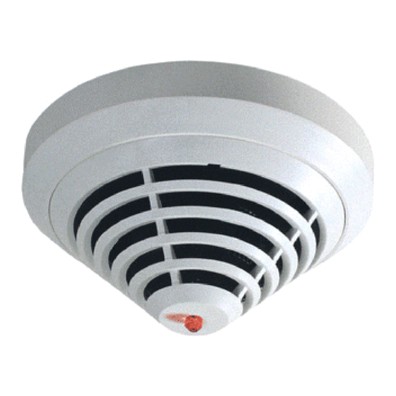
Page 5: Product Description
This Product Information describes the entire product range of the FCP-320/FCH-320 Conventional Automatic Fire Detectors. The FCP-320/FCH-320 Conventional Automatic Fire Detectors works on the basis of the conventional technology and combines standard detection methods such as scattered light measurement and temperature measurement with gas measuring technology at the highest configuration level. -
Page 6: System Overview
The gas sensor supplies additional information in order to reliably suppress deception variables. Figure 2.2 Chemical Sensor System Description Up to two detection principles are integrated into the FCP-320/FCH-320 Series Fire Detectors: – Optical (for smoke): O –... -
Page 7: Features
(not required for the FCH-T 320/ FCH-T 320-R470/FCH-T 320-FSA Heat Detectors). – Connectable to Bosch fire panels and the majority of conventional fire panels available on the market. – Two variants with 820 Ω alarm resistor and 470 Ω alarm resistor enables the detector application with nearly all conventional fire panels. -
Page 8: Planning
| Planning Conventional Automatic Detectors Planning NOTICE! FCP-320/FCH-320 Conventional Automatic Fire Detectors are not designed for exterior use. Basic Planning Guidelines – The planning of multisensor fire detectors takes place according to the guidelines for optical detectors, until an independent guideline has been worked out with the VdS (see DIN VDE 0833 Part 2 and VDS 2095): –... -
Page 9: Installation
Installation Overview of Detector Bases The FCP-320/FCH-320 Series detector head is used in one of the following listed detector bases, which are suitable for both flush-mounted and surface-mounted cable feed. They have separate attachment points for ceiling mount/flush-mounted back boxes. In addition, they fit all standard bore patterns. - Page 10 The additional base has a diameter of 120 mm and a height of 36.7 mm. To protect against condensed water penetration, a seal made of TPE is situated on the base of the MSC 420. F.01U.002.707 | 8.0 | 2011.10 Operation Guide Bosch Sicherheitssysteme GmbH...
-
Page 11: Mounting The Bases
Cable feed and outfeed can be on the same side. For cable feed at the FAA-420-SEAL and MSC 420 puncture the sealing with a pointed tool. Do not cut the sealing with a knife. Ø 120 Ø 100 Bosch Sicherheitssysteme GmbH Operation Guide F.01U.002.707 | 8.0 | 2011.10... -
Page 12: Wiring
Indicator output +V / 0V Terminals for looping through the power supply to subsequent elements MPA / FAA-420- External Detector Alarm Display / Remote Indicator F.01U.002.707 | 8.0 | 2011.10 Operation Guide Bosch Sicherheitssysteme GmbH... -
Page 13: Wiring The Msr 320
- / L..a (conventional) MPA/FAA-420-RI: red, connects to b1 MPA/FAA-420-RI: black, connects to c (Indicator output) green, connects to shielding wire NC / C / NO Changeover relay (for the MSR 320 only) Bosch Sicherheitssysteme GmbH Operation Guide F.01U.002.707 | 8.0 | 2011.10... -
Page 14: Detector Base Sounder
The detector head can be locked into the base (removal protection). The locking feature is activated by breaking the bolt (X) out of the base and pushing it into the corresponding guide, as shown in Figure 4.1. F.01U.002.707 | 8.0 | 2011.10 Operation Guide Bosch Sicherheitssysteme GmbH... -
Page 15: Detector Removal
(Y) so that the bolt is pushed upward; at the same time, the detector head should be turned to the left (refer to Figure 4.2). Figure 4.2 Detector Removal (Locked Detector) Bosch Sicherheitssysteme GmbH Operation Guide F.01U.002.707 | 8.0 | 2011.10... -
Page 16: Accessories
If the detector is mounted in a sports facility, for example, the protective basket prevents balls or other sports equipment from hitting the detector and damaging it. F.01U.002.707 | 8.0 | 2011.10 Operation Guide Bosch Sicherheitssysteme GmbH... -
Page 17: Ssk 400 Protective Dust Cover
The remote indicators should be installed in corridors or access pathways to the corresponding building sections or rooms. The red alarm indication of both FAA-420-RI and MPA correspond to DIN 14623. Bosch Sicherheitssysteme GmbH Operation Guide F.01U.002.707 | 8.0 | 2011.10... -
Page 18: Remote Indicator Faa-420-Ri
FAA-420-RI Remote Indicator.You should restrict the maximum detector current consumption to 20 mA to avoid damaging the FAA-420-RI. All current Bosch fire detectors are equipped with an internal resistor to restrict current consumption. F.01U.002.707 | 8.0 | 2011.10... -
Page 19: External Detector Alarm Display Mpa
Connect: Put in the isolated wire (no braid) into the clamp. Disconnect: Pull the wire out of the clamp by turning it back and forth. You can connect up to four detectors onto each MPA. Bosch Sicherheitssysteme GmbH Operation Guide F.01U.002.707 | 8.0 | 2011.10... - Page 20 Connect onto terminal 4 only via pre resistor, otherwise the LED could 1 2 3 4 be destroyed. All current Bosch fire detectors are equipped with an internal resistor to restrict current consumption. CAUTION! If the current consumption for the connected detector exceeds 20 mA, it can lead to the malfunction of or damage to the MPA External Detector Alarm Display.
-
Page 21: Accessories For Service Und Detector Testing
Detectors DU = 12 pieces SOLO CO Testing Gas Spray with CO testing gas for multisensor detectors with C component. Contents: approx. 4 l compressed gas DU = 12 pieces Bosch Sicherheitssysteme GmbH Operation Guide F.01U.002.707 | 8.0 | 2011.10... - Page 22 Safety compliance in accordance with the requirements of BS EN 61235 Section 12 using an applied voltage of 20 kV. Length: 1 m to 3.4 m F.01U.002.707 | 8.0 | 2011.10 Operation Guide Bosch Sicherheitssysteme GmbH...
- Page 23 The SOLO610 Test Equipment Bag is made of sturdy woven polyester with a PVC coating for carrying and storing test and service products. It is designed with special compartments to hold a full range of products. Bosch Sicherheitssysteme GmbH Operation Guide F.01U.002.707 | 8.0 | 2011.10...
-
Page 24: Order Overview
Standard Detector Base for surface-mounted and 4.998.021.535 flush-mounted cable feed MS 400 B Standard Detector Base for surface-mounted and F.01U.215.139 flush-mounted cable feed, with Bosch-branding FAA-420-SEAL Damp Room Seal for the MS 400 and MS 400 B F.01U.215.142 Detector Bases MSR 320 Conventional Detector Base with Relay for surface- 4.998.114.565... -
Page 25: Installation Accessories
Battery for SOLO461 Heat Detector Tester 4.998.147.576 FME-TESTIFIRE Multi-Stimulus Testing Tool F.01U.143.407 FME-TS3 Smoke Capsule F.01U.143.404 FME-TC3 CO-Capsule F.01U.143.405 SOLO100 Telescopic Access Pole 4.998.112.069 SOLO101 Fixed Extension Pole 4.998.112.070 SOLO610 Test Equipment Bag 4.998.112.073 Bosch Sicherheitssysteme GmbH Operation Guide F.01U.002.707 | 8.0 | 2011.10... -
Page 26: Maintenance And Service
DIN VDE 0833; these regulations stipulate reference to the manufacturer's instructions for maintenance intervals. – Maintenance and inspection work should be carried out regularly and by trained personnel. – BOSCH ST recommends a functional and visual inspection at least once a year. Testing Detector Type FCP-O320 FCH-T320 FCP-OT320... - Page 27 30 to 35 ppm is required when the chemical sensor is tested. This is guaranteed if the test is performed with the CO Test Gas bottle as described. Bosch Sicherheitssysteme GmbH Operation Guide F.01U.002.707 | 8.0 | 2011.10...
-
Page 28: Disposal
Defective detectors are exchanged and should be disposed of in accordance with statutory regulations. Additional Documentation NOTICE! The latest Product Information and the Installation Guide for the device are available as a downloadable PDF file at http://www.boschsecurity.com/emea/fire. F.01U.002.707 | 8.0 | 2011.10 Operation Guide Bosch Sicherheitssysteme GmbH... -
Page 29: Specifications
ABS / white, similar to RAL 9010, matte surface Weight without packaging approx. 80 g approx. 75 g Weight with packaging approx. 125 g approx. 115 g Product ID F.01U.026.292/F.01U.026.867 F.01U.026.295/F.01U.026.862 Bosch Sicherheitssysteme GmbH Operation Guide F.01U.002.707 | 8.0 | 2011.10... - Page 30 Rise [K min Lower Limiting Upper Limiting Lower Limiting Upper Limiting Value [min/sec] Value [min/sec] Value [min/sec] Value [min/sec] 1 min 4 min 20 s 2 min 5 min 30 s F.01U.002.707 | 8.0 | 2011.10 Operation Guide Bosch Sicherheitssysteme GmbH...
- Page 31 Universelle Europazentrale (Universal European Fire Panel) Universelle Gefahrenmeldezentrale (Universal Security System) Verband Deutscher Elektrotechniker e.V. (German Association for Electrical, Electronic & Information Technologies) VdS Schadenverhütung GmbH Optical/Thermal/Chemical (gas) Optical/Thermal Optical Thermal Bosch Sicherheitssysteme GmbH Operation Guide F.01U.002.707 | 8.0 | 2011.10...
- Page 34 Bosch Sicherheitssysteme GmbH Robert-Bosch-Ring 5 85630 Grasbrunn Germany www.boschsecurity.com © Bosch Sicherheitssysteme GmbH, 2011...