
Related Manuals for Monogram ZET1PL1SS


Summary of Contents for Monogram ZET1PL1SS
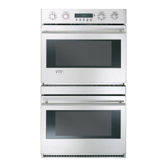
- Page 1 GE Consumer & Industrial Technical Service Guide April 2006 Monogram 30-in. Single and Double Convection Wall Ovens ZET1PL1SS ZET1SL1SS ZET2PL1SS ZET2SL1SS 31-9142 GE Appliances General Electric Company Louisville, Kentucky 40225...
- Page 2 IMPORTANT SAFETY NOTICE The information in this service guide is intended for use by individuals possessing adequate backgrounds of electrical, electronic, and mechanical experience. Any attempt to repair a major ap pli ance may result in personal injury and property damage.
-
Page 3: Table Of Contents
Table of Contents Bake Element ..................................35 Broil Element ..................................26 Component Locator Views ............................14 Component Voltage Test ...............................47 Control Boards Connector Locator ...........................44 Control Compartment Access ............................30 Control Features ................................6 Control Voltage ..................................46 Convection Bake Element .............................28 Convection Fan Assembly ............................28 Cooling Fan ..................................37 Diagnostics and Service Information ........................46 Door Assembly ...................................21... -
Page 4: Introduction
Introduction Monogram introduces the new GE Professional Wall Ovens. Their superior style and performance parallel commercial ovens. Available in two design choices -- integrated and professional -- these ovens feature electronic dial controls that combine the precision of modern digital technology with the simplicity of traditional mechanical controls. -
Page 5: Nomenclature
Model Number Z E T 1 P L 1 S S Product Color SS = Stainless Steel GE Cooking Product ZE = Monogram Electric Indicator for Engineering and Confi guration Product Service Only T = 30-in. Wall Oven Model Year Designator Feature Pack Designates features–the higher... -
Page 6: Control Features
Control Features Double oven control – Pro style shown (Appearance may vary) Single Oven control – Integrated style shown (Appearance may vary) 1 Oven Mode knob – Turn to select: 4 PROBE – Push to select the probe to cook food to a set internal temperature. - Page 7 Oven Controls Overview Oven Mode knob Temperature knob For all modes except Proof, the oven will not To cancel a feature, turn either the Oven operate unless both the Oven Mode and the Mode knob or the Temperature knob to OFF. Temperature knobs are set.
- Page 8 Clock and Control Lockout Power If a flashing time of day is in the display, you have experienced a power failure. failure Reset the clock. Clock The clock must be set for the automatic oven timing functions to work properly. The time of day clock cannot be changed during Delay Start.
- Page 9 Timer Feature NOTE: The timer is independent of all the other Double oven display shown. functions and it does not control the oven. You may program the timer to time cooking or other household activities for up to 11 hours and 59 minutes.
-
Page 10: Special Features
Special Features Special Your oven has additional Special Features that you On double oven models, either the Oven Mode knob or may choose to use. the Temperature knob will have to be turned to OFF for features of each oven. your oven They remain in the control’s memory until the steps are repeated. - Page 11 Special Features 12-hour, Your control is set to use a 12-hour clock. If you Double oven display shown. would prefer to have a 24-hour military time clock or 24-hour black out the clock display, follow the steps below. or clock 1 Push and hold the PROBE and DELAY blackout START buttons at the same time for...
- Page 12 Special Features Sabbath With this feature, should you forget and leave the Double oven display shown. oven on, the control will automatically turn off the Feature, oven after 12 hours during baking functions. If you 12-hour wish to turn off this feature, follow the steps below. shut-off or 1 Push and hold the PROBE and DELAY no shut-off...
-
Page 13: Operational Notes
• Different broil elements are used in each broil Sales Mode mode. There are 3 different broil modes, each providing a HI and a LO setting. The oven control can be operated in SALES MODE. When the unit is connected to 120 VAC from L1–L2, •... -
Page 14: Bake Element
Component Locator Views 30-in. Double Wall Oven (Integrated Stainless shown) Control Panel Broil Element Meat Probe Outlet Convection Fan Lights Lights Hidden Bake Element Oven Door Gasket Oven Door Broil Element Convection Fan Meat Probe Outlet Lights Lights Hidden Bake Element Oven Door Gasket Oven Door (Continued next page) - Page 15 Control Compartment Top Oven Cooling Fan Capacitor Relay Board Power Board Power Vent Assembly Probe Wire Harness Door Lock Right Side Oven Left Side Oven Lights Wire Lights Wire Harness Harness Bottom Oven Cooling Fan Thermal Line Break Thermal Cutout (TCO) Capacitor Left Side Oven Lights Wire...
- Page 16 30-in. Single Wall Oven (Pro Stainless shown) Control Panel Broil Element Convection Fan Meat Probe Outlet Lights Lights Hidden Bake Element Oven Door Gasket Oven Door Control Compartment Thermal Line Break Thermal Cutout (TCO) Cooling Fan Capacitor Left Side Oven Relay Lights Wire Board...
-
Page 17: Oven Component Access Chart
Oven Component Access Chart WARNING: • The single and double wall ovens are heavy and require two people to remove them from the installation. Care should be taken when removing and installing. • Sharp edges may be exposed when servicing. Use caution to avoid injury. Wear Kevlar gloves or equivalent protection. - Page 18 4. Pull the oven slightly forward to access some Oven Removal components (See Oven Component Access Chart or if removing it completely, utilize a table or The replacement of certain components require platform in front of the oven and pull the oven oven removal.
- Page 19 2. On double wall ovens, remove the single Phillips- Oven Separation (Double Wall Oven) head and the four ¼-in. hex-head screws that To separate the double wall oven, remove the hold the heat shield to the side of the oven. access cover attached to the back of the ovens.
- Page 20 3. Remove the eight ¼-in. hex-head screws from 6. Remove the two ¼-in. hex-head screws that each side trim. hold the back of the top oven to the bottom oven. Note: The top of each side trim has a pin that fi ts fi...
-
Page 21: Door Assembly
Oven Components To replace the door: Door Assembly With the door at the same angle as the removal The oven door can be separated into 2 assemblies. position, seat the indentation of the hinge arm The outer assembly consists of the outer panel into the bottom edge of the hinge slot. - Page 22 To remove the outer door assembly: 2. Remove the 4 T-15 Torx screws (2 on each side) that attach each door hinge to the inner door. Remove the door. Carefully turn the door over and remove both door hinges. Place the inner door assembly, gasket side up, on a protective surface.
- Page 23 Remove the eight ¼-in. hex-head screws that Arrows on the side of the inner glass assembly hold the heat barrier to the inner door. Remove indicate the direction in which the inner oven door the barrier. glass is installed. The arrows should be pointing toward the oven cavity.
- Page 24 To install a rack: Oven Racks 1. Place the rear rack locks over and onto the WARNING: To avoid possible burns, remove or install rack supports. (Five rack positions are available the racks before turning on the oven. including the top position.) To remove a rack: 1.
- Page 25 2. Fully extend the rack on a table or countertop. Open and close the rack several times to Newspaper may be placed underneath the distribute the lubricant. rack for easy clean up. Replace the cap on the lubricant and shake it again.
-
Page 26: Oven Temperature Sensor
Note: When reinstalling the sensor, use a small fl at- Oven Temperature Sensor blade screwdriver to push and guide the sensor wire harness into the oven liner. The oven temperature sensor has a resistance of: 1091 Ω at room temperature •... -
Page 27: Vent Tube/Smoke Eliminator
4. Remove the four ¼-in. hex-head screws that Vent Tube/Smoke Eliminator hold the broiler element to the oven cavity. The oven vent tube/smoke eliminator is located in the top left front corner of the oven cavity above Broil Element the broiler element shield. Air vented from the oven cavity will pass through the catalyst, then enter the vent tube of the power vent assembly. -
Page 28: Convection Bake Element
4. Carefully pull the convection bake element Convection Bake Element towards the front of the oven until the element terminals are accessible. • The convection bake element is composed of an inner and an outer element. It is replaced as one unit. - Page 29 The convection fan will turn on (after a short delay). 4. Carefully pull the fan assembly into the oven The fan may cycle on and off, and change direction cavity and disconnect the fan motor wire in any of these modes, to best distribute hot air in harness.
-
Page 30: Control Compartment Access
Control Compartment Access Lower Oven Control Compartment Access (Double Wall Oven) Note: It may be necessary to partially remove the oven from the installation to avoid damage to the To access the lower compartment: customer's woodwork. (See Oven Removal Remove the upper oven door. (See Door To access the control compartment: Assembly... -
Page 31: Logic Board
Logic Board Mode and Temperature Encoders The logic board is mounted to the display frame The mode and temperature encoders are mounted attached to the inside center of the control panel. to the control panel. For ease of access, it may be It is necessary to remove the control panel and the necessary to remove the control panel to replace display frame to replace the logic board. -
Page 32: Power Supply And Relay Boards
Carefully reach into the control compartment Power Supply and Relay Boards and slide the capacitor out of the restraining clamp. The power supply is mounted on a metal bracket located in the control compartment. This power supply serves both ovens on a double oven model. The relay board for the single oven (or the upper oven on a double oven model) is mounted on this same metal bracket. -
Page 33: Lock Assembly
To remove the power supply: Lock Assembly Disconnect the wire harnesses from the power The motorized door lock assembly is located above supply board at locations J13, U12, and the ground the oven. The assembly consists of a lock motor, wire from U15. - Page 34 Lock Assembly Voltage Checks Door Lock - Locked Position Test Wires Locked Unlocked While Unlocking While Locking LOCK Yellow to 2.5 VDC 2.5 VDC 2.6 to 2.9 VDC Switch Orange UNLOCK Switch Yellow to Blue 2.6 to 2.9 5.0 VDC 5.0 VDC DOOR Motor...
- Page 35 3. Remove the two ¼-in. hex-head screws that Bake Element hold the bake element cover to the oven. • The bake element is composed of an inner and an outer element. It is replaced as one unit. • The inside element is rated at 1700 watts, has an approximate resistance value of 33 Ω, and draws approximately 7.3 amps.
- Page 36 IMPORTANT: The lower wattage outer element 8. Grasp and pull the element out from the left side utilizes -in. terminal connections. The higher of the oven. wattage inner element utilizes ¼-in. terminal connections. 5. Disconnect the wires from the bake element. Note: •...
-
Page 37: Lower Oven Control Compartment Access (Double Wall Oven)
Carefully remove the cooling fan from the Cooling Fan control compartment. A cooling fan is located above each oven in the To remove the cooling fan in the lower oven: center rear wall of the control compartment. In a double wall oven, both fans operate together. Access the lower oven control compartment. -
Page 38: Meat Probe And Outlet
Power Vent Assembly and FAD (Fan Meat Probe and Outlet Apparency Device) Each oven is equipped with a meat probe outlet located near the top right front corner of the oven Each oven is equipped with a power vent assembly cavity. -
Page 39: Oven Racks
To remove the FAD: Note: Two holes are provided in the broiler shield to gain access to the 2 screws that attach the power The FAD is held in place by two ¼-in. hex-head vent assembly to the oven frame. screws. -
Page 40: Oven Removal
Thermal Line Break Thermal Cutout (TCO) Oven Light Assemblies The thermal line break TCO is wired in series with Each oven is equipped with two halogen light the common side of all the elements and is used to assemblies located on the side walls of the oven. protect against element runaway. - Page 41 Oven Light Bulbs Using gloves or a dry cloth, remove the burned- out light bulb by pulling it straight out. Caution: • Before replacing the bulb, disconnect electrical power to the oven at the main fuse or circuit breaker panel. •...
- Page 42 Replace the light cover by placing its front edge under the front two tabs in the light housing. Roll the back edge into place, making sure that it is fi rmly seated. Place front edge of Hold locking lens cover under clips in place front two tabs on lens cover...
-
Page 43: Electronic Oven Control
Electronic Oven Control Overview The Electronic Oven Control system consists of the logic/display board, power supply board, relay board, mode and temperature encoders, oven sensor, and door lock assembly. Caution: Components are electrically HOT on control when voltage is connected to range. •... -
Page 44: Control Boards Connector Locator
Control Boards Connector Locator WARNING: Components are electrically HOT when voltage is connected to oven. Control Panel for Double Wall Oven Temperature Logic Board Mode Temperature Mode Encoder Encoder Encoder Encoder Board Board Board Board Control Panel for Single Wall Oven Temperature Logic Board Mode... - Page 45 Power Supply Board and Relay Board J7 J6 J5 J10 J11 J2 J3 J4 J2 - Broil Outer Element K1 - Outer Broil Relay K2 - Outer Bake Relay J3 - Bake Outer Element K3 - Double Line Break Relay J4 - Convection Inner Element K4 - Oven Light Relay J5 - Bake Inner Element...
-
Page 46: Control Voltage
Diagnostics and Service Information Service Test Mode (Factory Test Mode in Mini-Manual) The electronic control system components may be tested individually for troubleshooting purposes. To enter service test mode, the unit must be restarted. Within 5 minutes of restart, press the Push to ENTER knob, COOK TIME and DELAY START buttons simultaneously and hold for 3 seconds. -
Page 47: Component Voltage Test
Component Voltage Test The voltage applied to certain components can be tested individually. Enter the Service Test Mode and select the step for the operation of the desired component. Check for proper voltage on the relay board as described in the table and shown on the diagram below. Note: •... -
Page 48: Oven Sensor And Door Switch Test
Oven Sensor and Door Switch Test Note: See for door switch function explanation. Lock Assembly Remove power from oven. Make resistance measurement from side of sensor and lock switch connector with exposed terminals. The resistance measurements are made on the logic board at connector CN2 (single/upper oven) and CN1 (lower oven-double wall oven only). -
Page 49: Error Codes
Error Codes The electronic oven control has error (F) codes that can be utilized by the service technician in order to quickly identify failed or improper operation of certain oven components. The oven may stop operating but not give an F code on the display immediately. F codes are stored in nonvolatile EEPROM memory until the same fault occurs twice consecutively. -
Page 50: Schematics And Wiring Diagrams
Schematics and Wiring Diagrams WARNING: Disconnect electrical power before servicing. Caution: Label all wires prior to disconnection. Wiring errors can cause improper and dangerous operation. Verify operation after servicing. (Continued Next Page) – 50 –... - Page 51 (Continued Next Page) – 51 –...
- Page 52 – 52 –...
-
Page 53: Warranty
Warranty WHAT IS LIMITED ONE-YEAR WARRANTY For one year from date of original purchase, we will provide, free of charge, parts and COVERED service labor in your home to repair or replace any part of the oven that fails because of a manufacturing defect.