
Related Manuals for Extron electronics DTP DVI 301


Summary of Contents for Extron electronics DTP DVI 301
- Page 1 User Guide DVI & HDMI Extenders DTP DVI 301 DVI Twisted Pair Extender 68-2169-01 Rev. A 12 11...
- Page 2 Safety Instructions • English Warning Power sources • This equipment should be operated only from the power source indicated on the product. This This symbol is intended to alert the user of important operating and mainte- equipment is intended to be used with a main power system with a grounded (neutral) conductor. The third nance (servicing) instructions in the literature provided with the equipment.
- Page 3 FCC Class A Notice This equipment has been tested and found to comply with the limits for a Class A digital device, pursuant to part 15 of the FCC Rules. Operation is subject to the following two conditions: This device may not cause harmful interference. This device must accept any interference received, including interference that may cause undesired operation.
-
Page 4: Conventions Used In This Guide
Conventions Used in this Guide In this user guide, the following are used: CAUTION: A caution indicates a potential hazard to equipment or data. NOTE: A note draws attention to important information. TIP: A tip provides a suggestion to make working with the application easier. WARNING: A warning warns of things or actions that might cause injury, death, or other severe consequences. -
Page 5: Table Of Contents
Introduction ..........Reference Information ......About this Guide ..........1 Specifications ..........12 About the DTP DVI 301 Tx/Rx Transmitter Part Numbers and Accessories ......15 and Receiver ........... 1 Transmitter/receiver Pair Part Numbers ..15 Transmission Distance ........2 Included Parts .......... - Page 6 DTP DVI 301 • Contents...
-
Page 7: Introduction
This guide describes the Extron DTP DVI 301 Long Distance Digital Visual Interface (DVI) Twisted Pair Extender, which consists of a DTP DVI 301 Tx transmitter and a DTP DVI 301 Rx receiver. This guide describes how to install, operate, and configure the transmitter and receiver. -
Page 8: Transmission Distance
Do not use Extron UTP23SF-4 Enhanced Skew-Free AV UTP cable or ™ STP201 cable to link the transmitter and receiver. The DTP DVI 301 Tx/Rx does not work properly with these cables. Control Communications The RS-232 and IR communications are via a passive pass-through only; the transmitter and receiver do not generate or respond to these signals. -
Page 9: Installation And Operation
Installation and Operation This section describes the installation and the operation of the DTP DVI 301 Tx/Rx Extender, including: Mounting the Transmitter or Receiver • • Connections Operation • Mounting the Transmitter or Receiver CAUTION: Installation and service must be performed by authorized personnel only. - Page 10 2-pole connector or the power input connector on the receiver (item ). See “Power supply wiring“ to wire the connector. NOTE: One power supply can power both units. A power supply is included with the transmitter. DTP DVI 301 • Installation and Operation...
-
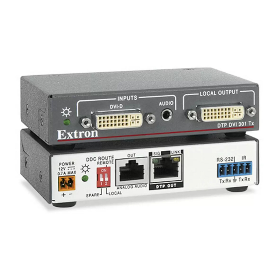
Page 11: Receiver Connections
This cable carries analog audio only and is not needed for applications that do not require this audio signal. DVI-D output connector — Connect a display with a DVI input to display the transmitted direct digital image. See “DVI connector pin assignments“ for pin assignments. DTP DVI 301 • Installation and Operation... - Page 12 2-pole connector or the power input connector on the transmitter (item “Power supply wiring“ to wire the connector. NOTE: One power supply can power both units. A power supply is included with the transmitter. DTP DVI 301 • Installation and Operation...
-
Page 13: Pin Assignments And Wiring
DDC data Ground (+5 V) TMDS clock+ CEC control* Hot Plug Detect TMDS clock– * CEC control on pin 8 is a proprietary usage, not the industry standard. Figure 5. DVI Connector DTP DVI 301 • Installation and Operation... -
Page 14: Tp Cable Termination
TIA/EIA T 568A or TIA/EIA T 568B. • Do not use Extron UTP23SF-4 Enhanced Skew-Free™ AV UTP cable or STP201 cable to link the transmitter and receiver. The DTP DVI 301 Tx/Rx does not work properly with these cables. •... - Page 15 Feed each individual wire into the appropriate slot of the RJ-45 connector and crimp the cable in the normal manner, folding the tangs at the end of the connector over the shielded tape (see figure 9). Crimped Connector Figure 9. Crimped RJ-45 Connector DTP DVI 301 • Installation and Operation...
-
Page 16: Power Supply Wiring
6 for details. NOTE: Do not tin the power supply leads before installing them in the connector. Tinned wires are not as secure in the connector and could be pulled out. DTP DVI 301 • Installation and Operation... -
Page 17: Operation
If the other devices are not turned on before the video source, the image may not appear. DTP DVI 301 • Installation and Operation... -
Page 18: Reference Information
Specifications NOTES • This product consists of a transmitter (DTP DVI 301 Tx) and a receiver (DTP DVI 301 Rx), sold separately, with twisted pair cables linking the transmitter and receiver. • *Appropriate DVI-D to HDMI cables or adapters are required for HDMI signal input/output Video Maximum data rate ...... -
Page 19: Audio Input
Operating: +32 to +122 °F (0 to +50 °C) / 10% to 90%, noncondensing Cooling .......... Convection, no vents Mounting Rack mount ......Yes, with optional 1U high rack shelf Furniture mount ...... Yes, with optional under-desk mounting kit Enclosure type ........ Metal DTP DVI 301 • Reference Information... - Page 20 **CE and FCC testing is conducted with STP (shielded twisted pair) cable. MTBF ..........30,000 hours Warranty ........3 years parts and labor NOTES • All nominal levels are at ±10%. • Specifications are subject to change without notice. DTP DVI 301 • Reference Information...
-
Page 21: Part Numbers And Accessories
60-1213-12 DTP DVI 301 Rx receiver 60-1213-13 Included Parts These items are included with each DTP DVI 301 transmitter and receiver: Included parts Part Number DTP DVI 301 Tx Transmitter 12 VDC, 1 A external power supply with 3.5 mm, 2-pole captive... -
Page 22: Mounting Accessories
CAUTION: Installation and service must be performed by authorized personnel only. The 1-inch high, quarter rack width DTP DVI 301 transmitter or receiver can be placed on a table, mounted in a rack, or mounted under a desk or table. The receiver can also be mounted on a projector bracket. -
Page 23: Extron Warranty
Extron Warranty Extron Electronics warrants this product against defects in materials and workmanship for a period of three years from the date of purchase. In the event of malfunction during the warranty period attributable directly to faulty workmanship and/or materials, Extron Electronics will, at its option, repair or replace said products or components, to whatever extent it shall deem necessary to restore said product to proper operating condition, provided that it is returned within the warranty period, with proof of purchase and description of malfunction to: USA, Canada, South America,...