Extron electronics DTP DVI 330 Setup Manual
Extron electronics dtp dvi 330 digital video extender setup guide
Hide thumbs
Also See for DTP DVI 330:
- User manual (20 pages) ,
- User manual (19 pages) ,
- Setup manual (2 pages)
Advertisement
Quick Links
Download this manual
See also:
User Manual
DTP DVI 330 • Setup Guide
This guide provides quick start instructions for an experienced installer to set up and operate the
Extron DTP DVI 330 digital video extender. The DTP DVI 330 transmitter and receiver pair can extend
a DVI signal up to 330 feet (100 m).
NOTE: For full installation and operation details, see the DTP DVI 330 User Guide, available at
www.extron.com).
Installation
Step 1 — Mounting
Turn off or disconnect all equipment power sources and mount the Tx and Rx units as required.
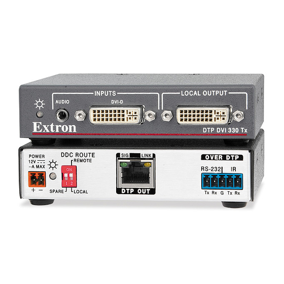
DTP DVI 330 Tx
INPUTS
DVI-D
AUDIO
Front
3
DTP DVI 330 Rx
Front
Step 2 — Connections
a
DVI Input connector (Tx) — Connect a DVI cable between this port and the DVI output port of the digital video source.
b
Local Output connector (Tx) — If desired, connect a DVI monitor for local monitoring of the input digital image.
c
Audio input (Tx) — Connect an unbalanced stereo audio source to this 3.5 mm mini stereo jack for an analog audio input.
d
RS-232 and IR connectors (both units) — To pass serial or infrared data or control
signals, such as serial control of a projector, connect the master device to the transmitter
and the slave device to the receiver via the RS-232 and IR captive screw connector on both
units.
e
DTP RJ-45 connectors (both units) — Connect transmitter DTP Out to receiver DTP In.
Extron recommends that you terminate both cable ends in accordance with the following
specifications, at a minimum:
TIA/EIA T 568 B
z
24 AWG, solid conductor
z
ATTENTION: Do not connect these devices to a computer data or telecommunications
network.
Sig(nal) LED (both units) — This LED lights when the unit is receiving a TMDS clock signal on the
DVI input (transmitter) or any valid signal on the DTP In connector (receiver).
Link LED (both units) — This LED lights when a valid link is established between the units on the
DTP cable.
f
DVI Output connector (Rx) — Connect a display with a DVI input for display of the transmitted direct digital image.
LOCAL OUTPUT
DTP DVI 330 Tx
1
2
OUTPUTS
AUDIO
L
R
DVI-D
DTP DVI 330 Rx
6
7
CAT 6A, shielded
z
DDC ROUTE
POWER
REMOTE
12V
0.8 A MAX
ON
1 2
SHARE
LOCAL
Rear
8
POWER
SIG
12V
0.8 A MAX
DTP IN
Rear
8
5
Tx/Rx
Pins
OVER DTP
SIG
LINK
RS-232
IR
DTP OUT
Tx
Rx
G
Tx
5
4
OVER DTP
LINK
RS-232
IR
Tx
Rx
G
Tx
4
Connected RS-232
and IR Device Pins
Transmit pin on connected unit
Receive pin on connected unit
Ground
Transmit pin on connected unit
Receive pin on connected unit
Pins:
TIA/EIA T
12345678
568 B
Pin
Wire color
1
White-orange
Orange
2
3
White-green
4
Blue
5
White-blue
Green
6
7
White-brown
8
Brown
TP Wires
Rx
Rx
Advertisement

Related Manuals for Extron electronics DTP DVI 330


Summary of Contents for Extron electronics DTP DVI 330
- Page 1 This guide provides quick start instructions for an experienced installer to set up and operate the Extron DTP DVI 330 digital video extender. The DTP DVI 330 transmitter and receiver pair can extend a DVI signal up to 330 feet (100 m).
- Page 2 +1.714.491.1500 +1.919.850.1000 +31.33.453.4040 +65.6383.4400 +91.80.3055.3777 +86.21.3760.1568 +1.714.491.1517 FAX +1.919.850.1001 FAX +31.33.453.4050 FAX +65.6383.4664 FAX +91.80.3055.3737 +86.21.3760.1566 FAX 68-2342-50 www.extron.com © Rev A 2012 Extron Electronics All rights reserved. All trademarks mentioned are the property of their respective owners. 12 12...