
Related Manuals for Pride Mobility JET1


Summary of Contents for Pride Mobility JET1
- Page 1 Owner’s Manual Stylish Design and Premium Performance ® Exeter, PA St. Catharines, ON 1-800-800-8586 www.pridemobility.com...
- Page 2 S A F E T Y G U I D E L I N E S Please read and follow all instructions in this owner’s manual before attempting to operate your power chair for the first time. If there is anything in this manual you do not understand, or if you require additional assistance for set-up, contact your authorized Pride provider.
-
Page 3: Table Of Contents
T A B L E C O N T E N T S INTRODUCTION......................... 4 SAFETY ............................6 III. EMI/RFI ............................14 IV. THE JET 1..........................16 ASSEMBLY..........................21 VI. COMFORT ADJUSTMENTS....................24 VII. DISASSEMBLY ......................... 28 VIII. OPERATION ..........................29 IX. -
Page 4: Introduction
I N T R O D U C T I O N INTRODUCTION Welcome to Pride Mobility Products Corporation (Pride). Congratulations on the purchase of your new Pride Power Chair. The Pride Power Chair design combines the most advanced state-of-the-art components with modern, attractive styling. - Page 5 I N T R O D U C T I O N Pride Owners Club As an owner of a Pride product, you are invited to register your product’s warranty and enroll in the Pride Owners Club. You may do so by filling out and returning your enclosed registration card or by visiting Pride’s web site at www.pridemobility.com.
-
Page 6: Safety
I I . S A F E T Y SAFETY WARNING! Do not operate your new power chair for the first time without completely reading and understanding this owner’s manual. Your power chair is a state-of-the-art life-enhancement device designed to increase mobility. Pride provides an extensive variety of products to best fit the individual needs of the power chair user. -
Page 7: Weight Limitations
I I . S A F E T Y n Check the brakes. See X. “Care and Maintenance.” n Check battery charge. See IX. “Batteries and Charging.” NOTE: If you discover a problem, contact your authorized Pride provider for assistance. Weight Limitations Your power chair is rated for a maximum weight capacity. - Page 8 I I . S A F E T Y WARNING! When climbing an incline, do not zigzag or drive at an angle up the face of the incline. Drive your power chair straight up the incline. This greatly reduces the possibility of a tip or a fall.
-
Page 9: Freewheel Mode
I I . S A F E T Y a paved area – especially at high speed while turning), and abrupt directional changes. High cornering speeds are not recommended. If you feel that you may tip over in a corner, reduce your speed and steering angle (i.e., lessen the sharpness of the turn) to prevent your power chair from tipping. -
Page 10: Public Streets And Roadways
I I . S A F E T Y Figure 1a. Curb Approach (Correct and Incorrect ) Public Streets and Roadways WARNING! You should not operate your power chair on public streets and roadways. Be aware that it may be difficult for traffic to see you when you are seated on your power chair. -
Page 11: Motor Vehicle Transport
I I . S A F E T Y EMI & RFI Laboratory tests performed by the Food and Drug Administration (FDA) have shown that radio waves can cause unintended motion of electric mobility vehicles. Radio waves are a form of electromagnetic energy (EM). When EM adversely affects the operation of an electronic device, it is called Electromagnetic Interference (EMI) or Radio Frequency Interference (RFI). -
Page 12: Reaching And Bending
I I . S A F E T Y WARNING! If you require a positioning belt to safely operate your power chair, make sure it is fastened securely. Serious personal injury may result if you fall from the power chair. WARNING! The positioning belt is not designed for use as a seat belt in a motor vehicle. -
Page 13: Removable Parts
I I . S A F E T Y Preventing Unintended Movement WARNING! If you anticipate being seated in a stationary position for an extended period of time, turn off the power. This will prevent unexpected motion from inadvertent joystick contact. This will also eliminate the possibility of unintended chair movement from electromagnetic (EM) sources. -
Page 14: Emi/Rfi
I I I . E M I / R F I Laboratory tests performed by the Food and Drug Administration (FDA) have shown that radio waves can cause unintended motion of Power chairs. Radio waves are a form of electromagnetic energy. When this energy ad- versely affects the operation of an electronic device, it is called Electromagnetic Interference (EMI) or Radio Frequency Interference (RFI). - Page 15 I I I . E M I - R F I Are all power chairs susceptible to EMI-RFI? Each make and model of chair differs in its ability to resist electromagnetic interference. That is, each has a particular level of “immunity” to interference, measured in volts per meter (Vm). A higher immunity level offers greater protection.
-
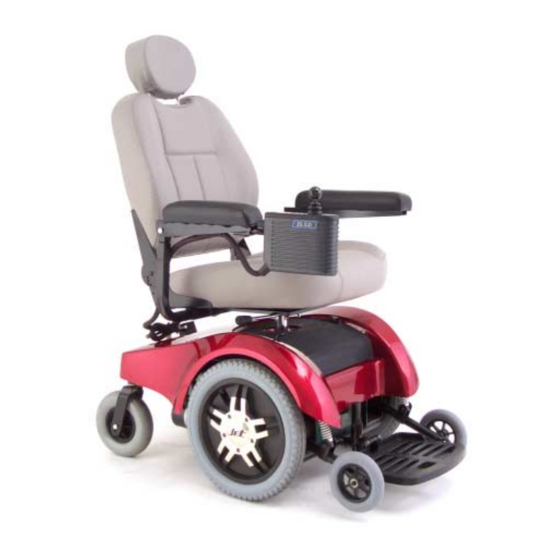
Page 16: The Jet 1
I V . T H E J E T Your Jet 1 has two main assemblies: the seat and the power base. See figures 2 and 3a. Typically, the seating assembly includes the armrests, seat-back, seat base, and a joystick controller. Your Jet 1 seat may also have some optional accessories attached to it, such as a basket, a cane/crutch holder, or a cup holder. - Page 17 I V . T H E J E T ARMREST ARMREST HEIGHT ADJUSTMENT KNOBS ARMREST WIDTH ADJUSTMENT SETSCREWS CONTROLLER HARNESSES Figure 3a. Rear View Figure 3b. Battery Charger Cord Jet 1/RevD/Jul03 www.pridemobility.com...
- Page 18 I V . T H E J E T Specifications Suspension: Drive Wheels: 14 in., pneumatic, center mounted (solid tires are optional) Rear Casters: 8 in., solid, rear articulating Anti-tip: 6 in., solid, front mounted Max. Speed: 4.5 mph Brakes: “Intelligent Braking,”...
- Page 19 I V . T H E J E T UTILITY TRAY The utility tray is located on the rear of your Jet 1. The utility tray is exposed through the body shroud. The utility tray consists of the battery charger cord, the ammeter, the main circuit breaker, the controller harness connectors and the power seat connector.
-
Page 20: Freewheel Levers
I V . T H E J E T FREEWHEEL LEVERS For your convenience, your Jet 1 is equipped with two freewheel levers. See figures 5 and 6. These levers allow you to disengage the drive motors and maneuver the chair manually. WARNING! Do not use your Jet 1 while the drive motors are disengaged unless you are in the presence of an attendant! Do not disengage the drive motors when your Jet 1 is on an incline. -
Page 21: Assembly
A S S E M B L Y To reduce the possibility of shipping damage, your Jet 1’s seat is removed from the power base, and the seat back is removed from the seat assembly before your Jet 1 is shipped. The joystick may also have been removed from the armrest. -
Page 22: Seat Installation
A S S E M B L Y SEAT INSTALLATION WARNING! Do not pick up the seat frame by the armrests. They are free to pivot, and you may lose control of the seat if they do so, resulting in personal injury and/or damage to the chair. - Page 23 A S S E M B L Y Figure 11. Charger Inhibit Connector Figure 12. Dynamic Joystick Controller SLIDE JOYSTICK INTO BRACKET SETSCREW Figure 13. Joystick And Bracket Jet 1/RevD/Jul03 www.pridemobility.com...
-
Page 24: Comfort Adjustments
V I . C O M F O R T A D J U S T M E N T S After you have become familiar with your Jet 1’s NUT AND BOLT operation, you may find the need to adjust the seat. -
Page 25: Armrest Angle Adjustment
V I . C O M F O R T A D J U S T M E N T S ARMREST ANGLE ADJUSTMENT You can adjust the armrest angle to fit your spe- cific needs. See figure 16. TURN THIS SCREW TO To change the armrest angle: CHANGE... - Page 26 V I . C O M F O R T A D J U S T M E N T S FOOTREST HEIGHT The footrest height is easily adjusted to one of six different heights in one inch increments. To raise or lower the footrest: 1.
- Page 27 V I . C O M F O R T A D J U S T M E N T S 3. Slide the leg rest in or out to the desired length. 4. Tighten the bolt and reinstall the two screws on each leg rest extension.
-
Page 28: Disassembly
V I I . D I S A S S E M B L Y SEAT REMOVAL You may wish to remove the seat for transportation. See figure 24. To remove the seat: 1. Turn the power off. 2. Make sure your Jet 1 is not in freewheel mode. 3. -
Page 29: Operation
V I I I . O P E R A T I O N You control the speed and direction of your Jet 1 with the joystick controller. NOTE: In an emergency situation, use the on/off button to stop the Jet 1. To operate your Jet 1: 1. - Page 30 V I I I . O P E R A T I O N The controller is designed to maximize user safety under normal operating conditions. This controller, however, cannot take into account circumstances that put your Jet 1 outside of its normal operating environment as de- scribed within this manual.
- Page 31 V I I I . O P E R A T I O N BATTERY CONDITION METER The battery condition meter is located immediately behind the joystick. This enables you to monitor battery life. The battery condition meter indicates the approximate amount of battery life left. See figure 25. n Red, yellow, and green circles indicate that the batteries are fully charged.
-
Page 32: Sleep Mode
V I I I . O P E R A T I O N SLEEP MODE The Dynamic controller does not use a sleep mode, since it operates at a low power state when not in use. THERMAL ROLLBACK Jet 1 controllers are equipped with a thermal rollback circuit. This circuit monitors the temperature of the motors and the controller. -
Page 33: Batteries And Charging
I X . B A T T E R I E S A N D C H A R G I N G BATTERIES Your Jet 1 uses two long-lasting, 12-volt batteries. These batteries are sealed, maintenance free, deep-cycle batteries. Since they are sealed, there is no need to check the electrolyte (fluid) level. Deep-cycle batteries are designed to handle a longer and deeper discharge. - Page 34 I X . B A T T E R I E S A N D C H A R G I N G 3. Remove the battery charger cord from the back pouch of your Jet 1 and plug it into the battery charger power outlet located on the utility tray.
- Page 35 I X . B A T T E R I E S A N D C H A R G I N G BATTERIES AND CHARGING—FREQUENTLY ASKED QUESTIONS (FAQS) How does the charger work? The battery charger takes the standard wall outlet voltage of 120 VAC (alternating current) and converts it to 24 VDC (direct current).
- Page 36 I X . B A T T E R I E S A N D C H A R G I N G What type of battery should I use? We recommend deep-cycle batteries that are sealed and maintenance free. Both AGM and Gel-Cell are deep- cycle batteries that are similar in performance.
- Page 37 I X . B A T T E R I E S A N D C H A R G I N G How should I store my Jet 1 and its batteries? If you do not use your Jet 1 regularly, we recommend maintaining battery vitality by charging the batteries at least once per week.
-
Page 38: Care And Maintenance
C A R E A N D M A I N T E N A N C E ROUTINE MAINTENANCE Your Jet 1 is a sophisticated power chair. Like any motorized vehicle, it requires routine maintenance checks. You can perform some of these checks, but others require assistance from your authorized Pride provider. Preventive maintenance is very important. -
Page 39: Daily Checks
C A R E A N D M A I N T E N A N C E WARNING! Do not use a high pressure hose to inflate your tires. n Use a rubber conditioner on the tire sidewalls to help pre- serve them. -
Page 40: Cleaning Instructions
C A R E A N D M A I N T E N A N C E 3. Slowly push the joystick forward until you hear the electric brakes click. Immediately release the joystick. You must be able to hear each electrical brake operating within a few seconds of joystick movement. Repeat this test three times, pushing the joystick backwards, then left, and then right. -
Page 41: Battery Replacement
C A R E A N D M A I N T E N A N C E Follow these easy steps for a quick and safe repair: 1. Completely deflate the tire if pneumatic. 2. Remove the cap in the center of the wheel that covers the drive wheel nut. See figure 30. 3. - Page 42 C A R E A N D M A I N T E N A N C E 13. Connect one circuit breaker harness to the empty positive terminal of one battery, and connect the other circuit breaker harness to the empty negative terminal of the other battery. WARNING! Make sure you tighten the fasteners so that the connections are secure.
-
Page 43: Corrective Maintenance
C A R E A N D M A I N T E N A N C E CORRECTIVE MAINTENANCE If the battery indicator gauge does not light up when you turn on the power: n Check the harness connections. Make sure they are tight. n Check the circuit breaker. -
Page 44: Optional Accessories
X I . O P T I O N A L A C C E S S O R I E S The following accessories are available from your authorized Pride provider. OXYGEN TANK HOLDER The removable oxygen tank holder is mounted to the back of the seat by means of the accessory bracket. CANE AND CRUTCH HOLDER The removable cane and crutch holder is mounted to the back of the seat by means of the accessory bracket. -
Page 45: Warranty
X I I . W A R R A N T Y FIVE YEAR LIMITED FRAME WARRANTY There will be a five year limited frame warranty on Pride Mobility Products Corporation workmanship. ONE YEAR LIMITED WARRANTY For one year from the date of purchase, Pride Mobility Products Corporation will repair or replace at our option to the original purchaser free of charge, any of the following parts found upon examination by an authorized representative of Pride Mobility Products Corporation to be defective in material and/or workmanship: n Electronic controllers and joystick assemblies... - Page 46 X I I . W A R R A N T Y WARRANTY EXCLUSIONS n ABS plastic body shrouds and footrest covers are wear items and not warranted. n Batteries (battery manufacturer provides a six month limited warranty) n Tires and tubes n Upholstery and seating n Repairs and/or modifications made to any part without specific prior written consent from Pride Mobility Products Corporation...
- Page 47 N O T E S...
- Page 48 Quality Control - Model Jet 1 Thank you for making the Jet 1 ATS your choice in power chairs. We have thoroughly inspected your Jet 1 ATS. The following checkmarks indicate that it has been driven and inspected. Controller Model #______________ Controller Serial # Serial #______________ Inclusion of all Parts...