Table of Contents
Advertisement
Quick Links
Advertisement
Table of Contents

Related Manuals for Extron electronics RGB 302


Summary of Contents for Extron electronics RGB 302
- Page 1 User’s Manual RGB 302/304 Universal Digital Interface...
-
Page 2: Table Of Contents
Contents Chapter One • Introduction to the RGB 302/304 RGB 302/304 Features ............1-1 SmartSave™ ............1-2 LCD Menu Driven Controls ........1-2 Memory Blocks and Memory Cycling ...... 1-2 Level Control (picture) ..........1-2 Peaking Control (sharpness) ........1-3 Horizontal Shift Control (centering) ...... - Page 3 Host-to-RGB 302/304 Instructions ........A-2 Simple Commands ..............A-3 Error Codes ................A-4 RGB 302/304-Initiated Messages .......... A-5 RGB 302/304 User’s Manual 68-354-01 First Edition 89-03 Written and printed in the USA Page ii Extron RGB 302/304 Universal Interface • User’s Manual...
- Page 4 ___ A Note, a Hint, or a Tip that may be helpful. ____ Possible Electrostatic Discharge (ESD) damage could result from touching electronic components. _____ Indicates word definitions. Additional information may be referenced in another section, or in another document. Extron RGB 302/304 Universal Interface • User’s Manual Page iii...
- Page 5 Notes ____ Extron RGB 302/304 Universal Interface • User’s Manual Page iv...
- Page 6 Chapter One Introduction to the RGB 302/304 SmartSave™ LCD Menu Driven Controls Memory Blocks and Memory Cycling Image Display Controls Automatic Sync Output Detection Keyboard Lockout RS-232 Control Interface Front Panel Controls Specifications Extron RGB 302/304 Universal Interface • User’s Manual...
-
Page 7: Chapter One • Introduction To The Rgb 302/304
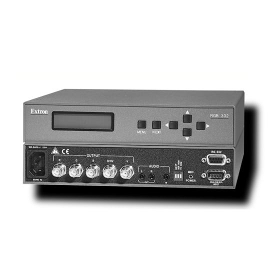
DIP switches. The RGB 304 is identical in performance and features as the RGB 302 with the exception being that, unlike the RGB 302, the RGB 304 has its 9-pin Analog/ECL input, Audio input, and MBC power jack located on the front panel of the unit, as shown below. -
Page 8: Smartsave
LCD Menu Driven Controls The RGB 302/304 does not have front panel “knobs” or “switches” to control its operation. Instead, the “controls” are displayed and adjusted using the Front Panel LCD display and the six front panel buttons. -
Page 9: Peaking Control (Sharpness)
“hot keys”. This feature disables front panel operation after setup. Auto-switching Power Supply The RGB 302/304 is equipped with an internal auto- switching power supply that operates from any input voltage in the 100 to 240 VAC, 50/60 Hz range. No equipment changes are necessary. -
Page 10: Dip Switch Settings
1. Use the Windows® RGB 302/304 Control Panel software provided by Extron (see next section). 2. The user may write software to control the RGB 302/ 304 from a PC or control system. See the Programmer’s Guide in Appendix A. -
Page 11: Front Panel Controls
INPUT The LCD panel cycles through 3 default menus when the RGB 302/304 is first powered on. Refer to Chapter 3 for instructions on using the RGB 302/304 menus. ___ There is a built-in time-out function which will return to the default menu cycle if no buttons are pressed for approximately 8 seconds. -
Page 12: Rgb 302/304 Specifications
Chapter 1 • Introduction to the RGB 302/304 RGB 302/304 Specifications Part Number .. 60-243-01 (RGB 302) .. 60-244-01 (RGB 304) User’s Manual .. 68-354-01 Dimensions .. 8.75" W x 9.5" D x 1.75" H Shipping Weight .. 5 lbs Input Power .. - Page 13 Chapter 1 • Introduction to the RGB 302/304 ____ Page 1-7 Extron RGB 302/304 Universal Interface • User’s Manual...
-
Page 14: Chapter Two Installing The Rgb 302/304
RGB 302/304 Universal Digital Interface User’s manual Chapter Two Installing the RGB 302/304 Easy Setup Procedure DIP Switch Settings Audio Connections Installation Check Memory Cycling Feature RS-232 Specifications Extron RGB 302/304 Universal Interface • User’s Manual... - Page 15 RS-232 50/60 Hz ____ The diagrams above show the front and rear panels of the RGB 302 (top pair) and RGB 304 (bottom pair). Easy Setup Procedure These easy-to-follow steps describe the general setup of the RGB 302/304. Refer to the example Application Diagrams at the end of this chapter.
- Page 16 6a. Turn power On at the data monitor/projector. 6b. Connect power to the RGB 302/304. 7. Observe that the RGB 302/304 LCD display lights up and cycles through the three default menus (below). 7a. The ID or Title Menu - Displays the name of the unit.
-
Page 17: Rear Panel Dip Switch Settings
The user supplies the audio cables. RGB 302 On the RGB 302, the audio input and output are both AUDIO located on the rear panel, as shown in the diagram to the left. -
Page 18: Installation Check
The scan rate menu may be used for troubleshooting as follows: • The timing for the RGB 302/304 is derived from the vertical sync signal. If the vertical sync signal is not present, both the vertical and horizontal frequencies will be zeroes, even if there is a horizontal signal present. -
Page 19: Memory Cycling Feature
Chapter 2 • Installing the RGB 302/304 Memory Cycling Feature The RGB 302/304 is preset at the factory with fifteen video formats which are stored in memory blocks. These memory blocks contain video formats which will match most computers. There are also 25 additional empty memory blocks which are user- defined. -
Page 20: Preset Memory Blocks
Sun2 81.0 63.9 Power Supply The RGB 302/304 is equipped with an internal auto- switching power supply that operates from any input voltage in the 100 to 240 VAC, 50/60 Hz range. No equipment changes are necessary. RS-232 Interface Specifications 9600 baud, no parity, 8 data bits and 1 stop bit. -
Page 21: Application Diagrams
50 /6 Control Cable Rear Front BNC 4 or 5 HR Cable MBC Cable Output Audio Local Monitor Large-Screen Data Monitor Data Projector Power PC, Macintosh Audio Amplifier or WorkStation Page 2-7 Extron RGB 302/304 Universal Interface • User’s Manual... -
Page 22: Chapter Three • Front Panel Menus
RGB 302/304 Universal Digital Interface User’s manual Chapter Three Front Panel Menus Menu Flowchart Default Cycle Menus Image Controls Menus Sync Controls Menus Option Controls Menus Default Settings Extron RGB 302/304 Universal Interface • User’s Manual... -
Page 23: Rgb 302/304 Menu Sequence
Default Cycle Menus MENU Press NEXT (or time-out) to return to the Default Cycle Menus EXIT MENU or Press MENU to return to the Image Controls Menus NEXT MENU Page 3-1 Extron RGB 302/304 Universal Interface • User’s Manual... -
Page 24: Using The Menu System
____ When using the front panel, a pause (time-out) of approximately 8 seconds will release the current menu mode and the RGB 302/304 returns to the 3-menu default cycle and saves any changes. If the user powers off the RGB 302/304 before returning to the default cycle (either by a time-out or Exit Menu), any new changes will not be saved. -
Page 25: Default Cycle Menus
The image controls menus, one of the four classes of menus, sets image shifting, level and peaking. When the RGB 302/304 is first powered up, the LCD displays three default menus for about 2 seconds each. From this default menu cycle, you can advance to the next class of menus, “Image Controls”, by... -
Page 26: Default Cycle Hot Keys
____ Using these “hot keys” to exit from the default menu cycle will only work if DIP Switch 1, located on the rear panel of the RGB 302/304, has been set Off. Setting it to Off means the Digital Display Sync Processing is not active, but Normal sync processing is active. -
Page 27: Keyboard Lock/Unlock Menu
____ Once the keyboard is locked it will remain locked even when power to the RGB 302/304 is removed. To alert the user upon power up if the keyboard has been locked, the unit will show the locked message. -
Page 28: Image Controls Menus
Image Controls Menus From the Default Cycle menus, press MENU to advance to the Image Controls menus. The image which the RGB 302/304 displays on a monitor or projector screen can be adjusted through these menus. Press to go to the... -
Page 29: Level Control Menu
NEXT Image Controls menus, or press MENU advance to the Sync Controls menus, or allow the time-out to occur to save any changes. Page 3-7 Extron RGB 302/304 Universal Interface • User’s Manual... -
Page 30: Sync Controls Menus
. After selecting a new sync setting, NEXT allow the time-out to occur to save it. ____ Automatic Sync means the RGB 302/304 detects which terminated* output connectors are currently active and will set the output sync as either Sync on Green, Composite Sync, or Separate H &... -
Page 31: Horizontal Polarity Menu
Press to return to the Sync Controls NEXT menus, or press to advance to the MENU Option Controls menus, or allow the time-out to occur to save any changes. Page 3-9 Extron RGB 302/304 Universal Interface • User’s Manual... -
Page 32: Option Controls Menus
Chapter 3 • Front Panel Menus Option Controls Menus Among the menu options for the RGB 302/304 are the LCD Backlite, Memory Cycling, and System Reset. Press to go to the Backlite menu, or NEXT press to advance to the Exit Menu, or MENU allow the time-out to occur. -
Page 33: Confirm Reset Menu
Default Settings on Power Up On power up, the RGB 302/304 will default to the last settings which were current just prior to the power off. All 25 user-defined memory blocks will be saved if Memory Cycling had been set On. - Page 34 RGB 302/304 Universal Digital Interface User’s manual Chapter Four Using the Windows® Control Program Installing the Windows® Control Software Normal Windows Control Panel RGB 302/304 Help Extron RGB 302/304 Universal Interface • User’s Manual...
-
Page 35: Installing Windows® Control Software
RGB 302/304 (see diagrams below). 1. Connect the PC’s Comm port to the RS-232 connector on the back of the RGB 302/304. 2. Power up the RGB 302/304, the PC, and load Windows. 3. To install the software from the 3.5” floppy disk onto the hard disk, run SETUP.EXE from the floppy disk. -
Page 36: Normal Windows Control Panel
The Window in the above illustration shows an Extron Program Group. 5. Double-click on the RGB 302/304 Control Program icon to start the program. You will be asked to select the Comm Port. After selecting the Comm Port, the software looks for the RGB 302/304, “reads”... -
Page 37: Rgb 302/304 Help
Chapter 4 • Using the Windows® Control Program RGB 302/304 Help Double-click on the RGB 302 + 304 Help Icon (or press F1 at any time) to open the Help Window. An example of what this might look like is shown below. -
Page 38: Appendix A Programmer's Guide
RGB 302/304 Universal Digital Interface User’s manual Appendix A Programmer’s Guide Remote Control Port – RS-232 Host-to-RGB 302/304 Instructions Command/Response Table RGB 302/304-Initiated Messages Extron RGB 302/304 Universal Interface • User’s Manual... -
Page 39: Remote Control Port (Rs-232
— No connection Commands and responses for programming the RGB 302/304 Interface from a Host system connected to the RS-232 port are listed on the next page. The RS-232 protocol is 9600 baud, 8-bit, 1 stop bit and no parity. -
Page 40: Host-To-Rgb 302/304 Instructions
Automatic (0), then 0 = RGB with sync on Green, 8 = RGB with separate H & V, and 9 = RGB with Composite sync. = 0 or 1, 0 = Off, 1 = On Extron RGB 302/304 Universal Interface • User’s Manual Page A-2... -
Page 41: Simple Commands
02 (up to 32 characters) Menu Language English 23 + 31 Fnc 1 Spanish 23 + 32 Fnc 2 French 23 + 33 Fnc 3 German 23 + 34 Fnc 4 Page A-3 Extron RGB 302/304 Universal Interface • User’s Manual... -
Page 42: Error Codes
Error Codes Code Description Invalid command Invalid value (too large) Illegal command for this configuration (DIP Switch 1 is set ON for Digital Display Sync Processing and Horizontal/Vertical Shift is requested) Extron RGB 302/304 Universal Interface • User’s Manual Page A-4... -
Page 43: Rgb 302/304-Initiated Messages
Appendix A • Programmer’s Guide RGB 302/304-Initiated Messages When a local event takes place, such as a Front Panel operation, the RGB 302/304 responds by sending a message to the Host. These RGB 302/304-initiated messages are listed below. As an example, the RGB... - Page 44 Appendix A • Programmer’s Guide ____ Extron RGB 302/304 Universal Interface • User’s Manual Page A-6...