
Related Manuals for Extron electronics RGB 160


Summary of Contents for Extron electronics RGB 160
- Page 1 User’s Manual RGB 160 and RGB 164xi Universal Interfaces 68-549-01 Rev. D 10 07...
- Page 2 Safety Instructions • English Warning Power sources • This equipment should be operated only from the power source This symbol is intended to alert the user of important indicated on the product. This equipment is intended to be used with a main power operating and maintenance (servicing) instructions in system with a grounded (neutral) conductor.
-
Page 3: Table Of Contents
This page is intentionally left blank Table of Contents Chapter 1 • Introduction ... 1-1 About this Manual ... 1-2 About the Interfaces ... 1-2 Features ... 1-2 Chapter 2 • Controls and Installation Front Panel Features ... 2-2 Rear Panel Features ... -
Page 4: Chapter 1 • Introduction
Table of Contents, cont’d RGB 160xi and RGB 164xi This page is intentionally left blank Chapter One Introduction About this Manual About the Interfaces Features RGB 160xi and RGB 164xi • Table of Contents... -
Page 5: About The Interfaces
Introduction About this Manual This manual documents two universal interfaces: RGB 160xi and RGB 164xi. Unless otherwise specified, any references to “the interface” refers to the features or operation of both interfaces. About the Interfaces The RGB 160xi and 164xi are universal interfaces with a video bandwidth of 300 MHz and a horizontal frequency range of 15-160 kHz. -
Page 6: Chapter 2 • Controls And Installation
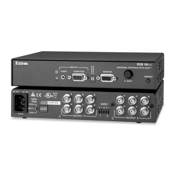
DDSP disables horizontal shift. Min/max LED — Lights red whenever the lower or upper limits of the horizontal shift control is reached. RGB 160xi and RGB 164xi • Controls and Installation RGB 160 UNIVERSAL INTERFACE W/ADSP MIN/MAX H. SHIFT RGB 164xi UNIVERSAL INTERFACE WITH ADSP™... -
Page 7: Installation
Controls and Installation, cont’d Installation Installation overview Except where noted, the installation procedures for the various interface models are the same. See "Cabling" in this chapter for additional information. If desired, mount the interface to an equipment rack (RGB 164xi only) or to or through a desk or other suitable surface using Extron’s optional mounting kit. -
Page 8: Under Desk Mounting
Controls and Installation, cont’d Under desk mounting Mount the interface under a desk or in a podium, using an optional Extron MBU 125 Under-desk mount kit (part #70-077-01) as follows: Attach the mounting brackets to the interface using four machine screws supplied with the mounting kit (figure 2-6). -
Page 9: Cabling
Controls and Installation, cont’d Cabling Figure 2-9 and figure 2-10 show how to connect the interfaces. Front D IO IN PU IV ER L IN R FA B 15 0 xi /A D IF T M IN /M A 40 V 10 0-2 V 50 V 10... -
Page 10: Setting The Dip Switches
Controls and Installation, cont’d Before connecting audio, determine whether your audio system is unbalanced or balanced. Connect an audio device, such as powered speakers, to the rear panel stereo audio output connector for balanced or unbalanced audio output. Following the wiring guide (figure 2-13), insert the wires into the appropriate openings in the captive screw connector. -
Page 11: Setting Internal Jumpers
Controls and Installation, cont’d Setting internal jumpers The jumpers inside the interfaces are set at the factory for optimal use by most systems. However, you can change a jumper setting to meet the needs of a particular system. Changes to internal jumper settings must be performed by authorized service personnel only. The user-configurable, internal jumpers control the following functions: •... - Page 12 Controls and Installation, cont’d The jumpers perform the following functions: J20: Sync polarity jumper — This jumper adjusts the output sync polarity. Horizontal (H) and vertical (V) sync output can either follow input sync polarity, or be forced to negative. •...
-
Page 13: Appendix A • Reference Information
Reference Information Specifications Video Gain ... Unity, (0.725 Vp-p) 50% peaking, (0.75 Vp-p) 100% peaking Bandwidth ... 300 MHz (-3 dB) Video input Number/signal type ... 1 analog RGBHV, RGBS, RGsB, RsGsBs Connectors ... 1 female 15-pin HD Nominal level ... 0.7 Vp-p for RGB Minimum/maximum levels ... -
Page 14: Accessories And Part Numbers
Reference Information, cont’d Temperature/humidity ... Storage: -40 to +158 °F (-40 to +70 °C) / 10% to 90%, noncondensing Operating: +32 to +104 °F (0 to +40 °C) / 10% to 90%, noncondensing Rack mount RGB 160xi ... No RGB 164xi ... Yes, with optional rack shelf, #60-190-01 Furniture mount ... -
Page 15: Mounting Templates
Reference Information, cont’d Mounting Templates All dimensions are in inches. Drawings not to scale. 6.95 6.39 1.79” x 6.39” OPENING IN DESK (Requires mounting kit P/N 70-077-02) Through desk mounting template Recommended pilot drill hole size for supplied screws = 3/32” x 1/4” deep RGB 160xi FRONT Mounting Bracket Templates Figure A-1 —... - Page 16 Extron’s Warranty Extron Electronics warrants this product against defects in materials and workmanship for a period of three years from the date of purchase. In the event of malfunction during the warranty period attributable directly to faulty workmanship and/or materials, Extron Electronics will, at its option, repair or replace said products or components, to whatever extent it shall deem necessary to restore said product to proper operating condition, provided that it is returned within the warranty period, with proof of...
- Page 17 Extron Electronics, USA Extron Electronics, Europe Extron Electronics, Asia 1230 South Lewis Street Beeldschermweg 6C 135 Joo Seng Rd. #04-01 Anaheim, CA 92805 3821 AH Amersfoort, The Netherlands PM Industrial Bldg., Singapore 368363 800.633.9876 714.491.1500 +800.3987.6673 +31.33.453.4040 +800.7339.8766 +65.6383.4400 FAX 714.491.1517 FAX +31.33.453.4050 FAX +65.6383.4664 www.extron.com...