Table of Contents
Advertisement
Quick Links
Download this manual
See also:
Setup Manual
Extron Electronics, USA
Extron Electronics, Europe
1230 South Lewis Street
Beeldschermweg 6C
Anaheim, CA 92805
3821 AH Amersfoort
USA
The Netherlands
714.491.1500
+31.33.453.4040
www.extron.com
Fax 714.491.1517
Fax +31.33.453.4050
© 2002 Extron Electronics. All rights reserved.
Extron Electronics, Asia
Extron Electronics, Japan
135 Joo Seng Road, #04-01
Daisan DMJ Building 6F
PM Industrial Building
3-9-1 Kudan Minami
Singapore 368363
Chiyoda-ku, Tokyo 102-0074 Japan
+65.6383.4400
+81.3.3511.7655
Fax +65.6383.4664
Fax +81.3.3511.7656
User's Manual
RGB 130 xi xi xi xi xi , 134 xi xi xi xi xi , 160 xi xi xi xi xi , 164 xi xi xi xi xi
Universal Interfaces
68-549-01
Printed in the USA
Advertisement
Table of Contents

Related Manuals for Extron electronics RGB 160xi


Summary of Contents for Extron electronics RGB 160xi
- Page 1 Extron Electronics, USA Extron Electronics, Europe Extron Electronics, Asia 1230 South Lewis Street Beeldschermweg 6C 135 Joo Seng Road, #04-01 Anaheim, CA 92805 3821 AH Amersfoort PM Industrial Building Singapore 368363 The Netherlands 714.491.1500 +31.33.453.4040 +65.6383.4400 www.extron.com Fax 714.491.1517 Fax +31.33.453.4050 Fax +65.6383.4664 ©...
-
Page 2: Fcc Class A Notice
Precautions Safety Instructions • English Warning This symbol is intended to alert the user of important Power sources • This equipment should be operated only from the power source indicated on the product. This equipment is intended to be used with a main operating and maintenance (servicing) instructions power system with a grounded (neutral) conductor. -
Page 3: Table Of Contents
Under desk mounting ... 2-6 Through desk mounting ... 2-7 Cabling ... 2-8 Setting the DIP switches ... 2-11 All models ... 2-11 RGB 160xi and RGB 164xi only ... 2-11 Setting internal jumpers ... 2-12 Appendix A • Specifications Part Numbers, and Templates ... -
Page 4: Chapter 1 • Introduction
Table of Contents, cont’d RGB 130xi xi xi xi xi, 134xi xi xi xi xi, 160xi xi xi xi xi, 164xi xi xi xi xi Page intentionally left blank Chapter One Introduction About this Manual About the Interfaces Features RGB 130xi xi xi xi xi, 134xi xi xi xi xi, 160xi xi xi xi xi, 164xi xi xi xi xi • Table of Contents... -
Page 5: About This Manual
Introduction About this Manual This manual documents four universal interfaces: RGB 130xi, RGB 134xi, RGB 160xi, and RGB 164xi. Unless otherwise specified, any references to “the interface” shall refer to the features or operation of all four interfaces. About the Interfaces... -
Page 6: Front Panel Features
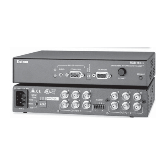
RGB 164xi UNIVERSAL INTERFACE WITH ADSP™ MIN/MAX H. SHIFT RGB 160xi and RGB 164xi — HD 15-pin female analog video input connector. MBC power (RGB 130xi and RGB 134xi only) — 2.5 mm jack provides power for MBC buffer. ID bit termination DIP switches (RGB 160xi and RGB 164xi only) —... -
Page 7: Installation
DIP switches — 4 switches to control sync on green on output, Digital Display Sync Processing, serration pulses, and either 75- Ohm (RGB 130xi and RGB 134xi) or spare (RGB 160xi and RGB 164xi) (see Setting the DIP switches in this chapter). -
Page 8: Under Desk Mounting
Controls and Installation, cont’d False Front Panel uses 2 front holes D IO IN PU IV ER L IN R FA B 16 4 xi /A D IF T Use 2 Mounting Holes on Opposite Corners Figure 2-9 — Rack mounting the RGB 164xi Install a blank panel (included in the rack kit) or another 1U half-rack unit on the unused side of the rack. -
Page 9: Cabling
SUN or SGI Computer Figure 2-12 — RGB 130xi installation Connect the computer to the interface’s Analog/ECL (RGB 130xi and RGB 134xi) or Analog connector (RGB 160xi and RGB 164xi). Extron does not guarantee the performance of the interface if a low quality input cable is used. -
Page 10: Setting The Dip Switches
Setting the DIP switches DIP switches on the rear panel of the RGB 130xi, and RGB 134xi, and on the front and rear panels of the RGB 160xi and RGB 164xi, are used to configure the interface. The switches can be either the rocking type or the sliding type. -
Page 11: Rgb 160Xi And Rgb 164Xi Only
ID PIN 4 & ID PIN 11 On — Set both pins to On if you are using the RGB 160xi or RGB 164xi interface with a laptop computer that is not connected to a local monitor. -
Page 12: Appendix A • Specifications
Controls and Installation, cont’d Pin 1 to Pin 2 Pin 2 to Pin 3 Rear J20: Sync polarity jumper J40: Vertical sync width jumper Power Supply Front Figure 2-19 — Circuit board jumper locations Figure 2-20 — Changing jumper settings J40: Vertical sync width jumper —... -
Page 13: Specifications
Vertical frequency ... Autoscan 30 Hz to 120 Hz Return loss ... -30dB @ 5 MHz Maximum DC offset ... 4.0V Video output Number/signal type ... RGB 130xi, RGB 160xi ... 1 analog RGBHV, RGBS, RGsB RGB 134xi, RGB 164xi ... 2 analog RGBHV, RGBS, RGsB Connectors ... -
Page 14: Accessories And Part Numbers
#70-077-02 Enclosure type ... Metal Enclosure dimensions RGB 130xi, RGB 160xi, ... 1.75" H x 6.4" W x 6.0" D 4.4 cm H x 16.3 cm W x 15.2 cm D (Depth excludes connectors.) RGB 134xi, RGB 164xi ... 1.75" H x 8.75" W x 6.0" D 4.4 cm H x 22.2 cm W x 15.2 cm D... -
Page 15: Mounting Templates
Specifications, Part Numbers, Templates, cont’d Signal input cable kits for RGB 160xi, RGB 164xi VGA M6’ MHR VGA M3’ MHRA VGA M6’ MHRA VGA M12’ MHRA Mac Adapter kit with Audio 13W3 Adapter cable kit with Audio BNC cables BNC-5 3’ HR BNC-5 6’... - Page 16 Specifications, Part Numbers, Templates, cont’d RGB 130xi xi xi xi xi, 134xi xi xi xi xi, 160xi xi xi xi xi, 164xi xi xi xi xi • Specifications, Part Numbers, and Templates RGB 134 xi and RGB 164 xi Under-Desk Mounting Bracket Dimensions RGB 130xi xi xi xi xi, 134xi xi xi xi xi, 160x x x x x i, 164x x x x x i •...
- Page 17 Specifications, Part Numbers, Templates, cont’d A-10 RGB 130xi xi xi xi xi, 134xi xi xi xi xi, 160xi xi xi xi xi, 164xi xi xi xi xi • Specifications, Part Numbers, and Templates RGB 134 RGB 164 Through Desk Mounting Bracket Dimensions...