Extron electronics RGB 192 User Manual
Computer-video interface
Hide thumbs
Also See for RGB 192:
- User manual (16 pages) ,
- Specifications (3 pages) ,
- User manual (15 pages)
Advertisement
Quick Links
RGB 192V Computer-Video Interface • User Guide
About this Manual
This manual contains operation and configuration instruction for the Extron RGB 192, a universal interface.
About the RGB 192
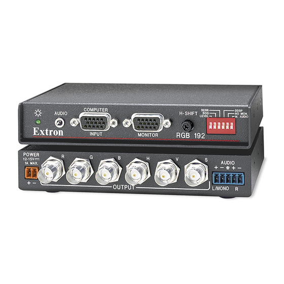
The RGB 192 is an analog computer-video interface with 300 MHz (-3 dB) video bandwidth and Digital Display Sync
Processing (DDSP™). Figure 1 shows a typical RGB 192 application. The interface accepts a computer video and an
unbalanced computer stereo audio input. It features a local monitor output and an RGBHV, RGBS or RGsB output. The
RGB 192 features horizontal centering and level boost. It also features a balanced, line level stereo or mono audio output.
Extron
RGB 192V
AU
DI O
C O
M P
Interface
U T
E R
M O
N IT
O R
H -S
R G
Shown with included
under-desk mounting
brackets.
Local
Monitor
PC
Figure 1.
Typical RGB 192 Application
The RGB 192 allows for furniture and under-desk mounting. It has an external switching power supply for worldwide
power compatibility.
Features
Flexible mounting options — The interface can be mounted under a desk or podium, mounted on a rack, or
•
through a desk with optional mounting kits.
Stereo audio — The interface outputs unbalanced PC stereo audio as line level, balanced stereo (or, depending on
•
a DIP switch position, mono).
Level (boost) control — A front panel control compensates for signal losses from long cable runs.
•
Horizontal centering control — A front panel control allows a horizontal centering adjustment.
•
Sync processing — Using regular sync processing to allow centering control (H-shift) can create problems with
•
some digital display devices as a result of the sync delay. The Extron DDSP, ensures proper displays without altering
sync pulse timing or width. The sync processing type is selected via the front panel DIP switches.
RGBHV, RGBS, or RGsB outputs — Select the output format via cabling setup and front panel DIP switch.
•
Serration pulse switch — This DIP switch-selectable feature adds or strips the serration pulses from the output
•
signal to make it compatible with digital display devices. Use the serration pulse switch if flagging or bending occurs
at the top of the video display.
H IF
T
SE
RR
SO
L E
V E
G
L
B 1
DD
ON
SP
9 2
NO
M.
AU
MO
N.
DI O
1
2
3
754
4
5
APA
FIER
6
POWE
R
AMPLI
AUDIO
Amplifier
CH
2
CH
1
CT
PROTE
CLIP
L
NORM
RS-232
SIGNA
FRONT
PANEL
UT
LOCKO
or
Plasma/LCD
Projector
Display
Speakers
1
Advertisement

Related Manuals for Extron electronics RGB 192


Summary of Contents for Extron electronics RGB 192
- Page 1 It features a local monitor output and an RGBHV, RGBS or RGsB output. The RGB 192 features horizontal centering and level boost. It also features a balanced, line level stereo or mono audio output. Extron...
-
Page 2: Installation
RGB 192 Analog Computer-Video Interface Installation This section contains detailed installation and operation instructions. The following is an overview of the installation process. Install and set up the RGB 192V interface by following these basic steps: Turn off all of the equipment (computers, remote controls, interface, projector or monitor, local monitor and speakers or other audio device). - Page 3 To adjust the height of the interface within the desk, slide the interface up or down to the desired position, then tighten the screws that attach the brackets to the interface. Connections and Switches Figures 4 shows the front and rear panel of the RGB 192. Power indicator AUDIO input...
- Page 4 RGB 192 Analog Computer-Video Interface H-SHIFT (Horizontal Shift) — While viewing the displayed image, rotate this control to move the image to the right or left on the screen. NOTE: DDSP disables the interface’s Horizontal Shift control. To use the display’s centering controls instead of the interface’s controls, set the DDSP DIP switch to On.
- Page 5 RGB 192 Analog Computer-Video Interface POWER connector — Plug the external 12 V power supply into this 2-pole captive screw connector. The power supply is included with the unit. Figure 5 shows how to wire the connector. NOTE: Do not tin the stripped power supply leads before installing the captive screw connector. Tinned wires are not as secure in the captive screw connectors and could pull out.
-
Page 6: Operation And Troubleshooting
Extron Safety and Regulatory Compliance Guide on the Extron website. 68-647-01 Rev. E © 2002-2019 Extron Electronics — All rights reserved www.extron.com 02 19 trademarks mentioned are the property of their respective owners. Worldwide Headquarters: Extron USA West, 1025 E. Ball Road, Anaheim, CA 92805, 800.633.9876...