Daikin VRV - WII Service Manual
Water cooled inverter series heat pump heat recovery-60hz r-410a
Hide thumbs
Also See for VRV - WII:
- Manual (385 pages) ,
- Technical data manual (46 pages) ,
- Technical data manual (22 pages)
Table of Contents
Advertisement
Quick Links
Advertisement
Table of Contents
Troubleshooting

Related Manuals for Daikin VRV - WII


Summary of Contents for Daikin VRV - WII
- Page 1 SiUS30 - 604 Water Cooled Inverter Series — Heat Pump / Heat Recovery-60Hz —...
-
Page 2: Table Of Contents
SiUS30-604 Water Cooled Inverter Series 1. Introduction ....................vii 1.1 Safety Cautions ...................vii 1.2 PREFACE ....................xi Part 1 General Information .............. 1 1. Features ......................2 1.1 Design flexibility.................... 3 1.2 Easy installation ................... 5 1.3 Energy saving....................6 1.4 Enhanced usability ..................7 1.5 Outside unit lineup.................. - Page 3 SiUS30-604 Part 4 Function................53 1. Function General..................55 1.1 Symbol ....................... 55 Operation Mode..................56 1.3 Normal Operation ..................57 1.4 BS unit & Indoor unit operation mode detail..........58 2. Stop......................59 Stopping Operation ..................59 3. Standby .....................61 Restart Standby..................61 3.2 Crankcase Heater Control................
- Page 4 SiUS30-604 Part 5 Test Operation ..............93 1. Test Operation ..................94 Procedure and Outline ................94 2. Outside Unit PC Board Layout ..............98 3. Field Setting ....................99 3.1 Field Setting from Remote Controller ............99 3.2 Field Setting from Outside Unit ..............110 Part 6 Troubleshooting ..............
- Page 5 SiUS30-604 2.25 “J9” Malfunction of Sub Cooling Heat Exchanger Outlet Thermistor (R5T) ......................190 2.26 “JA” Outside Unit: Malfunction of Discharge Pipe Pressure Sensor ..191 2.27 “JC” Outside Unit: Malfunction of Suction Pipe Pressure Sensor....193 2.28 “L1” Outdoor Unit: Malfunction of PC Board ..........
- Page 6 SiUS30-604 4.3 “M8” Malfunction of Transmission between Optional Controllers for Centralized Control................... 238 4.4 “MA” Improper Combination of Optional Controllers for Centralized Control................... 240 4.5 “MC” Address Duplication, Improper Setting ..........242 5. Troubleshooting (OP: Unified ON/OFF Controller) .........243 Operation Lamp Blinks ................243 Display “Under Host Computer Integrate Control”...
- Page 7 SiUS30-604 Index ....................i Drawings & Flow Charts ..............v Table of Contents...
-
Page 8: Introduction
SiUS30-604 Introduction 1. Introduction Safety Cautions Cautions and Be sure to read the following safety cautions before conducting repair work. The caution items are classified into “ Warning” and “ Caution”. The “ Warning” Warnings items are especially important since they can lead to death or serious injury if they are not followed closely. - Page 9 Introduction SiUS30-604 Caution Do not repair the electrical components with wet hands. Working on the equipment with wet hands can cause an electrical shock. Do not clean the air conditioner by splashing water. Washing the unit with water can cause an electrical shock. Be sure to provide the grounding when repairing the equipment in a humid or wet place, to avoid electrical shocks.
- Page 10 SiUS30-604 Introduction Warning Be sure to use an exclusive power circuit for the equipment, and follow the technical standards related to the electrical equipment, the internal wiring regulations and the instruction manual for installation when conducting electrical work. Insufficient power circuit capacity and improper electrical work can cause an electrical shock or fire.
- Page 11 Introduction SiUS30-604 Warning If the power cable and lead wires have scratches or deteriorated, be sure to replace them. Damaged cable and wires can cause an electrical shock, excessive heat generation or fire. Do not use a joined power cable or extension cable, or share the same power outlet with other electrical appliances, since it can cause an electrical shock, excessive heat generation or fire.
-
Page 12: Preface
This is the new service manual for Daikin’s water cooled VRV System. Daikin offers a wide range of models to respond to building and office air conditioning needs. We are confident that customers will be able to find the models that best suit their needs. - Page 13 Introduction SiUS30-604...
-
Page 14: Part 1 General Information
SiUS30-604 Part 1 General Information 1. Features ......................2 1.1 Design flexibility.................... 3 1.2 Easy installation ................... 5 1.3 Energy saving....................6 1.4 Enhanced usability ..................7 1.5 Outside unit lineup..................8 2. Model Names ....................9 2.1 Water Cooled System .................. 9 3. -
Page 15: Features
Features SiUS30-604 1. Features A water cooled intelligent individual air conditioning system suitable for tall multistoried buildings. This unique system can perform as heat pump or heat recovery to any suitable application. Boiler (for heating) Cooling tower Water piping Cooling tower (Closed type), boiler VRV-WII Refrigerant piping... -
Page 16: Design Flexibility
This alone makes it an ideal system solution for building refurbishment projects. * Prior consultation is necessary about the heat source equipment. Contact your Daikin dealer for details. Water piping... - Page 17 Features SiUS30-604 Cold climate capability Because the system is water cooled, the outside air temperature does not affect capacity. Furthermore, water cooling means no defrost operation is required, so rapid starting assures quick and comfortable heating in the coldest conditions. General air cooled VRV-WII Total heating...
-
Page 18: Easy Installation
SiUS30-604 Features Easy installation Compact and lightweight Adoption of a new water heat exchanger and optimization of the refrigerant control circuit has resulted in the Industry’s most compact and lightweight equipment. A weight of 0.15 ton and height of 39-3/8 inch make installation possible in buildings with limited space, or where no space is available for outside units. -
Page 19: Energy Saving
Energy saving Heat recovery Daikin now offers 2-stage heat recovery operation. The first stage of heat recovery operation is within the refrigerant system. By controlling the BS unit that switches cooling and heating, simultaneous cooling and heating operation is made possible, with heat recovery performed between indoor units. -
Page 20: Enhanced Usability
SiUS30-604 Features Enhanced usability A variety of functions that realize easy installation and improve reliability Easily responds to simultaneous heating and cooling needs. • Features a pump interlock function that BS unit By adding suction gas piping and a BS unit (sold controls the pump of the heat source separately), simultaneous heating and cooling simultaneously with the starting of the... -
Page 21: Outside Unit Lineup
Features SiUS30-604 Outside unit lineup A lineup of 5 ton to 21 ton models precisely meets wide-ranging office space requirements. The modular design imparts a simple and smart appearance and makes units easy to install. RWEYQ60MTJU Combination table for VRV-WII Capacity Range Model Combination... -
Page 22: Model Names
SiUS30-604 Model Names 2. Model Names Water Cooled System 2.1.1 Indoor Units Type Model Name Power Supply Ceiling Mounted Cassette Type FXFQ — — — (Multi Flow) Slim Ceiling Mounted FXDQ — — — Duct Type Ceiling Mounted FXSQ — —... -
Page 23: External Appearance
External Appearance SiUS30-604 3. External Appearance Indoor Units Ceiling mounted cassette type (Multi flow) Ceiling suspended type FXFQ12MVJU FXHQ12MVJU FXFQ18MVJU FXHQ24MVJU FXFQ24MVJU FXHQ36MVJU FXFQ30MVJU FXFQ36MVJU Slim ceiling mounted duct type Wall mounted type FXDQ07MVJU FXAQ07MVJU FXDQ09MVJU FXAQ09MVJU FXDQ12MVJU FXAQ12MVJU FXDQ18MVJU FXAQ18MVJU FXDQ24MVJU FXAQ24MVJU... -
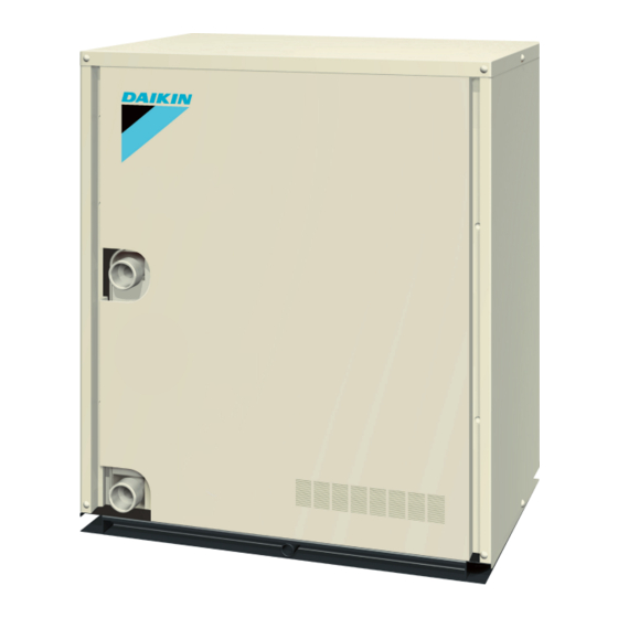
Page 24: Outside Units
SiUS30-604 External Appearance Outside Units RWEYQ60MTJU RWEYQ72MTJU RWEYQ84MTJU 5 • 6 • 7 ton RWEYQ144MTJU RWEYQ168MTJU 12 • 14 ton RWEYQ216MTJU RWEYQ252MTJU 18 • 21 ton General Information... -
Page 25: Combination Of Outside Units
12ton BHFP22MA56U, BHFP26MA56U ●● 14ton BHFP22MA56U, BHFP26MA56U ●●● 18ton BHFP22MA84U, BHFP26MA84U ●●● 21ton BHFP22MA84U, BHFP26MA84U ★Note: For multiple connection of 12 ton ~ 21 ton system, an optional Daikin Multi Connection Piping Kit for Outside Unit is required. General Information... -
Page 26: Capacity Range
SiUS30-604 Capacity Range 5. Capacity Range Outside Units Capacity Range 5ton 6ton 7ton 12ton 14ton 18ton 21ton RWEYQ 144M 168M 216M 252M Max. Number of Connectable Indoor Units Total Capacity Index of Indoor Units to be 93.5 327.5 Connected Indoor Units Capacity Range 0.6ton 0.8ton... - Page 27 Capacity Range SiUS30-604 General Information...
-
Page 28: Part 2 Specifications
SiUS30-604 Part 2 Specifications 1. Specifications ....................16 1.1 Outside Units....................16 1.2 BS Units ..................... 23 1.3 Indoor Units ....................24 Specifications... -
Page 29: Specifications
Specifications SiUS30-604 1. Specifications Outside Units Model Name RWEYQ60MTJU ★ 1 Cooling Capacity Btu / h 60,000 ★ 2 Heating Capacity Btu / h 67,500 Casing Color Ivory White (5Y7.5/1) Dimensions: (H×W×D) 39-3/8×30-3/4×21-11/16 Heat Exchanger Stainless Steel Plate Type Type Hermetically Sealed Scroll Type Piston Displacement m³/h... - Page 30 SiUS30-604 Specifications Model Name RWEYQ72MTJU ★ 1 Cooling Capacity Btu / h 72,000 ★ 2 Heating Capacity Btu / h 81,000 Casing Color Ivory White (5Y7.5/1) Dimensions: (H×W×D) 39-3/8×30-3/4×21-11/16 Heat Exchanger Stainless Steel Plate Type Type Hermetically Sealed Scroll Type Piston Displacement m³/h 11.18...
- Page 31 Specifications SiUS30-604 Model Name (Combination Unit) RWEYQ84MTJU ★ 1 Cooling Capacity Btu / h 84,000 ★ 2 Heating Capacity Btu / h 94,500 Casing Color Ivory White (5Y7.5/1) Dimensions: (H×W×D) 39-3/8×30-3/4×21-11/16 Heat Exchanger Stainless Steel Plate Type Type Hermetically Sealed Scroll Type Piston Displacement m³/h 13.66...
- Page 32 SiUS30-604 Specifications Model Name (Combination Unit) RWEYQ144MTJU Model Name (Combination Unit) RWEYQ72MTJU+RWEYQ72MTJU ★ 1 Cooling Capacity Btu / h 144,000 ★ 2 Heating Capacity Btu / h 162,000 Casing Color Ivory White (5Y7.5/1) Dimensions: (H×W×D) (39-3/8×30-3/4×21-11/16)×2 Heat Exchanger Stainless Steel Plate Type Type Hermetically Sealed Scroll Type Piston Displacement...
- Page 33 Specifications SiUS30-604 Model Name (Combination Unit) RWEYQ168MTJU Model Name (Combination Unit) RWEYQ84MTJU+RWEYQ84MTJU ★ 1 Cooling Capacity Btu / h 168,000 ★ 2 Heating Capacity Btu / h 189,000 Casing Color Ivory White (5Y7.5/1) Dimensions: (H×W×D) (39-3/8×30-3/4×21-11/16)×2 Heat Exchanger Stainless Steel Plate Type Type Hermetically Sealed Scroll Type Piston Displacement...
- Page 34 SiUS30-604 Specifications Model Name (Combination Unit) RWEYQ216MTJU Model Name (Combination Unit) RWEYQ72MTJU+RWEYQ72MTJU+RWEYQ72MTJU ★ 1 Cooling Capacity Btu / h 216,000 ★ 2 Heating Capacity Btu / h 243,000 Casing Color Ivory White (5Y7.5/1) Dimensions: (H×W×D) (39-3/8×30-3/4×21-11/16)×3 Heat Exchanger Stainless Steel Plate Type Type Hermetically Sealed Scroll Type Piston Displacement...
- Page 35 Specifications SiUS30-604 Model Name (Combination Unit) RWEYQ252MTJU Model Name (Combination Unit) RWEYQ84MTJU+RWEYQ84MTJU+RWEYQ84MTJU ★ 1 Cooling Capacity Btu / h 252,000 ★ 2 Heating Capacity Btu / h 283,500 Casing Color Ivory White (5Y7.5/1) Dimensions: (H×W×D) (39-3/8×30-3/4×21-11/16)×3 Heat Exchanger Stainless Steel Plate Type Type Hermetically Sealed Scroll Type Piston Displacement...
-
Page 36: Bs Units
SiUS30-604 Specifications BS Units Model BSVQ36MVJU BSVQ60MVJU Power Supply 60Hz 208~230V 60Hz 208~230V Total Capacity Index of Connectable Indoor Unit Less than 36 Less than 60 No. of Connectable Indoor Units Max. 3 Max. 5 Casing Galvanized Steel Plate Galvanized Steel Plate Dimensions: (H×W×D) 7-1/4 ×... -
Page 37: Indoor Units
Specifications SiUS30-604 Indoor Units Ceiling Mounted Cassette Type (Multi-Flow) Model FXFQ12MVJU FXFQ18MVJU FXFQ24MVJU ★ 1 Cooling Capacity Btu/h 12,000 18,000 24,000 ★ 2 Heating Capacity Btu/h 13,500 20,000 27,000 Casing / Color Galvanized Steel Plate Galvanized Steel Plate Galvanized Steel Plate Dimensions: (H×W×D) 9-1/8 ×... - Page 38 SiUS30-604 Specifications Ceiling Mounted Cassette Type (Multi-Flow) Model FXFQ30MVJU FXFQ36MVJU ★ 1 Cooling Capacity Btu/h 30,000 36,000 ★ 2 Heating Capacity Btu/h 34,000 40,000 Casing / Color Galvanized Steel Plate Galvanized Steel Plate Dimensions: (H×W×D) 11-3/8 × 33-1/8 × 33-1/8 11-3/8 ×...
- Page 39 Specifications SiUS30-604 Slim Ceiling Mounted Duct Type Model FXDQ07MVJU FXDQ09MVJU FXDQ12MVJU ★ 1 Cooling Capacity Btu/h 7,500 9,500 12,000 ★ 2 Heating Capacity Btu/h 8,500 10,500 13,500 Casing / Color Galvanized Steel Plate Galvanized Steel Plate Galvanized Steel Plate Dimensions: (H×W×D) 7-7/8 ×...
- Page 40 SiUS30-604 Specifications Slim Ceiling Mounted Duct Type Model FXDQ18MVJU FXDQ24MVJU ★ 1 Cooling Capacity Btu/h 18,000 24,000 ★ 2 Heating Capacity Btu/h 20,000 27,000 Casing / Color Galvanized Steel Plate Galvanized Steel Plate Dimensions: (H×W×D) 7-7/8 × 35-7/16 × 24-7/16 7-7/8 ×...
- Page 41 Specifications SiUS30-604 Ceiling Mounted Built-In Type Model FXSQ12MVJU FXSQ18MVJU FXSQ24MVJU ★ 1 Cooling Capacity Btu/h 12,000 18,000 24,000 ★ 2 Heating Capacity Btu/h 13,500 20,000 27,000 Casing / Color Galvanized Steel Plate Galvanized Steel Plate Galvanized Steel Plate Dimensions: (H×W×D) 11-7/8 ×...
- Page 42 SiUS30-604 Specifications Ceiling Mounted Built-In Type Model FXSQ30MVJU FXSQ36MVJU FXSQ48MVJU ★ 1 Cooling Capacity Btu/h 30,000 36,000 48,000 ★ 2 Heating Capacity Btu/h 34,000 40,000 54,000 Casing / Color Galvanized Steel Plate Galvanized Steel Plate Galvanized Steel Plate Dimensions: (H×W×D) 11-7/8 ×...
- Page 43 Specifications SiUS30-604 Ceiling Mounted Duct Type Model FXMQ30MVJU FXMQ36MVJU FXMQ48MVJU ★ 1 Cooling Capacity Btu/h 30,000 36,000 48,000 ★ 2 Heating Capacity Btu/h 34,000 40,000 54,000 Casing / Color Galvanized Steel Plate Galvanized Steel Plate Galvanized Steel Plate Dimensions: (H×W×D) 15-3/8 ×...
-
Page 44: Ceiling Suspended Type
SiUS30-604 Specifications Ceiling Suspended Type Model FXHQ12MVJU FXHQ24MVJU FXHQ36MVJU ★ 1 Cooling Capacity Btu/h 12,000 24,000 36,000 ★ 2 Heating Capacity Btu/h 13,500 27,000 40,000 Casing Color White (10Y9/0.5) White (10Y9/0.5) White (10Y9/0.5) Dimensions: (H×W×D) 7-11/16×37-13/16×26-3/4 7-11/16×55-1/8×26-3/4 7-11/16×62-5/8×26-3/4 Rows×Stages×FPI 2×12×15 3×12×15 2×12×15+2×10×15 Coil (Cross... - Page 45 Specifications SiUS30-604 Wall Mounted Type Model FXAQ07MVJU FXAQ09MVJU FXAQ12MVJU ★ 1 Cooling Capacity Btu/h 7,500 9,500 12,000 ★ 2 Heating Capacity Btu/h 8,500 10,500 13,500 Casing Color White (3.0Y8.5/0.5) White (3.0Y8.5/0.5) White (3.0Y8.5/0.5) Dimensions: (H×W×D) 11–3/8×31–1/4×9 11–3/8×31–1/4×9 11–3/8×31–1/4×9 Rows×Stages×FPI 2×14×17 2×14×17 2×14×17 Coil (Cross...
- Page 46 SiUS30-604 Specifications Wall Mounted Type Model FXAQ18MVJU FXAQ24MVJU ★ 1 Cooling Capacity Btu/h 18,000 24,000 ★ 2 Heating Capacity Btu/h 20,000 27,000 Casing Color White (3.0Y8.5/0.5) White (3.0Y8.5/0.5) Dimensions: (H×W×D) 11–3/8×41–3/8×9 11–3/8×41–3/8×9 Rows×Stages×FPI 2×14×17 2×14×17 Coil (Cross Fin Coil) Face Area ft²...
-
Page 47: Floor Standing Type
Specifications SiUS30-604 Floor Standing Type Model FXLQ12MVJU FXLQ18MVJU FXLQ24MVJU ★ 1 Cooling Capacity Btu/h 12,000 18,000 24,000 ★ 2 Heating Capacity Btu/h 13,500 20,000 27,000 Casing Color Ivory White (5Y7.5/1) Ivory White (5Y7.5/1) Ivory White (5Y7.5/1) Dimensions: (H×W×D) 23–5/8×44–7/8×8–3/4 23–5/8×55–7/8×8–3/4 23–5/8×55–7/8×8–3/4 Rows×Stages×FPI 3×14×17... - Page 48 SiUS30-604 Specifications Concealed Floor Standing Type Model FXNQ12MVJU FXNQ18MVJU FXNQ24MVJU ★ 1 Cooling Capacity Btu/h 12,000 18,000 24,000 ★ 2 Heating Capacity Btu/h 13,500 20,000 27,000 Casing Color Galvanized Steel Plate Galvanized Steel Plate Galvanized Steel Plate Dimensions: (H×W×D) 24×42–1/8×8–5/8 24×53–1/8×8–5/8 24×53–1/8×8–5/8 Rows×Stages×FPI...
- Page 49 Specifications SiUS30-604 Specifications...
-
Page 50: Part 3 Refrigerant Circuit
SiUS30-604 Part 3 Refrigerant Circuit 1. Refrigerant Circuit ..................38 RWEYQ60MTJU / RWEYQ72MTJU / RWEYQ84MTJU......38 1.2 BSVQ36, 60M .................... 40 2. Functional Parts Layout ................41 RWEYQ60MTJU / RWEYQ72MTJU / RWEYQ84MTJU......41 3. Refrigerant Flow for Each Operation Mode..........43 3.1 In Case of Heat Pump Connection............. 43 3.2 In Case of Heat Recovery Connection (One Outside Unit Installation) .............. -
Page 51: Refrigerant Circuit
Refrigerant Circuit SiUS30-604 1. Refrigerant Circuit RWEYQ60MTJU / RWEYQ72MTJU / RWEYQ84MTJU No. in refrigerant Symbol Name Major Function system diagram Inverter compressor is operated on frequencies between 52 Hz and 230 Hz by using the inverter. The number of operating steps is as follows. Inverter compressor (INV) In cooling operation: High pressure control Electronic expansion valve... - Page 52 SiUS30-604 Refrigerant Circuit RWEYQ60MTJU / RWEYQ72MTJU / RWEYQ84MTJU 4D055410 Refrigerant Circuit...
-
Page 53: Bsvq36, 60M
Refrigerant Circuit SiUS30-604 BSVQ36, 60M Symbol Name Major function Solenoid valve (20RT) (For liquid pipe) Super-cools liquid refrigerant in the heating operation unit during cooling/heating simultaneous operation, in order to prevent capacity reducing in cooling operation unit caused by flash gas generated in the liquid pipe Solenoid valve (20RH) Used to changeover the cooling and heating operation of indoor units 4D045338... -
Page 54: Functional Parts Layout
SiUS30-604 Functional Parts Layout 2. Functional Parts Layout RWEYQ60MTJU / RWEYQ72MTJU / RWEYQ84MTJU 2.1.1 Functional Parts Layout (Solenoid Valve etc.) Electronic expansion valve (Y3E) Solenoid valve (Y3S) 4way Valve (20S1, Y5S) Solenoid valve (Y6S) Stop valve 4way Valve (20S2, Y7S) (Liquid side) Stop valve (Discharge gas side) -
Page 55: Front View
Functional Parts Layout SiUS30-604 2.1.2 Sensors Plan R4T Thermistor (Heat-exchanger gas pipe) R3T Thermistor (M1C, Discharge pipe) Front View R5T Thermistor (Sub cooling heat-exchanger) R6T Thermistor (Receiver liquid pipe) R2T Thermistor (Suction pipe) Refrigerant Circuit... -
Page 56: Refrigerant Flow For Each Operation Mode
SiUS30-604 Refrigerant Flow for Each Operation Mode 3. Refrigerant Flow for Each Operation Mode In Case of Heat Pump Connection A. Cooling Operation Refrigerant Circuit... - Page 57 Refrigerant Flow for Each Operation Mode SiUS30-604 B. Heating Operation Refrigerant Circuit...
-
Page 58: In Case Of Heat Recovery Connection (One Outside Unit Installation)
SiUS30-604 Refrigerant Flow for Each Operation Mode In Case of Heat Recovery Connection (One Outside Unit Installation) A. Cooling Operation Refrigerant Circuit... - Page 59 Refrigerant Flow for Each Operation Mode SiUS30-604 B. Heating and simultaneous cooling/heating operation (When the outdoor water cooled heat exchanger is used as condenser.) Refrigerant Circuit...
- Page 60 SiUS30-604 Refrigerant Flow for Each Operation Mode C. Heating and simultaneous cooling heating operation mode (When the outdoor water cooled heat exchanger is used as evaporator.) (In case there are indoor units operating with cooling thermostat “ON”.) Refrigerant Circuit...
- Page 61 Refrigerant Flow for Each Operation Mode SiUS30-604 Refrigerant Circuit...
-
Page 62: In Case Of Heat Recovery Connection (3 Outside Units Connection.)
SiUS30-604 Refrigerant Flow for Each Operation Mode In Case of Heat Recovery Connection (3 Outside units Connection.) A. Cooling Operation To other indoor units High temperature, high pressure gas High temperature, high pressure liquid Bs unit Indoor unit Low temperature, low pressure liquid or gas Fan ON Outside unit 1 Outside unit 2... - Page 63 Refrigerant Flow for Each Operation Mode SiUS30-604 B: Heating and simultaneous cooling/heating operation mode (When the outdoor water cooled heat exchangers are used only as condenser.) To other indoor units High temperature, high pressure gas High temperature, high pressure liquid Bs unit Indoor unit Low temperature, low pressure liquid or gas...
- Page 64 SiUS30-604 Refrigerant Flow for Each Operation Mode C: Heating and simultaneous cooling/heating operation mode (When the outdoor water cooled heat exchangers are used as condenser and evaporator mixed.) To other indoor units High temperature, high pressure gas High temperature, high pressure liquid Bs unit Indoor unit Outside unit 1...
- Page 65 Refrigerant Flow for Each Operation Mode SiUS30-604 D: Heating and simultaneous cooling/heating operation mode (When the outdoor water cooled heat exchangers are used only as evaporator.) High temperature, high pressure gas To other indoor units High temperature, high pressure liquid Bs unit Indoor unit Low temperature, low pressure liquid or gas...
-
Page 66: Part 4 Function
SiUS30-604 Part 4 Function 1. Function General..................55 1.1 Symbol ....................... 55 1.2 Operation Mode..................56 1.3 Normal Operation ..................57 1.4 BS unit & Indoor unit operation mode detail..........58 2. Stop......................59 2.1 Stopping Operation ..................59 3. Standby .....................61 3.1 Restart Standby.................. - Page 67 SiUS30-604 9.8 Heater Control .................... 90 9.9 List of Swing Flap Operations ..............91 9.10 Freeze Prevention ..................92 Function...
-
Page 68: Function General
SiUS30-604 Function General 1. Function General Symbol Symbol Electric symbol Description or function 20S1 Four way valve (Main) 20S2 Four way valve (For heat exchanger) — Discharge pipe superheat DSHi — Discharge pipe superheat of inverter compressor (Y1E, Y3E) Opening of electronic expansion valve Electronic expansion valve for water heat exchanger Electronic expansion valve for sub-coolig heat exchanger Value of INV compressor discharge pie temperature (R3T) compensated with outdoor air... -
Page 69: Operation Mode
Function General SiUS30-604 Operation Mode System stopping function (2.1) • Restart standby (3.1) Thermostat ON • Clankcase heater control (3.2) Startup control • Cooling startup control (4.1) • Heating startup control (4.2) • Pump-down residual operation (7.3) • Pressure equalization startup control (4.3) Normal operation Thermostat OFF... -
Page 70: Normal Operation
SiUS30-604 Function General Normal Operation Actuator function Electrical Parts name Symbol Normal heating or normal cooling/ symbol Normal cooling heating simultaneous operation PI control, High pressure protection, PI control, High pressure protection, Low pressure protection, Discharge Low pressure protection, Discharge Compressor —... -
Page 71: Bs Unit & Indoor Unit Operation Mode Detail
Function General SiUS30-604 BS unit & Indoor unit operation mode detail Outside unit operation mode Cooling/Heating Cooling mode Heating mode Stopping mode 20RH 20RT Thermostat ON Depend on Depend on Indoor Fan remote controller remote controller Indoor EV Indoor unit control Indoor unit control 20RH 20RT Cooling... -
Page 72: Stop
SiUS30-604 Stop 2. Stop Stopping Operation This operation is used to define the operation of the actuator while the system stops. 2.1.1 When System is in Stop Mode Electrical Parts name Symbol Actuator function symbol Compressor — (M1C) Inverter cooling fan —... - Page 73 Stop SiUS30-604 In heating operation or simultaneously in cooling / heating operation : The system operates in mode A or mode B listed in the table below. Electrical Parts name Symbol Mode A operation Mode B operation symbol Compressor — (M1C) Inverter cooling fan —...
-
Page 74: Standby
SiUS30-604 Standby 3. Standby Restart Standby Forced standby is performed to prevent frequent repetition of ON/OFF of the compressor, and to equalize pressure in the refrigerant system. Electrical Parts name Symbol Actuator function symbol Compressor — (M1C) 0 Hz Inverter cooling fan —... -
Page 75: Startup Control
Startup Control SiUS30-604 4. Startup Control This startup control is used to provide the following control to reduce the compressor load resulting from liquid return or else during compressor startup, and also determine the position of four way valves. Cooling Start-up Control →... -
Page 76: Heating Start-Up Control
SiUS30-604 Startup Control Heating Start-up Control → Both master and slave units operate same time for changing 4 way valve position Normal operation after completion. Thermostat ON Electrical Pressure equalization Parts name Symbol Starting control symbol control before start-up 52Hz Compressor —... -
Page 77: Pressure Equalizing Control
Startup Control SiUS30-604 Pressure Equalizing Control This pressure equalization control is used to equalize the pressure of discharge piping and suction piping in order to reduce refrigerant passing noise when changing over the BS units. [Starting conditions] The temperature control of indoor units with thermostat ON does not match up with the state of the BS unit changeover valve to which the indoor units are connected. -
Page 78: Normal Control
SiUS30-604 Normal Control 5. Normal Control Compressor Control 5.1.1 Compressor Control Compressor PI Control Carries out the compressor capacity PI control to maintain Te at constant during cooling operation and Tc at constant during heating operation to ensure stable unit performance. [Cooling operation] Controls compressor capacity to adjust Te to Te : Low pressure equivalent saturation temperature... -
Page 79: Unit Installation
Normal Control SiUS30-604 5.1.2 Compressor Operation Frequency Steps 1. One outside 2. Two outside units connection installation unit installation A : 1 Compressor operation Step Master Step Master 52Hz Start-up 57Hz 52Hz 62Hz 57Hz 68Hz 62Hz 74Hz 68Hz 81Hz 74Hz 88Hz 81Hz B : 2 Compressor operation... -
Page 80: Electronic Expansion Valve Control
SiUS30-604 Normal Control Electronic Expansion Valve Control Main Electronic Expansion Valve EV1 Control Carries out the electronic expansion valve (Y1E) PI control to maintain the evaporator outlet superheated degree (SH) at constant during heating operation to make maximum use of the outside unit heat exchanger (evaporator). -
Page 81: Heat Exchange Mode In Heating Operation Or Simultaneous Cooling / Heating Operation
Normal Control SiUS30-604 Heat Exchange Mode in Heating Operation or Simultaneous Cooling / Heating Operation In heating or simultaneous cooling / heating operation, a target condensing and evaporating temperature can be secured by switching the water heat exchanger of the outside unit into evaporator or condenser with load. - Page 82 SiUS30-604 Normal Control Three outside units installation Note 1: ∆GR =Target of heat exchange Master unit Slave unit 1 Slave unit 2 capacity balance – Actual Four-way changeover valve for measurement of heat heat exchanger [Y7S] (For the (Condenser) (Condenser) (Condenser) application of heat exchanger) balance...
-
Page 83: Protection Control
Protection Control SiUS30-604 6. Protection Control High Pressure Protection Control This high pressure protection control is used to prevent the activation of protection devices due to abnormal increase of high pressure and to protect compressors against the transient increase of high pressure. -
Page 84: Low Pressure Protection Control
SiUS30-604 Protection Control Low Pressure Protection Control This low pressure protection control is used to protect compressors against the transient decrease of low pressure. [In cooling operation] ∗1 Pe: LP pressure sensor detection Normal operation value for master unit ∗2 This frequency control is carried Pe >... - Page 85 Protection Control SiUS30-604 [In heating or cooling/heating simultaneous operation] (When the outside unit heat exchanger is used as condenser.) ∗1 Pe: LP pressure sensor detection Normal operation value for each outside unit. ∗2 This frequency control is carried Compressor upper limit Pc <...
-
Page 86: Discharge Pipe Protection Control
SiUS30-604 Protection Control Discharge Pipe Protection Control This discharge pipe protection control is used to protect the compressor internal temperature against a malfunction or transient increase of discharge pipe temperature. ∗ Discharge pipe protection control is carried out in each outside unit. [INV compressor] Normal operation HTdi :Value of INV compressor discharge pipe... -
Page 87: Inverter Protection Control
Protection Control SiUS30-604 Inverter Protection Control Inverter current protection control and inverter fin temperature control are performed to prevent tripping due to a malfunction, or transient inverter overcurrent, and fin temperature increase. ∗ This control is carried out in each outside unit. [Inverter overcurrent protection control] Not limited 220-V unit... -
Page 88: Cooling Fan Control
SiUS30-604 Protection Control Cooling Fan Control his function is used for ON-OFF control of the cooling fan to cool the inverter. This cooling fan operates only when the temperature of the inverter fan is high, in order to reduce the operating time of the fan. -
Page 89: Special Operation
Special Operation SiUS30-604 7. Special Operation Oil Return Operation In order to prevent the running-out of refrigerating machine oil in the compressor, the oil flowing out from the compressor to the system side is collected through the oil return operation. 7.1.1 Oil Return Operation in Cooling Operation [Starting conditions] Start oil return operation in cooling operation referring to the following conditions. - Page 90 SiUS30-604 Special Operation 7.1.2 Oil Return Operation in Heating or Cooling/Heating simultaneous Operation [Starting conditions] Start oil return operation in heating operation referring to the following conditions. Cumulative compressor operating time after power supply turns on exceeds 2 hours and the time after the completion of previous oil return operation exceeds 8 hours.
-
Page 91: Oil Return Operation Of Water Heat Exchanger
Special Operation SiUS30-604 Oil Return Operation of Water Heat Exchanger [Oil return operation of Water heat exchanger] When the water heat exchanger is used as evaporator during heating or simultaneous cooling/ heating operation, the operation that the oil accumulated in the water heat exchanger is returned to compressor is conducted. -
Page 92: Pump-Down Residual Operation Control
SiUS30-604 Special Operation Pump-down Residual Operation Control If any liquid refrigerant remains in the heat exchanger during compressor startup, the liquid refrigerant will enter the compressor, resulting in the dilution of the refrigerating machine oil in the compressor and the degradation of lubricating capacity. Therefore, before the compressor stops, pump-down operation is performed to collect the refrigerant in the heat exchanger. - Page 93 Special Operation SiUS30-604 7.3.2 Heating & Simultaneous Cooling/Heating Mode Electrical Parts name Symbol Master unit operation Slave unit operation symbol Compressor — (M1C) Current step Inverter cooling fan — (M1, 2F) Inverter cooling fan control Inverter cooling fan control 4 way valve 1 20S1 (Y5S) 4 way valve 2...
-
Page 94: Refrigerant Drift Prevention
SiUS30-604 Special Operation Refrigerant Drift Prevention “Refrigerant drift prevention control” is carried out, in order to prevent refrigerant drift among outside units during heating operation using outside multiple connection. Excessively charged refrigerant in outside units are collected and transferred to other outside units that are running out of gas by controlling the solenoid valve. -
Page 95: Other Control
Other Control SiUS30-604 8. Other Control Outside Unit Rotation In the case of multi-outside-unit system, this outside unit rotation is used to prevent the compressor from burning out due to unbalanced oil level between outside units. [Details of outside unit rotation] In the case of multi-outside-unit system, each outside unit is given an operating priority for the control. -
Page 96: Outline Of Control (Indoor Unit)
SiUS30-604 Outline of Control (Indoor Unit) 9. Outline of Control (Indoor Unit) Drain Pump Control 1. The drain pump is controlled by the ON/OFF buttons (4 button (1) - (4) given in the figure below). 9.1.1 When the Float Switch is Tripped While the Cooling Thermostat is ON: ∗... - Page 97 Outline of Control (Indoor Unit) SiUS30-604 9.1.3 When the Float Switch is Tripped During Heating Operation: During heating operation, if the float switch is not reset even after the 5 minutes operation, 5 seconds stop, 5 minutes operation cycle ends, operation continues until the switch is reset. 9.1.4 When the Float Switch is Tripped and “AF”...
-
Page 98: Louver Control For Preventing Ceiling Dirt
SiUS30-604 Outline of Control (Indoor Unit) Louver Control for Preventing Ceiling Dirt We have added a control feature that allows you to select the range of in which air direction can be adjusted in order to prevent the ceiling surrounding the air discharge outlet of ceiling mounted cassette type units from being soiled. -
Page 99: Thermostat Sensor In Remote Controller
Outline of Control (Indoor Unit) SiUS30-604 Thermostat Sensor in Remote Controller Temperature is controlled by both the thermostat sensor in remote controller and air suction thermostat in the indoor unit. (This is however limited to when the field setting for the thermostat sensor in remote controller is set to “Use”.) Cooling If there is a significant difference in the preset temperature and the suction temperature, fine... - Page 100 SiUS30-604 Outline of Control (Indoor Unit) Heating When heating, the hot air rises to the top of the room, resulting in the temperature being lower near the floor where the occupants are. When controlling by body thermostat sensor only, the unit may therefore be turned off by the thermostat before the lower part of the room reaches the preset temperature.
-
Page 101: Thermostat Control While In Normal Operation
Outline of Control (Indoor Unit) SiUS30-604 Thermostat Control While in Normal Operation VRV multi systems are set at factory to thermostat control mode using the remote controller. While in normal thermostat differential control mode (i.e., factory set mode), the thermostat turns OFF when the system reaches a temperature of -1.8°F from the set temperature while in cooling operation or of +1.8°F from that while in heating operation. -
Page 102: Electronic Expansion Valve Control
SiUS30-604 Outline of Control (Indoor Unit) Electronic expansion Valve Control • Electronic expansion Valve Control In cooling, to maximize the capacity of indoor unit heat exchanger (evaporator), operate the electronic expansion valve under PI control so that the evaporator outlet superheated degree (SH) will become constant. -
Page 103: Heater Control
Outline of Control (Indoor Unit) SiUS30-604 Heater Control The heater control is conducted in the following manner. [Normal control] While in heating operation, the heater Set temperature control (ON/OFF) is conducted as shown on the right. 3.6ºF 3.6ºF [Overload control] When the system is overloaded in heating operation, the heater will be 109.4ºF... -
Page 104: List Of Swing Flap Operations
SiUS30-604 Outline of Control (Indoor Unit) List of Swing Flap Operations Swing flaps operate as shown in table below. Flap FXFQ FXHQ FXAQ Swing Horizontal Horizontal Horizontal Hot start from defrosting operation Wind direction set Horizontal Horizontal Horizontal Swing Horizontal Horizontal Horizontal Defrosting operation... -
Page 105: Freeze Prevention
Outline of Control (Indoor Unit) SiUS30-604 9.10 Freeze Prevention Freeze When the temperature detected by liquid pipe temperature thermistor (R2T) of the indoor unit heat exchanger drops too low, the unit enters freeze prevention operation in accordance with the Prevention by Off following conditions, and is also set in accordance with the conditions given below. -
Page 106: Part 5 Test Operation
SiUS30-604 Part 5 Test Operation 1. Test Operation ..................94 Procedure and Outline ................94 2. Outside Unit PC Board Layout ..............98 3. Field Setting ....................99 3.1 Field Setting from Remote Controller ............99 3.2 Field Setting from Outside Unit ..............110 Test Operation... -
Page 107: Test Operation
Test Operation SiUS30-604 1. Test Operation Procedure and Outline Follow the following procedure to conduct the initial test operation after installation. 1.1.1 Check Work Prior to Turn Power Supply On Check the below items. Is the wiring performed as specified? 2Power wiring Are the designated wires used? 2Control transmission wiring... - Page 108 SiUS30-604 Test Operation 8ON1OFF9Blink Micro CH selection computer MODE TEST Demand Multi normal noise LED display (Factory set) Master Slave monitor 1 outside unit installation master outside unit multi slave1 installation(*) slave2 * The outside unit connected the control wires (F1 and F2) for the indoor unit should be designated as master unit.
-
Page 109: Check Operation
Test Operation SiUS30-604 1.1.3 Check Operation Be sure to conduct the check operation. If the check operation is not conducted, the malfunction code “U3” will be displayed on the remote controller, thus disabling the normal operation. Through the following procedure, the check operation is automatically conducted. A period of approximately 20 minutes (approximately 30 minutes at maximum) is required to complete the judgment. - Page 110 SiUS30-604 Test Operation [LED display in the case of multi-outside-unit system] (Same as that in emergency operation) * Discriminate the operating status of the master unit/slave units through the following LED display. LED display (7:ON :OFF :Blink) H1P---H7P H8P Master: 7777777 7777 7 Slave 1:...
-
Page 111: Outside Unit Pc Board Layout
Outside Unit PC Board Layout SiUS30-604 2. Outside Unit PC Board Layout Outside unit PC board (1) Microcomputer normal monitor (2) Set mode display (LED) H1P H2P H3P H4P H5P H6P H7P (3) Mode setting switch MODE RETURN TEST RESET 1 2 3 4 1 2 3 4 (4) Local setting switch... -
Page 112: Field Setting
SiUS30-604 Field Setting Field Setting Field Setting from Remote Controller Individual function of indoor unit can be changed from the remote controller. At the time of installation or after service inspection / repair, make the local setting in accordance with the following description. - Page 113 Field Setting SiUS30-604 3.1.2 Wireless Remote Controller - Indoor Unit BRC7C812 BRC4C82 BRC7E818 BRC7E83 1. When in the normal mode, push the button for 4 seconds or more, and operation then enters the “field set mode”. 2. Select the desired “mode No.” with the button.
-
Page 114: Simplified Remote Controller
SiUS30-604 Field Setting 3.1.3 Simplified Remote Controller BRC2A71 Group No. setting by simplified remote controller. 1. Remove the cover of remote controller. 2. While in normal mode, press the [BS6] BUTTON (field set) to enter the FIELD SET MODE. ▲ 3. - Page 115 Field Setting SiUS30-604 3.1.4 Setting Contents and Code No. – VRV Indoor Unit Mode Setting Setting Contents Second Code No.(Note 3) Switch system indoor Note 2 unit 10(20) Filter contamination heavy/ Super Light Approx. Heavy Approx. — — settings light (Setting for display long life 10,000 5,000...
-
Page 116: Detailed Explanation Of Setting Modes
SiUS30-604 Field Setting 3.1.5 Applicable range of Field setting Ceiling Slim Ceiling Ceiling Ceiling Ceiling Wall mounted Floor Concealed mounted mounted duct mounted mounted duct Suspended type standing type Floor cassette type type built-in type type type standing type Multi flow FXFQ FXSQ FXMQ... -
Page 117: External On/Off Input
Field Setting SiUS30-604 External ON/OFF input This input is used for “ON / OFF operation” and “Protection device input” from the outside. The input is performed from the T1-T1 terminal of the operation terminal block (X1A) in the electric component box. F2 T1 T2 Forced stop Input A... - Page 118 SiUS30-604 Field Setting Air Flow Adjustment - Ceiling height Make the following setting according to the ceiling height. The setting position No. is set to “01” at the factory. In the Case of FXAQ07~24, FXHQ12~36 Setting Switch Setting Position Mode No. Setting Wall-mounted type: Standard 13 (23)
- Page 119 Field Setting SiUS30-604 3.1.7 Centralized Control Group No. Setting BRC1C Type If carrying out centralized control by central remote controller or unified ON/OFF controller, group No. must be set for each group individually by remote controller. Group No. setting by remote controller for centralized control 1.
-
Page 120: Brc7C Type
SiUS30-604 Field Setting BRC7C Type Group No. setting by wireless remote controller for centralized control 1. When in the normal mode, push button for 4 seconds or more, and operation then enters BRC4C Type the “field set mode”. BRC7E Type 2. -
Page 121: Contents Of Control Modes
Field Setting SiUS30-604 3.1.8 Setting of Operation Control Mode from Remote Controller (Local Setting) The operation control mode is compatible with a variety of controls and operations by limiting the functions of the operation remote controller. Furthermore, operations such as remote controller ON/ OFF can be limited in accordance with the combination conditions. - Page 122 SiUS30-604 Field Setting Selection of Select whether to accept or to reject the operation from the remote controller regarding the operation, stop, temperature setting and operation mode setting, respectively, and determine the particular control Control Mode mode from the rightmost column of the table below. (Example) Operation by remote Operation by remote...
-
Page 123: Field Setting From Outside Unit
Field Setting SiUS30-604 Field Setting from Outside Unit 3.2.1 Field Setting from Outside Unit Setting by dip switches The following field settings are made by dip switches on PC board. Dipswitch Setting item Description Setting Used to set cool/heat select by remote controller DS1-1 Cool/Heat select equipped with outside unit. - Page 124 SiUS30-604 Field Setting Setting by pushbutton switches The following settings are made by pushbutton switches on PC board. In case of multi-outside unit system, various items should be set with the master unit. (Setting with the slave unit is disabled.) The master unit and slave unit can be discriminated with the LED indication as shown below.
- Page 125 Field Setting SiUS30-604 a. “Setting mode 1” “Normally, “Setting mode 1” is set. In case of other status, push MODE button (BS1) one time and set to “Setting mode 1”. <Selection of setting items> LED display example Push the SET button (BS2) and set Setting (displaying) item LED display to a setting item you want.
- Page 126 SiUS30-604 Field Setting b. “Setting mode 2” Setting item Description Cool/heat unified Sets address for cool/heat unified operation. address Push and hold the MODE button (BS1) for 5 seconds and set to demand address Address for demand operation “Setting mode 2”. Number of units for Sets the number of units for sequential starting.
- Page 127 Field Setting SiUS30-604 Setting item Description Emergency operation (Setting for the master unit operation prohibition in multi- outside-unit system) Emergency operation (Setting for the Used to temporarily prohibit the applicable outside unit from slave unit 1 operating should there be any faulty part in multi-outside-unit operation system.
- Page 128 SiUS30-604 Field Setting Setting item display C/H selection Setting condition display MODE TEST Low noise Demand Setting item Master Slave ∗ Factory set 8777777 ∗ Address Binary number 8777778 Cool / Heat Unified address (6 digits) 8788888 8777777 ∗ Address Binary number 8777778 Low noise/demand...
- Page 129 Field Setting SiUS30-604 Setting item display C/H selection Setting condition display MODE TEST Low noise Demand Setting item Master Slave ∗ Factory set 8777778 ∗ 28 Power transistor check mode 8777787 60 % demand 8777778 8777787 ∗ 30 Demand setting 1 70 % demand 80 % demand 8777877...
- Page 130 SiUS30-604 Field Setting c. Monitor mode LED display Setting item Data display Operation/backup operation To enter the monitor mode, push the 9 7 7 7 7 7 7 See below setting MODE button (BS1) when in “Setting mode 1”. 9 7 7 7 7 7 8 C/H unified address 9 7 7 7 7 8 7 Low noise/demand address...
- Page 131 Field Setting SiUS30-604 Setting item 0 Display contents of “Operation/backup operation setting, and others” Operation /backup operation 9 7 7 8 7 7 7 setting 9 7 7 7 7 7 7 Te setting 9 7 7 7 7 8 7 9 7 7 7 7 9 7 9 7 7 7 7 7 7 Tc setting...
- Page 132 SiUS30-604 Field Setting 3.2.2 Cool / Heat Mode Switching (In case of heating and simultaneous cooling / heating) operation connection Set Cool/Heat Separately for Each BS Unit by Cool/Heat Selector. Set remote controller change over switch (SS1, SS2) as following: •...
- Page 133 Field Setting SiUS30-604 3.2.3 Cool / Heat Mode Switching There are the following 4 cool/heat switching modes. Set cool/heat separately for each outdoor unit system by indoor unit remote controller. Set cool/heat separately for each outdoor unit system by cool/heat selector. Set cool/heat for more than one outdoor unit system simultaneously in accordance with unified master outdoor unit by indoor unit remote controller.
- Page 134 SiUS30-604 Field Setting Set Cool / Heat Separately for Each Outdoor Unit System by Cool / Heat Selector It does not matter whether or not there is outdoor - outdoor unit wiring. Set outdoor unit PC board DS1-1 to OUT (factory set). Set cool/heat switching to IND (individual) for “Setting mode 1”...
- Page 135 Field Setting SiUS30-604 Set Cool / Heat for More Than One Outside Unit System Simultaneously in Accordance with Unified Master Outside Unit by Indoor Unit Remote Controller Install the outside unit external control adapter on either the outside unit-outside unit, indoor- outside, or transmission line.
- Page 136 SiUS30-604 Field Setting Set Cool / Heat for More Than One Outside Unit System Simultaneously in Accordance with Unified Master Outside Unit by Cool/Heat Switching Remote Controller Add and change the following items to ★ Install cool/heat switching remote controller on the group master outside unit. ★...
- Page 137 Field Setting SiUS30-604 Address setting for (Set lower 5 digits with binary number.) [No.0 to No.31] Adapter PCB Address Outside unit PCB LED Set with setting mode 2 No 0 77777 No 1 77778 No 2 77787 No 3 77788 No 4 77877 No 30...
- Page 138 SiUS30-604 Field Setting 3.2.4 Setting of Demand Operation In order to save the power consumption, the capacity of outside unit is saved with control forcibly by using “Demand 1 Setting” or “Demand 2 Setting”. To operate the unit with this mode, additional setting of “Normal Demand Setting” or external input by external control adapter is required.
- Page 139 Field Setting SiUS30-604 Setting of Demand Operation By connecting the external contact input to the demand input of the outside unit external control adapter (optional), the power consumption of unit operation can be saved suppressing the compressor operating condition. A. When the demand operation is carried out by external instructions (with the use of the external control adapter for outside unit).
-
Page 140: Image Of Operation In The Case Of A
SiUS30-604 Field Setting Image of operation in the case of A Power consumption The power Rated power consumption consumption during Demand level 1 instructing Demand level 2 instructing Demand level 3 instructing the demand level 1 80 % of rated power consumption instructing can be 70 % of rated power consumption set with the... - Page 141 Field Setting SiUS30-604 Detailed Setting Procedure and Demand Control 1. Setting mode 1 (H1P off) → In setting mode 2, push the BS1 (MODE button) one time. Setting mode 2 is entered and H1P lights. During the setting mode 1 is displayed, “In low noise operation” and “In demand control” are displayed.
- Page 142 SiUS30-604 Field Setting 3.2.5 Setting of Refrigerant Additional Charging Operation When additional refrigerant is not charged all with outside unit in stop mode, operate the outside unit and charge the liquid refrigerant from the service port of liquid stop value. The additional charging operation is activated by pushbutton switch on the outside unit PC board.
- Page 143 Field Setting SiUS30-604 Caution Refrigerant cannot be charged until field wiring has been completed. Refrigerant may only be charged after performing the leak test and the vacuum drying. When charging a system, care shall be taken that its maximum permissible charge is never exceeded, in view of the danger of liquid hammer.
- Page 144 SiUS30-604 Field Setting Procedures for charging additional refrigerant. Additional refrigerant charge procedure (2)-by Additional refrigerant charge operation To learn the system settings for additional refrigerant charging, refer to the [Service Precaution] label attached on the back of the electric box lid in the outside unit. 1.
- Page 145 Field Setting SiUS30-604 Closing stop valve 1. Remove the cap and turn the valve clockwise with the hexagon wrench. 2. Securely tighten the valve until the shaft contacts the main body seal. 3. Make sure to tighten the cap securely. * For the tightening torque, refer to the table on the below.
- Page 146 SiUS30-604 Field Setting 3.2.6 Setting of Refrigerant Recovery Mode When carrying out the refrigerant collection on site, fully open the respective expansion valve of indoor and outside units [Operation procedure] In setting mode 2 with units in stop mode, set “B Refrigerant Recovery / Vacuuming mode” to ON.
- Page 147 Field Setting SiUS30-604 3.2.8 Check Operation To prevent any trouble in the period of installation at site, the system is provided with a test operation mode enabling check for incorrect wiring, stop valve left in closed, coming out (or misplacing with suction pipe thermistor) of discharge pipe thermistor and judgment of piping length, refrigerant overcharging, and learning for the minimum opening degree of motorized valve.
-
Page 148: Emergency Operation
SiUS30-604 Field Setting 3.2.9 Power Transistor Check Operation When the inverter system malfunctions (malfunction of inverter, INV compressor), to locate where the malfunction occurs, switching to the power transistor check mode of inverter in the service mode setting enables not to judge the position detection signal malfunction but to output waveform only during inverter operation. - Page 149 Field Setting SiUS30-604 Emergency operation with settings in service mode ∗ “Inhibition of operation” is set with each outside unit. Make the following settings with the master unit. (Setting with the slave unit becomes disabled.) ∗ Discriminate the operating status of the master unit/slave units through the following LED display.
-
Page 150: Part 6 Troubleshooting
SiUS30-604 Part 6 Troubleshooting 1. Troubleshooting by Remote Controller ...........140 1.1 The INSPECTION / TEST Button............. 140 1.2 Self-diagnosis by Wired Remote Controller ..........141 1.3 Self-diagnosis by Wireless Remote Controller ......... 142 1.4 Operation of the Remote Controller’s Inspection / Test Operation Button ................ - Page 151 SiUS30-604 2.28 “L1” Outdoor Unit: Malfunction of PC Board ..........195 2.29 “L4” Outside Unit: Malfunction of Inverter Radiating Fin Temperature Rise (R1T) ................196 2.30 “L5” Outside Unit: Inverter Compressor Abnormal ........197 2.31 “L8” Outside Unit: Inverter Current Abnormal ........... 198 2.32 “L9”...
- Page 152 SiUS30-604 4.5 “MC” Address Duplication, Improper Setting ..........242 5. Troubleshooting (OP: Unified ON/OFF Controller) .........243 5.1 Operation Lamp Blinks ................243 5.2 Display “Under Host Computer Integrate Control” Blinks (Repeats Single Blink)................245 5.3 Display “Under Host Computer Integrate Control” Blinks (Repeats Double Blink) ................
-
Page 153: Troubleshooting By Remote Controller
Troubleshooting by Remote Controller SiUS30-604 1. Troubleshooting by Remote Controller The INSPECTION / TEST Button The following modes can be selected by using the [Inspection/Test Operation] button on the remote control. Depress Inspection/Test Operation button for more than 4 seconds. Indoor unit settings can be made Service data can be obtained. -
Page 154: Self-Diagnosis By Wired Remote Controller
SiUS30-604 Troubleshooting by Remote Controller Self-diagnosis by Wired Remote Controller Explanation If operation stops due to malfunction, the remote controller’s operation LED blinks, and malfunction code is displayed. (Even if stop operation is carried out, malfunction contents are displayed when the inspection mode is entered.) The malfunction code enables you to tell what kind of malfunction caused operation to stop. -
Page 155: Self-Diagnosis By Wireless Remote Controller
Troubleshooting by Remote Controller SiUS30-604 Self-diagnosis by Wireless Remote Controller In the Case of If equipment stops due to a malfunction, the operation indicating LED on the light reception section flashes. BRC7C Type The malfunction code can be determined by following the procedure described below. (The BRC7E Type malfunction code is displayed when an operation error has occurred. - Page 156 SiUS30-604 Troubleshooting by Remote Controller The lower digit of the code changes as shown below when the UP and DOWN buttons are pressed. Troubleshooting...
-
Page 157: Operation Of The Remote Controller's Inspection / Test Operation Button
Troubleshooting by Remote Controller SiUS30-604 Operation of the Remote Controller’s Inspection / Test Operation Button Unit Malfunction code Inspection Normal display (No display) Malfunction code blinks when a malfunction occurs. Inspection/test Push the button. operation Unit Example of capacity code display 0 7 1... -
Page 158: Remote Controller Service Mode
SiUS30-604 Troubleshooting by Remote Controller Remote Controller Service Mode How to Enter the Service Mode Service Mode 1. Select the mode No. Set the desired mode No. with the button. Operation (For wireless remote controller, Mode 43 only can be set.) Method 2. - Page 159 Troubleshooting by Remote Controller SiUS30-604 Mode Function Contents and operation method Remote controller display example Malfunction Display malfunction hysteresis. hysteresis display Unit 1 The history No. can be changed with the Malfunction code button. 2-U4 Malfunction code Hystory No: 1 - 9 1: Latest (VE007) Display of sensor...
-
Page 160: Remote Controller Self-Diagnosis Function
SiUS30-604 Troubleshooting by Remote Controller Remote Controller Self-Diagnosis Function The remote controller switches are equipped with a self diagnosis function so that more appropriate maintenance can be carried out. If a malfunction occurs during operation, the operation lamp, malfunction code and display of malfunctioning unit No. let you know the contents and location of the malfunction. - Page 161 Troubleshooting by Remote Controller SiUS30-604 Malfunction Operation Inspection Unit No. Malfunction contents Page code lamp display Referred Indoor Error of external protection device Unit PC board defect, E PROM defect Malfunction of drain level control system (33H) Fan motor (MF) lock, overload 158,159 Malfunction of swing flap motor (MA) Malfunction of moving part of electronic expansion valve...
- Page 162 SiUS30-604 Troubleshooting by Remote Controller Malfunction Operation Inspection Unit No. Malfunction contents Page code lamp display Referred System Low pressure drop due to refrigerant shortage or electronic expansion valve failure Reverse phase / open phase Power supply insufficient or instantaneous failure Check operation is not conducted.
-
Page 163: Malfunction Code Indication By Outdoor Unit Pcb
Troubleshooting by Remote Controller SiUS30-604 Malfunction code indication by outdoor unit PCB To enter the monitor mode, push the Contents of malfunction Malfunction MODE button (BS1) when in code “Setting mode 1”. Abnormal discharge pressure HPS activated Abnormal suction pressure Abnormal Pe Compressor lock Detection of INV compressor lock... - Page 164 SiUS30-604 Troubleshooting by Remote Controller Malfunction Confirmation of malfunction 1 Confirmation of malfunction 2 Confirmation of malfunction 3 code LED1 LED2 LED3 LED4 LED5 LED6 LED7 LED1 LED2 LED3 LED4 LED5 LED6 LED7 LED1 LED2 LED3 LED4 LED5 LED6 LED7 : ON : ON Malfunction code 1st...
- Page 165 Troubleshooting by Remote Controller SiUS30-604 To enter the monitor mode, push the Contents of malfunction Malfunction MODE button (BS1) when in code “Setting mode 1”. Gas shortage Gas shortage alarm Reverse phase Reverse phase error Abnormal power supply voltage Insufficient inverter voltage * Refer P.122 for Monitor mode.
- Page 166 SiUS30-604 Troubleshooting by Remote Controller Malfunction Confirmation of malfunction 1 Confirmation of malfunction 2 Confirmation of malfunction 3 code LED1 LED2 LED3 LED4 LED5 LED6 LED7 LED1 LED2 LED3 LED4 LED5 LED6 LED7 LED1 LED2 LED3 LED4 LED5 LED6 LED7 : ON : ON Malfunction code 1st...
-
Page 167: Troubleshooting By Indication On The Remote Controller
Troubleshooting by Indication on the Remote Controller SiUS30-604 2. Troubleshooting by Indication on the Remote Controller “A0” Indoor Unit: Error of External Protection Device Remote Controller Display Applicable All indoor unit models Models Method of Detect open or short circuit between external input terminals in indoor unit. Malfunction Detection Malfunction... -
Page 168: A1" Indoor Unit: Pc Board Defect
SiUS30-604 Troubleshooting by Indication on the Remote Controller “A1” Indoor Unit: PC Board Defect Remote Controller Display Applicable All indoor unit models Models Method of Check data from E²PROM. Malfunction Detection Malfunction When data could not be correctly received from the E²PROM E²PROM : Type of nonvolatile memory. -
Page 169: A3" Indoor Unit: Malfunction Of Drain Level Control System (S1L)
Troubleshooting by Indication on the Remote Controller SiUS30-604 “A3” Indoor Unit: Malfunction of Drain Level Control System (S1L) Remote Controller Display Applicable FXFQ, FXDQ, FXSQ, FXMQ, FXHQ, FXAQ Models Method of By float switch OFF detection Malfunction Detection Malfunction When rise of water level is not a condition and the float switch goes OFF. Decision Conditions Supposed... -
Page 170: Troubleshooting
SiUS30-604 Troubleshooting by Indication on the Remote Controller Troubleshooting Be sure to turn off power switch before connect or disconnect connector, Caution or parts damage may be occurred. Is power supply Provide 208~230V power 208~230V provided? supply. The float A short switch is connected to circuit connector is Connect either a short circuit... -
Page 171: A6" Indoor Unit: Fan Motor (M1F) Lock, Overload
Troubleshooting by Indication on the Remote Controller SiUS30-604 “A6” Indoor Unit: Fan Motor (M1F) Lock, Overload Remote Controller Display Applicable All indoor unit models Models Method of Detection by failure of signal for detecting number of turns to come from the fan motor Malfunction Detection Malfunction... - Page 172 SiUS30-604 Troubleshooting by Indication on the Remote Controller “A6” Abnormal Indoor Fan Motor Remote Controller Display Applicable FXFQ, FXAQ Models Method of Detect abnormal fan rotation with the signal from the fan motor Malfunction Detection Malfunction When fan rotation does not increase Decision Conditions Supposed...
- Page 173 Troubleshooting by Indication on the Remote Controller SiUS30-604 Troubleshooting Be sure to turn off power switch before connect or disconnect connector, Caution or parts damage may be occurred. Turn off the power supply. Are there foreign particles Remove the foreign particles. around the fan? Are the harness from the...
- Page 174 SiUS30-604 Troubleshooting by Indication on the Remote Controller [Check on connector of fan motor (Power supply cable)] (1)Turn off the power supply. Measure the resistance between phases of U, V, W at the motor side connectors (three-core wire) to check that the values are balanced and there is no short circuiting, while connector or relay connector is disconnected.
-
Page 175: A7" Indoor Unit: Malfunction Of Swing Flap Motor (Ma)
Troubleshooting by Indication on the Remote Controller SiUS30-604 “A7” Indoor Unit: Malfunction of Swing Flap Motor (MA) Remote Controller Display Applicable FXHQ only Models Method of Utilizes ON/OFF of the limit switch when the motor turns. Malfunction Detection Malfunction When ON/OFF of the microswitch for positioning cannot be reversed even though the swing flap motor is energized for a specified amount of time (about 30 seconds). - Page 176 SiUS30-604 Troubleshooting by Indication on the Remote Controller Troubleshooting Be sure to turn off power switch before connect or disconnect connector, Caution or parts damage may be occurred. Is power supply Provide 208~230V power 208~230V provided? supply. Indoor unit is a model equipped Replace indoor unit PC board.
-
Page 177: A9" Indoor Unit: Malfunction Of Moving Part Of
Troubleshooting by Indication on the Remote Controller SiUS30-604 “A9” Indoor Unit: Malfunction of Moving Part of Electronic Expansion Valve (Y1E) Remote Controller Display Applicable All indoor unit models Models Method of Detection by failure of signal for detecting number of turns to come from the fan motor Malfunction Detection Malfunction... - Page 178 SiUS30-604 Troubleshooting by Indication on the Remote Controller ∗ 1: Coil check method for the moving part of the electronic expansion valve Discount the electronic expansion valve from the PC board and check the continuity between the connector pins. (Normal) Pin No.
-
Page 179: Af" Indoor Unit: Drain Level Above Limit
Troubleshooting by Indication on the Remote Controller SiUS30-604 “AF” Indoor Unit: Drain Level above Limit Remote Controller Display Applicable FXFQ, FXSQ, FXMQ, FXDQ Models Method of Water leakage is detected based on float switch ON/OFF operation while the compressor is in non- operation. -
Page 180: Aj" Indoor Unit: Malfunction Of Capacity Determination Device
SiUS30-604 Troubleshooting by Indication on the Remote Controller “AJ” Indoor Unit: Malfunction of Capacity Determination Device Remote controller display Applicable All indoor unit models Models Method of Capacity is determined according to resistance of the capacity setting adaptor and the memory Malfunction inside the IC memory on the indoor unit PC board, and whether the value is normal or abnormal is determined. -
Page 181: C4" Indoor Unit: Malfunction Of Thermistor (R2T) For
Troubleshooting by Indication on the Remote Controller SiUS30-604 “C4” Indoor Unit: Malfunction of Thermistor (R2T) for Heat Exchanger Remote Controller Display Applicable All indoor unit models Models Method of Malfunction detection is carried out by temperature detected by heat exchanger thermistor. Malfunction Detection Malfunction... -
Page 182: Malfunction Of Thermistor (R3T) For Gas Pipes
SiUS30-604 Troubleshooting by Indication on the Remote Controller 2.10 “C5” Indoor Unit: Malfunction of Thermistor (R3T) for Gas Pipes Remote Controller Display Applicable All indoor unit models Models Method of Malfunction detection is carried out by temperature detected by gas pipe thermistor. Malfunction Detection Malfunction... -
Page 183: C9" Indoor Unit: Malfunction Of Thermistor (R1T) For Suction Air
Troubleshooting by Indication on the Remote Controller SiUS30-604 2.11 “C9” Indoor Unit: Malfunction of Thermistor (R1T) for Suction Air Remote Controller Display Applicable AII indoor unit models Models Method of Malfunction detection is carried out by temperature detected by suction air temperature thermistor. Malfunction Detection Malfunction... -
Page 184: Cj" Indoor Unit Remote Controller
SiUS30-604 Troubleshooting by Indication on the Remote Controller 2.12 “CJ” Indoor Unit: Malfunction of Thermostat Sensor in Remote Controller Remote Controller Display Applicable AII indoor unit models Models Method of Malfunction detection is carried out by temperature detected by remote controller air temperature thermistor. -
Page 185: Pc Board Defect
Troubleshooting by Indication on the Remote Controller SiUS30-604 2.13 “E1” Outside Unit: PC Board Defect Remote Controller Display Applicable RWEYQ60, 72, 84MTJU Models Method of Detect abnormalities by checking communication status of the hard part between the indoor unit and outside unit. Malfunction Detection Malfunction... -
Page 186: E3" Outside Unit
SiUS30-604 Troubleshooting by Indication on the Remote Controller 2.14 “E3” Outside Unit: Actuation of High Pressure Switch Remote Controller Display Applicable RWEYQ60, 72, 84MTJU Models Method of Detect conductive property of the high pressure switch with the protector circuit. Malfunction Detection Malfunction When the protector circuit is partially opened... - Page 187 Troubleshooting by Indication on the Remote Controller SiUS30-604 Troubleshooting Be sure to turn off power switch before connect or disconnect connector, Caution or parts damage may be occurred. Check the following items: Is the stop valve open? Is the connector for HPS properly connected to the main PCB? Is the high pressure switch electrically conductive?
-
Page 188: E4" Outside Unit: Actuation Of Low Pressure Sensor
SiUS30-604 Troubleshooting by Indication on the Remote Controller 2.15 “E4” Outside Unit: Actuation of Low Pressure Sensor Remote Controller Display Applicable RWEYQ60, 72, 84MTJU Models Method of Judge the pressure detected by a low pressure sensor with the main PCB. Malfunction Detection Malfunction... - Page 189 Troubleshooting by Indication on the Remote Controller SiUS30-604 Troubleshooting Be sure to turn off power switch before connect or disconnect connector, Caution or parts damage may be occurred. Is the stop Open the stop valve. valve opened? Set up a pressure gauge in the low pressure service port.
-
Page 190: Compressor Motor Lock
SiUS30-604 Troubleshooting by Indication on the Remote Controller 2.16 “E5” Compressor Motor Lock Remote Controller Display Applicable RWEYQ60, 72, 84MTJU Models Method of Pick up the location signal using the inverter PCB from the UVWN line connected between the inverter and the compressor and detect location signal pattern. Malfunction Detection Malfunction... - Page 191 Troubleshooting by Indication on the Remote Controller SiUS30-604 Troubleshooting Be sure to turn off power switch before connect or disconnect connector, Caution or parts damage may be occurred. Is the stop Open the stop valve. valve opened? Is the UVWN wire connection Connect properly.
-
Page 192: E9" Outside Unit
SiUS30-604 Troubleshooting by Indication on the Remote Controller 2.17 “E9” Outside Unit: Malfunction of Moving Part of Electronic Expansion Valve (Y1E, Y3E) Remote Controller Display Applicable RWEYQ60, 72, 84MTJU Models Method of Check disconnection of connector Check continuity of expansion valve coil Malfunction Detection Malfunction... - Page 193 Troubleshooting by Indication on the Remote Controller SiUS30-604 ∗ 1: Coil check method for the moving part of the electronic expansion valve Discount the electronic expansion valve from the PC board and check the continuity between the connector pins. (Normal) Pin No.
-
Page 194: F3" Outside Unit: Abnormal Discharge Pipe Temperature
SiUS30-604 Troubleshooting by Indication on the Remote Controller 2.18 “F3” Outside Unit: Abnormal Discharge Pipe Temperature Remote Controller Display Applicable RWEYQ60, 72, 84MTJU Models Method of Abnormality is detected according to the temperature detected by the discharge pipe temperature sensor. Malfunction Detection Malfunction... -
Page 195: Refrigerant Overcharged
Troubleshooting by Indication on the Remote Controller SiUS30-604 2.19 “F6” Refrigerant Overcharged Remote Controller Display Applicable RWEYQ60, 72, 84MTJU Models Method of Detect excessive charging of refrigerant using suction pipe temperature and subcooling heat exchanger outlet temperature during check operation. Malfunction Detection Malfunction... - Page 196 SiUS30-604 Troubleshooting by Indication on the Remote Controller Troubleshooting Be sure to turn off power switch before connect or disconnect connector, Caution or parts damage may be occurred. Check the mounting condition of the suction pipe thermistor and the subcooling heat exchanger outlet thermistor temperature sensor mounted to piping.
-
Page 197: Hj" Malfunction Of Water System
Troubleshooting by Indication on the Remote Controller SiUS30-604 2.20 “HJ” Malfunction of Water system Remote Controller Display Applicable RWEYQ60, 72, 84MTJU Models Method of Detect abnormalities using the thermistor on the side of the heat exchanger gas. Detect turned off interlock circuit. Malfunction (When interlock setting is provided.) Detection... - Page 198 SiUS30-604 Troubleshooting by Indication on the Remote Controller Troubleshooting Be sure to turn off power switch before connect or disconnect connector, Caution or parts damage may be occurred. Clogged water piping system (mixing in Remove the clog. of foreign particles, solenoid valve for water use)
-
Page 199: J3" Outside Unit
Troubleshooting by Indication on the Remote Controller SiUS30-604 2.21 “J3” Outside Unit: Malfunction of Discharge Pipe Thermistor (R3T) Remote Controller Display Applicable RWEYQ60, 72, 84MTJU Models Method of Malfunction is detected from the temperature detected by discharge pipe temperature thermistor. Malfunction Detection Malfunction... -
Page 200: J4" Malfunction Of Heat Exchanger Gas Pipe Thermistor (R4T)
SiUS30-604 Troubleshooting by Indication on the Remote Controller 2.22 “J4” Malfunction of Heat Exchanger Gas Pipe Thermistor (R4T) Remote Controller Display Applicable RWEYQ60, 72, 84MTJU Models Method of Malfunction is detected according to the temperature detected by heat exchanger gas pipe thermistor. -
Page 201: J5" Outside Unit
Troubleshooting by Indication on the Remote Controller SiUS30-604 2.23 “J5” Outside Unit: Malfunction of Thermistor (R2T) for Suction Pipe Remote Controller Display Applicable RWEYQ60, 72, 84MTJU Models Method of Malfunction is detected from the temperature detected by the suction pipe temperature thermistor. Malfunction Detection Malfunction... -
Page 202: Malfunction Of Liquid Pipe Thermistor (R6T)
SiUS30-604 Troubleshooting by Indication on the Remote Controller 2.24 “J7” Malfunction of Liquid Pipe Thermistor (R6T) Remote Controller Display Applicable RWEYQ60, 72, 84MTJU Models Method of Malfunction is detected according to the temperature detected by receiver outlet liquid pipe thermistor. Malfunction Detection Malfunction... -
Page 203: J9" Malfunction Of Sub Cooling Heat Exchanger Outlet Thermistor (R5T)
Troubleshooting by Indication on the Remote Controller SiUS30-604 2.25 “J9” Malfunction of Sub Cooling Heat Exchanger Outlet Thermistor (R5T) Remote Controller Display Applicable RWEYQ60, 72, 84MTJU Models Method of Malfunction is detected according to the temperature detected by sub cooling heat exchanger outlet thermistor. -
Page 204: Ja" Outside Unit: Malfunction Of Discharge Pipe Pressure Sensor
SiUS30-604 Troubleshooting by Indication on the Remote Controller 2.26 “JA” Outside Unit: Malfunction of Discharge Pipe Pressure Sensor Remote Controller Display Applicable RWEYQ60, 72, 84MTJU Models Method of Malfunction is detected from the pressure detected by the high pressure sensor. Malfunction Detection Malfunction... - Page 205 Troubleshooting by Indication on the Remote Controller SiUS30-604 Troubleshooting Be sure to turn off power switch before connect or disconnect connector, Caution or parts damage may be occurred. The high pressure sensor is connected to X46A of Connect the high pressure sensor outside unit PC and turn on again.
-
Page 206: Jc" Outside Unit: Malfunction Of Suction Pipe Pressure Sensor
SiUS30-604 Troubleshooting by Indication on the Remote Controller 2.27 “JC” Outside Unit: Malfunction of Suction Pipe Pressure Sensor Remote Controller Display Applicable RWEYQ60, 72, 84MTJU Models Method of Malfunction is detected from pressure detected by low pressure sensor. Malfunction Detection Malfunction When the suction pipe pressure sensor is short circuit or open circuit. - Page 207 Troubleshooting by Indication on the Remote Controller SiUS30-604 Troubleshooting Be sure to turn off power switch before connect or disconnect connector, Caution or parts damage may be occurred. The low pressure sensor is connected to X45A (blue) Connect low pressure sensor of outside unit PC property and restart system.
-
Page 208: Malfunction Of Pc Board
SiUS30-604 Troubleshooting by Indication on the Remote Controller 2.28 “L1 ” Outdoor Unit: Malfunction of PC Board Remote Controller Display Applicable RWEYQ60, 72, 84MTJU Models Method of Detect malfunctions by current value during waveform output before compressor startup. Detect malfunctions by current sensor value during synchronized operation at the time of Malfunction startup. -
Page 209: L4" Outside Unit: Malfunction Of Inverter Radiating Fin
Troubleshooting by Indication on the Remote Controller SiUS30-604 2.29 “L4” Outside Unit: Malfunction of Inverter Radiating Fin Temperature Rise (R1T) Remote Controller Display Applicable RWEYQ60, 72, 84MTJU Models Method of Fin temperature is detected by the thermistor of the radiation fin. Malfunction Detection Malfunction... -
Page 210: L5" Outside Unit: Inverter Compressor Abnormal
SiUS30-604 Troubleshooting by Indication on the Remote Controller 2.30 “L5” Outside Unit: Inverter Compressor Abnormal Remote Controller Display Applicable RWEYQ60, 72, 84MTJU Models Method of Malfunction is detected from current flowing in the power transistor. Malfunction Detection Malfunction When an excessive current flows in the power transistor. (Instantaneous overcurrent also causes activation.) Decision Conditions... -
Page 211: L8" Outside Unit: Inverter Current Abnormal
Troubleshooting by Indication on the Remote Controller SiUS30-604 2.31 “L8” Outside Unit: Inverter Current Abnormal Remote Controller Display Applicable RWEYQ60, 72, 84MTJU Models Method of Malfunction is detected by current flowing in the power transistor. Malfunction Detection Malfunction When overload in the compressor is detected. Decision Conditions Supposed... - Page 212 SiUS30-604 Troubleshooting by Indication on the Remote Controller Troubleshooting Output current check Be sure to turn off power switch before connect or disconnect connector, Caution or parts damage may be occurred. secondary current of the inverter is Compressor overload higher than 25.1 A for Inspection of the compressor and each phase.
-
Page 213: L9" Outside Unit: Inverter Start Up Error
Troubleshooting by Indication on the Remote Controller SiUS30-604 2.32 “L9” Outside Unit: Inverter Start up Error Remote Controller Display Applicable RWEYQ60, 72, 84MTJU Models Method of Malfunction is detected from current flowing in the power transistor. Malfunction Detection Malfunction When overload in the compressor is detected during startup Decision Conditions Supposed... -
Page 214: Inverter And Control Pc Board
SiUS30-604 Troubleshooting by Indication on the Remote Controller 2.33 “LC” Outside Unit: Malfunction of Transmission between Inverter and Control PC Board Remote Controller Display Applicable RWEYQ60, 72, 84MTJU Models Method of Check the communication state between inverter PC board and control PC board by micro- computer. - Page 215 Troubleshooting by Indication on the Remote Controller SiUS30-604 Troubleshooting Be sure to turn off power switch before connect or disconnect connector, Caution or parts damage may be occurred. Are the connectors between the main PC board (A1P), Connect transmission wiring and and inverter PC board turn on again.
-
Page 216: Inverter Over-Ripple Protection
SiUS30-604 Troubleshooting by Indication on the Remote Controller 2.34 “P1” Outside Unit: Inverter Over-Ripple Protection Remote Controller Display Applicable RWEYQ60, 72, 84MTJU Models Method of Imbalance in supply voltage is detected in PC board. Malfunction Detection Malfunction When the resistance value of thermistor becomes a value equivalent to open or short circuited status. - Page 217 Be sure to explain to the user that Give the user a copy of “notification of inspection results” and leave there is a “power supply imbalance” it up to him to improve the imbalance. for which DAIKIN is not responsible. (V2816) Troubleshooting...
-
Page 218: P4" Outside Unit: Malfunction Of Inverter Radiating Fin
SiUS30-604 Troubleshooting by Indication on the Remote Controller 2.35 “P4” Outside Unit: Malfunction of Inverter Radiating Fin Temperature Sensor Remote Controller Display Applicable RWEYQ60, 72, 84MTJU Models Method of Resistance of radiation fin thermistor is detected when the compressor is not operating. Malfunction Detection Malfunction... -
Page 219: Faulty Combination Of Pc Board
Troubleshooting by Indication on the Remote Controller SiUS30-604 2.36 “PJ” Outdoor Unit: Faulty Field Setting after Replacing Main PC Board or Faulty Combination of PC Board Remote Controller Display Applicable RWEYQ60, 72, 84MTJU Models Method of The faulty (or no) field setting after replacing main PC board or faulty PC board combination is detected through communications with the inverter. -
Page 220: Uo" Low Pressure Drop Due To Refrigerant Shortage Or
SiUS30-604 Troubleshooting by Indication on the Remote Controller 2.37 “UO” Low Pressure Drop Due to Refrigerant Shortage or Electronic Expansion Valve Failure Remote Controller Display Applicable RWEYQ60, 72, 84MTJU Models Method of Detect insufficient gas using low pressure or difference in temperature between the suction pipe and the heat exchanger. - Page 221 Troubleshooting by Indication on the Remote Controller SiUS30-604 Troubleshooting Be sure to turn off power switch before connect or disconnect connector, Caution or parts damage may be occurred. In cooling Set up a pressure gauge in the service port on the low pressure side. Connect the Service Checker.
-
Page 222: Reverse Phase, Open Phase
SiUS30-604 Troubleshooting by Indication on the Remote Controller 2.38 “U1” Reverse Phase, Open Phase Remote Controller Display Applicable RWEYQ60, 72, 84MTJU Models Method of The phase of each phase are detected by reverse phase detection circuit and right phase or reverse phase are judged. -
Page 223: Power Supply Insufficient Or Instantaneous Failure
Troubleshooting by Indication on the Remote Controller SiUS30-604 2.39 “U2” Power Supply Insufficient or Instantaneous Failure Remote Controller Display Applicable RWEYQ60, 72, 84MTJU Models Method of Detection of voltage of main circuit capacitor built in the inverter and power supply voltage. Malfunction Detection Malfunction... - Page 224 SiUS30-604 Troubleshooting by Indication on the Remote Controller Troubleshooting Be sure to turn off power switch before connect or disconnect connector, Caution or parts damage may be occurred. Check for the power supply conditions. Does the voltage fall in the range of 208 to 230V±10%? Is there any open phase or erroneous wire connection?
-
Page 225: Check Operation Not Executed
Troubleshooting by Indication on the Remote Controller SiUS30-604 “U3” 2.40 Check Operation not Executed Remote Controller Display Applicable RWEYQ60, 72, 84MTJU Models Method of Check operation is executed or not Malfunction Detection Malfunction Malfunction is decided when the unit starts operation without check operation. Decision Conditions Supposed... -
Page 226: U4" Malfunction Of Transmission Between Indoor Units
SiUS30-604 Troubleshooting by Indication on the Remote Controller 2.41 “U4” Malfunction of Transmission between Indoor Units Remote Controller Display Applicable All model of indoor unit RWEYQ60, 72, 84MTJU Models Method of Microcomputer checks if transmission between indoor and outside units is normal. Malfunction Detection Malfunction... - Page 227 Troubleshooting by Indication on the Remote Controller SiUS30-604 Troubleshooting Be sure to turn off power switch before connect or disconnect connector, Caution or parts damage may be occurred. the indoor or outside unit PC board been replaced, or has the indoor - outside Push and hold the RESET or outside - outside unit button on the master outside...
-
Page 228: U5" Malfunction Of Transmission Between Remote Controller And Indoor Unit
SiUS30-604 Troubleshooting by Indication on the Remote Controller 2.42 “U5” Malfunction of Transmission between Remote Controller and Indoor Unit Remote Controller Display Applicable All models of indoor units Models Method of In case of controlling with 2-remote controller, check the system using microcomputer is signal transmission between indoor unit and remote controller (main and sub) is normal. -
Page 229: U7" Malfunction Of Transmission Between Outside Units
Troubleshooting by Indication on the Remote Controller SiUS30-604 2.43 “U7” Malfunction of Transmission between Outside Units Remote Controller Display Applicable RWEYQ60, 72, 84MTJU Models Method of Microcomputer checks if transmission between indoor unit and remote controller is normal. Malfunction Detection Malfunction When transmission is not carried out normally for a certain amount of time Decision... - Page 230 SiUS30-604 Troubleshooting by Indication on the Remote Controller Troubleshooting Be sure to turn off power switch before connect or disconnect connector, Caution or parts damage may be occurred. Is the outside units multi Fix the outside units multi connection transmission connection transmission wiring normal? wiring and reset power.
-
Page 231: U8" Malfunction Of Transmission Between Master And
Troubleshooting by Indication on the Remote Controller SiUS30-604 2.44 “U8” Malfunction of Transmission between Master and Slave Remote Controllers Remote Controller Display Applicable All models of indoor units Models Method of In case of controlling with 2-remote controller, check the system using microcomputer if signal transmission between indoor unit and remote controller (main and sub) is normal. -
Page 232: U9" Malfunction Of Transmission Between Indoor And Outside Units In The Same System
SiUS30-604 Troubleshooting by Indication on the Remote Controller 2.45 “U9” Malfunction of Transmission between Indoor and Outside Units in the Same System Remote Controller Display Applicable All models of indoor units Models Method of Detect the malfunction signal of any other indoor unit within the system concerned. Malfunction Detection Malfunction... - Page 233 Troubleshooting by Indication on the Remote Controller SiUS30-604 Troubleshooting Be sure to turn off power switch before connect or disconnect connector, Caution or parts damage may be occurred. “U9” has been displayed for 2 Re-diagnose by display after minutes or more. passage of 2 minutes or more.
-
Page 234: Ua" Indoor & Outside Units And Remote Controller
SiUS30-604 Troubleshooting by Indication on the Remote Controller 2.46 “UA” Indoor & Outside Units and Remote Controller Combination Failure Remote Controller Display Applicable All models of indoor unit RWEYQ60, 72, 84MTJU Models Method of Detect abnormalities in combination of indoor and outside units and the remote controller using the outside unit PCB. - Page 235 Troubleshooting by Indication on the Remote Controller SiUS30-604 Troubleshooting Be sure to turn off power switch before connect or disconnect connector, Caution or parts damage may be occurred. Is the outside P.C. board replaced The refrigerant classification has to spare parts P.C. not been set yet.
-
Page 236: Uc" Address Duplication Of Centralized Controller
SiUS30-604 Troubleshooting by Indication on the Remote Controller 2.47 “UC” Address Duplication of Centralized Controller Remote Controller Display Applicable All models of indoor unit Centralized controller Models Method of The principal indoor unit detects the same address as that of its own on any other indoor unit. Malfunction Detection Malfunction... -
Page 237: Ue" Malfunction Of Transmission Between Centralized Controller And Indoor Unit
Troubleshooting by Indication on the Remote Controller SiUS30-604 2.48 “UE” Malfunction of Transmission between Centralized Controller and Indoor Unit Remote Controller Display Applicable All models of indoor units Centralized controller Models Method of Microcomputer checks if transmission between indoor unit and centralized controller is normal. Malfunction Detection Malfunction... - Page 238 SiUS30-604 Troubleshooting by Indication on the Remote Controller Troubleshooting Be sure to turn off power switch before connect or disconnect connector, Caution or parts damage may be occurred. an indoor unit once connected been remove Reset power supply or its address simultaneously for all optional changed? controllers for centralized...
-
Page 239: Uf" Refrigerant System Not Set, Incompatible Wiring/Piping
Troubleshooting by Indication on the Remote Controller SiUS30-604 2.49 “UF” Refrigerant System not Set, Incompatible Wiring/ Piping Remote Controller Display Applicable All models of indoor units RWEYQ60, 72, 84MTJU Models Method of On check operation, the number of indoor units in terms of transmission is not corresponding to that of indoor units that have made changes in temperature. -
Page 240: Uh" Malfunction Of System, Refrigerant System Address Undefined
SiUS30-604 Troubleshooting by Indication on the Remote Controller 2.50 “UH” Malfunction of System, Refrigerant System Address Undefined Remote Controller Display Applicable All models of indoor units RWEYQ60, 72, 84MTJU Models Method of Detect an indoor unit with no auto address setting. Malfunction Detection Malfunction... - Page 241 Troubleshooting by Indication on the Remote Controller SiUS30-604 Troubleshooting Be sure to turn off power switch before connect or disconnect connector, Caution or parts damage may be occurred. Does electricity a malfunction being introduce for occur even after 12 the first time after minutes elapses from the Normal installation or after an indoor...
-
Page 242: Troubleshooting (Op: Central Remote Controller)
SiUS30-604 Troubleshooting (OP: Central Remote Controller) 3. Troubleshooting (OP: Central Remote Controller) “M1” PC Board Defect Remote Controller Display Applicable Central remote controller Models Method of Detect an abnormality in the DIII-NET polarity circuit. Malfunction Detection Malfunction When + polarity and - polarity are detected at the same time. Decision Conditions Supposed... -
Page 243: M8" Malfunction Of Transmission Between Optional Controllers For Centralized Control
Troubleshooting (OP: Central Remote Controller) SiUS30-604 “M8” Malfunction of Transmission between Optional Controllers for Centralized Control Remote Controller Display Applicable Central remote controller Models Method of Detect the malfunction according to DIII-NET transmission data. (The system will be automatically reset.) Malfunction Detection Malfunction... - Page 244 SiUS30-604 Troubleshooting (OP: Central Remote Controller) Troubleshooting Be sure to turn off power switch before connect or disconnect connector, Caution or parts damage may be occurred. Has a once connected optional controller for centralized Reset power supply control been disconnected simultaneously for all optional or its address controllers for centralized control.
-
Page 245: Improper Combination Of Optional Controllerslers For Centralized Controllers
Troubleshooting (OP: Central Remote Controller) SiUS30-604 “MA” Improper Combination of Optional Controllers for Centralized Control Remote Controller Display Applicable Central remote controllerr Models Method of Detect the malfunction according to DIII-NET transmission data. Malfunction Detection Malfunction When the schedule timer is set to individual use mode, other central component is present. When multiple master controller are present. - Page 246 SiUS30-604 Troubleshooting (OP: Central Remote Controller) Troubleshooting Be sure to turn off power switch before connect or disconnect connector, Caution or parts damage may be occurred. Cannot be used in combination with a wiring the wiring adaptor for adaptor for electrical electrical appendices appendices.
-
Page 247: Address Duplication, Improper Setting
Troubleshooting (OP: Central Remote Controller) SiUS30-604 “MC” Address Duplication, Improper Setting Remote Controller Display Applicable Central remote controller Models Method of Detect the malfunction according to DIII-NET transmission data. Malfunction Detection Malfunction Two units are both set to master controller mode or slave controller mode. Decision Conditions Supposed... -
Page 248: Troubleshooting (Op: Schedule Timer)
SiUS30-604 Troubleshooting (OP: Schedule Timer) 4. Troubleshooting (OP: Schedule Timer) “UE” Malfunction of Transmission between Centralized Controller and Indoor Unit Remote Controller Display Applicable Schedule timer All models of indoor units Models Method of Microcomputer checks if transmission between indoor unit and centralized controller is normal. Malfunction Detection Malfunction... - Page 249 Troubleshooting (OP: Schedule Timer) SiUS30-604 Troubleshooting Be sure to turn off power switch before connect or disconnect connector, Caution or parts damage may be occurred. an indoor unit once connected been Reset power supply removed or its address simultaneously for all optional changed? controllers for centralized control.
-
Page 250: Pc Board Defect
SiUS30-604 Troubleshooting (OP: Schedule Timer) “M1” PC Board Defect Remote Controller Display Applicable Schedule timer Models Method of Detect an abnormality in the DIII-NET polarity circuit. Malfunction Detection Malfunction When + polarity and - polarity are detected at the same time. Decision Conditions Supposed... -
Page 251: M8" Malfunction Of Transmission Between Optional Controllers For Centralized Control
Troubleshooting (OP: Schedule Timer) SiUS30-604 “M8” Malfunction of Transmission between Optional Controllers for Centralized Control Remote Controller Display Applicable Schedule timer Models Method of Detect the malfunction according to DIII-NET transmission data. (The system will be automatically reset.) Malfunction Detection Malfunction When no master controller is present at the time of the startup of slave controller. - Page 252 SiUS30-604 Troubleshooting (OP: Schedule Timer) Troubleshooting Be sure to turn off power switch before connect or disconnect connector, Caution or parts damage may be occurred. Has a once connected optional controller for centralized control been Reset power supply simultaneously for all optional disconnected or controllers for centralized control.
-
Page 253: Improper Combination Of Optional Controllerslers For Centralized Controllers
Troubleshooting (OP: Schedule Timer) SiUS30-604 “MA” Improper Combination of Optional Controllers for Centralized Control Remote Controller Display Applicable Schedule timer Models Method of Detect the malfunction according to DIII-NET transmission data. Malfunction Detection Malfunction When the schedule timer is set to individual use mode, other central component is present. When multiple master controller are present. - Page 254 SiUS30-604 Troubleshooting (OP: Schedule Timer) Troubleshooting Be sure to turn off power switch before connect or disconnect connector, Caution or parts damage may be occurred. Cannot be used in combination with a wiring Is the wiring adaptor for electrical adaptor for electrical appendices.
-
Page 255: Mc" Address Duplication, Improper Setting
Troubleshooting (OP: Schedule Timer) SiUS30-604 “MC” Address Duplication, Improper Setting Remote Controller Display Applicable All models of indoor units, schedule timer Models Method of Detect the malfunction according to DIII-NET transmission data. Malfunction Detection Malfunction When two or more schedule timers are connected. Decision Conditions Supposed... -
Page 256: Troubleshooting (Op: Unified On/Off Controller)
SiUS30-604 Troubleshooting (OP: Unified ON/OFF Controller) 5. Troubleshooting (OP: Unified ON/OFF Controller) Operation Lamp Blinks Remote Operation lamp blinks Controller Display Applicable All models of indoor units Models Unified ON/OFF controller Method of Detect the malfunction according to DIII-NET transmission data. Malfunction Detection Malfunction... - Page 257 Troubleshooting (OP: Unified ON/OFF Controller) SiUS30-604 Troubleshooting Be sure to turn off power switch before connect or disconnect connector, Caution or parts damage may be occurred. Is a malfunction code displayed on the Diagnose the cause with the remote controller? air conditioner’s failure diagnosis manual.
-
Page 258: Display "Under Host Computer Integrate Control" Blinks (Repeats Single Blink)
SiUS30-604 Troubleshooting (OP: Unified ON/OFF Controller) Display “Under Host Computer Integrate Control” Blinks (Repeats Single Blink) Remote “under host computer integrated control” (Repeats single blink) Controller Display Applicable Unified ON/OFF controller Central remote controller, Schedule timer Models Method of Detect the malfunction according to DIII-NET transmission data. Malfunction Detection Malfunction... - Page 259 Troubleshooting (OP: Unified ON/OFF Controller) SiUS30-604 Troubleshooting Be sure to turn off power switch before connect or disconnect connector, Caution or parts damage may be occurred. Has a once connected optional controller for centralized Reset power supply control been disconnected simultaneously for all optional or its address controllers for centralized...
- Page 260 SiUS30-604 Troubleshooting (OP: Unified ON/OFF Controller) Is the wiring adaptor for Cannot be used in electrical appendices combination with a wiring connected? adaptor for electrical appendices. Remove the wiring adaptor for electrical appendices and reset the power supply for all optional controllers for centralized control simultaneously.
-
Page 261: Display "Under Host Computer Integrate Control" Blinks (Repeats Double Blink)
Troubleshooting (OP: Unified ON/OFF Controller) SiUS30-604 Display “Under Host Computer Integrate Control” Blinks (Repeats Double Blink) Remote “under host computer integrated control” (Repeats double blink) Controller Display Applicable Unified ON/OFF controller Models Method of Detect the malfunction according to DIII-NET transmission data. Malfunction Detection Malfunction... - Page 262 SiUS30-604 Troubleshooting (OP: Unified ON/OFF Controller) [CHECK 1] Check for causes of rise in high pressure Referring to the Fault Tree Analysis (FTA) shown below, identify the faulty points. ← Check to be sure the stop valve is open. Stop valve closed Local Bent and Crush of High pipe...
- Page 263 Troubleshooting (OP: Unified ON/OFF Controller) SiUS30-604 [CHECK 2] Check for causes of drop in low pressure Referring to the Fault Tree Analysis (FTA) shown below, identify the faulty points. [In cooling] ← Are the voltage characteristics normal? Faulty low pressure sensor Faulty (∗1) compressor...
- Page 264 SiUS30-604 Troubleshooting (OP: Unified ON/OFF Controller) [CHECK 3] Check for causes of overheat operation Referring to the Fault Tree Analysis (FTA) shown below, identify the faulty points. Clogged hot gas passage Faulty hot ← Are the coil resistance and insulation normal? Faulty solenoid valve coil gas bypass control...
- Page 265 Troubleshooting (OP: Unified ON/OFF Controller) SiUS30-604 [CHECK 4] Check for causes of wet operation Referring to the Fault Tree Analysis (FTA) shown below, identify the faulty points. Faulty crankcase heater Dwelled refrigerant Frequent starts and stops of the compressor Excessive refrigerant ←...
- Page 266 SiUS30-604 Troubleshooting (OP: Unified ON/OFF Controller) [CHECK 5] Check for excessive refrigerant charging In case of the VRV, judgment must be made based on operation conditions in relation to pressure control and electronic expansion valve control. Refer to the following criteria to make such decisions. Diagnosis of excessive refrigerant charging (1) Since high pressure rises, overload control is carried out and therefore capacity tends to be insufficient.
- Page 267 Troubleshooting (OP: Unified ON/OFF Controller) SiUS30-604 [CHECK 6] Check for inadequate refrigerant quantity In case of the VRV, judgment must be made based on operation conditions in relation to pressure control and electronic expansion valve control. Refer to the following criteria to make such decisions. Diagnosis of inadequate refrigerant (1) The superheated degree of suction gas increases and temperature of compressor discharge gas rises.
-
Page 268: Part 7 Procedure For Mounting
SiUS30-604 Part 7 Procedure for Mounting / Dismounting of Switch Box 1. Procedure for Mounting / Dismounting of Switch Box......256 1.1 Procedure for Dismounting............... 256 1.2 Procedure for Mounting................256 Procedure for Mounting / Dismounting of Switch Box... -
Page 269: Procedure For Mounting / Dismounting Of Switch Box
Procedure for Mounting / Dismounting of Switch Box SiUS30-604 1. Procedure for Mounting / Dismounting of Switch Procedure for Dismounting 1. Dismount the lid from the switch box. 2. Disconnect high voltage and low voltage wirings from the PC board and the terminal blocks, referring to Figure on the right. - Page 270 SiUS30-604 Procedure for Mounting / Dismounting of Switch Box Screw/Unscrew the mounting screws. Connect/Disconnect the wirings. Procedure for Mounting / Dismounting of Switch Box...
- Page 271 Procedure for Mounting / Dismounting of Switch Box SiUS30-604 Procedure for Mounting / Dismounting of Switch Box...
-
Page 272: Part 8 Appendix
SiUS30-604 Part 8 Appendix 1. Piping Diagrams..................260 1.1 Outside Units.................... 260 1.2 Indoor Unit....................261 1.3 BS Unit ..................... 263 2. Wiring Diagrams..................264 2.1 Outside Unit....................264 2.2 Outside Unit Field Wiring................265 2.3 Indoor Unit....................267 2.4 BS Unit ..................... 271 3. -
Page 273: Piping Diagrams
Piping Diagrams SiUS30-604 1. Piping Diagrams Outside Units RWEYQ60MTJU / RWEYQ72MTJU / RWEYQ84MTJU 4D055410 Appendix... -
Page 274: Indoor Unit
SiUS30-604 Piping Diagrams Indoor Unit FXFQ 12M / 18M / 24M / 30M / 36MVJU FXSQ 12M / 18M / 24M / 30M / 36M / 48MVJU FXMQ 30M / 36M / 48MVJU FXHQ 12M / 24M / 36MVJU FXAQ 07M / 09M / 12M / 18M / 24MVJU FXLQ 12M / 18M / 24MVJU FXNQ 12M / 18M / 24MVJU Gas piping connection port... - Page 275 Piping Diagrams SiUS30-604 FXDQ 4D043864H Refrigerant pipe connection port diameters Model Liquid φ1/2 φ1/4 FXDQ07M / 09M / 12M / 18MVJU φ5/8 φ3/8 FXDQ24MVJU Appendix...
-
Page 276: Bs Unit
SiUS30-604 Piping Diagrams BS Unit BSVQ36MVJU BSVQ60MVJU 4D045338 Appendix... -
Page 277: Wiring Diagrams
Wiring Diagrams SiUS30-604 2. Wiring Diagrams Outside Unit RWEYQ60MTJU / RWEYQ72MTJU / RWEYQ84MTJU Appendix... -
Page 278: Outside Unit Field Wiring
SiUS30-604 Wiring Diagrams Outside Unit Field Wiring RWEYQ60, 72, 84, 144, 168, 216, 252MTJU [Operation System : Heat Recovery] Appendix... - Page 279 Wiring Diagrams SiUS30-604 RWEYQ60, 72, 84, 144, 168, 216, 252MTJU [Operation System : Heat Pump] Appendix...
-
Page 280: Indoor Unit
SiUS30-604 Wiring Diagrams Indoor Unit FXFQ12M/18M/24M/30M/36MVJU 3D042620B FXDQ07M/09M/12M/18M/24MVJU 3D050501A Appendix... - Page 281 Wiring Diagrams SiUS30-604 FXSQ12M/18M/24M/30M/36M/48MVJU 3D043177A FXMQ30M/36M/48MVJU 3D043176A Appendix...
- Page 282 SiUS30-604 Wiring Diagrams FXAQ07M/09M/12M/18M/24MVJU 3D046039C FXHQ12M/24M/36M 3D048116 Appendix...
- Page 283 Wiring Diagrams SiUS30-604 FXLQ12M/18M/24MVJU FXNQ12M/18M/24MVJU 3D045644A Appendix...
-
Page 284: Bs Unit
SiUS30-604 Wiring Diagrams BS Unit BSVQ36M / 60MVJU Appendix... -
Page 285: List Of Electrical And Functional Parts
List of Electrical and Functional Parts SiUS30-604 3. List of Electrical and Functional Parts Outside Unit 3.1.1 RWEYQ60, 72, 84MTJU Model Item Name Symbol RWEYQ60M, 72M, 84MTJU Type JT100GCVDK@SA Compressor Inverter OC protection 26.5A device Electronic expansion valve (Main) Fully closed: 0pls Fully open: 2000pls Electronic expansion valve (Subcool) Fully closed: 0pls... -
Page 286: Indoor Side
SiUS30-604 List of Electrical and Functional Parts Indoor Side 3.2.1 Indoor Unit Model Parts Name Symbol Remark FXFQ FXFQ FXFQ FXFQ FXFQ 12MVJU 18MVJU 24MVJU 30MVJU 36MVJU Wired Remote BRC1C71 Controller Remote Option Controller Wireless Remote BRC7C812 Controller 1φ45W 6P 1φ90W 6P Fan Motor Thermal Protector 266°F : OFF... - Page 287 List of Electrical and Functional Parts SiUS30-604 Model Parts Name Symbol Remark FXSQ FXSQ FXSQ FXSQ FXSQ FXSQ 12MVJU 18MVJU 24MVJU 30MVJU 36MVJU 48MVJU Wired Remote BRC1C71 Option Controller Remote Controller Wireless Remote BRC4C82 Controller 1φ50W 4P 1φ85W 4P 1φ125W 4P 1φ225W 4P Fan Motor Thermal Fuse 305.6°F...
- Page 288 SiUS30-604 List of Electrical and Functional Parts Model Parts Name Symbol Remark FXAQ FXAQ FXAQ FXAQ FXAQ 07MVJU 09MVJU 12MVJU 18MVJU 24MVJU Wired Remote BRC1C71 Option Controller Remote Controller Wireless Remote BRC7E818 Option Controller 1φ40W 1φ43W Fan Motor Thermal protector 266°F : OFF 176°F : ON Motors MP24[3SB40333-1]...
-
Page 289: Option List
Option List SiUS30-604 4. Option List Optional Accessories Outside Unit 3D055420 Appendix... - Page 290 SiUS30-604 Option List Optional Accessories of Operation Control System Type FXLQ~MVJU FXFQ~MVJU FXSQ~MVJU FXMQ~MVJU FXAQ~MVJU FXHQ~MVJU FXDQ~MVJU FXNQ~MVJU Item Wireless BRC7C812 BRC4C82 — BRC7E818 BRC7E83 BRC4C82 Remote controller BRC1C71 Wired BRC1D71 Set back time clock BRC15A71 Remote sensor KRCS01-1 Installation box for adaptor PCB KRP1B98 —...
-
Page 291: Thermistor Resistance / Temperature Characteristics
Thermistor Resistance / Temperature Characteristics SiUS30-604 Thermistor Resistance / Temperature Characteristics Indoor unit For air suction For liquid pipe For gas pipe Outdoor unit For outdoor air For coil For suction pipe Outdoor unit fin thermistor R1T For Receiver gas pipe T°F T°C kΩ... - Page 292 SiUS30-604 Thermistor Resistance / Temperature Characteristics Outdoor Unit Thermistors for Discharge Pipe (R31T, 32T) T°F T°C kΩ T°F T°C kΩ T°F T°C kΩ 32.0 640.44 122.0 72.32 212.0 13.35 33.8 609.31 123.8 69.64 213.8 12.95 35.6 579.96 125.6 67.06 215.6 12.57 37.4 552.00...
-
Page 293: Pressure Sensor
Pressure Sensor SiUS30-604 Pressure Sensor = 1.38V-0.69 : Detected Pressure [High Side] = 0.57V-0.28 : Detected Pressure [Low Side] : High pressure : Output Voltage [High Side] V Detected Pressure : Low pressure : Output Voltage [Low Side] V V : Voltage (V) High Pressure (P Low Pressure (P Output Voltage (V... -
Page 294: Method Of Replacing The Inverter's Power Transistors And Diode Modules
SiUS30-604 Method of Replacing the Inverter’s Power Transistors and Diode Modules Method of Replacing the Inverter’s Power Transistors and Diode Modules Method of Replacing the Inverter’s Power Transistors and Diode Modules Inverter P.C.Board Inverter PC board (A1P) PC0208 Fasten Tab X10A X11A P2 P1... - Page 295 Method of Replacing the Inverter’s Power Transistors and Diode Modules SiUS30-604 Power Transistor IGBT (On Inverter PC Board) (Decision) If other than given above, the power unit is defective and must be replaced. ∞ Note: If using a digital tester, and continuity may be reversed.
-
Page 296: Part 9 Precautions For New Refrigerant (R-410A)
SiUS30-604 Part 9 Precautions for New Refrigerant (R-410A) 1. Precautions for New Refrigerant (R-410A) ..........284 1.1 Outline ...................... 284 1.2 Service Tools.................... 286 Precautions for New Refrigerant (R-410A) -
Page 297: Precautions For New Refrigerant (R-410A)
Precautions for New Refrigerant (R-410A) SiUS30-604 Precautions for New Refrigerant (R-410A) Outline 1.1.1 About Refrigerant R-410A Characteristics of new refrigerant, R-410A 1. Performance Almost the same performance as R-22 and R-407C 2. Pressure Working pressure is approx. 1.4 times more than R-22 and R-407C. 3. - Page 298 SiUS30-604 Precautions for New Refrigerant (R-410A) Thermodynamic characteristic of R-410A Temperature Steam pressure Density Specific heat at constant Specific enthalpy Specific entropy (ºC) (kPa) (kg/m pressure (kJ/kgK) (kJ/kg) (kJ/KgK) Liquid Vapor Liquid Vapor Liquid Vapor Liquid Vapor Liquid Vapor Precautions for New Refrigerant (R-410A)
-
Page 299: Service Tools
Precautions for New Refrigerant (R-410A) SiUS30-604 Service Tools R-410A is used under higher working pressure, compared to previous refrigerants (R-22, R-407C). Furthermore, the refrigerating machine oil has been changed from Suniso oil to Ether oil, and if oil mixing is occurred, sludge results in the refrigerants and causes other problems. Therefore, gauge manifolds and charge hoses that are used with a previous refrigerant (R-22, R-407C) can not be used for products that use new refrigerants. - Page 300 SiUS30-604 Precautions for New Refrigerant (R-410A) 1. Flaring tool Flare gauge Specifications 2 Dimension A Unit:mm Tube O.D. -0.4 Nominal size Class-2 (R-410A) Class-1 (Conventional) 6.35 9.52 13.2 13.0 12.70 16.6 16.2 15.88 19.7 19.4 19.05 24.0 23.3 Differences 2 Change of dimension A Dimension A For class-1: R-407C For class-2: R-410A...
- Page 301 Precautions for New Refrigerant (R-410A) SiUS30-604 2. Torque wrench Specifications 2 Dimension B Unit:mm Nominal size Class-1 Class-2 Previous No change in tightening torque No change in pipes of other sizes Differences 2 Change of dimension B Only 1/2", 5/8" are extended For class-1: R-407C For class-2: R-410A Dimension B...
- Page 302 SiUS30-604 Precautions for New Refrigerant (R-410A) 4. Leak tester Specifications 2 Hydrogen detecting type, etc. 2 Applicable refrigerants R-410A, R-407C, R-404A, R-507A, R-134a, etc. Differences 2 Previous testers detected chlorine. Since HFCs do not contain chlorine, new tester detects hydrogen. 5.
- Page 303 Precautions for New Refrigerant (R-410A) SiUS30-604 → → 2 1/4" 5/16" (2min 2.5min) 2 No oil is used in pressure test of gauges. → For prevention of contamination 2 Temperature scale indicates the relationship between pressure and temperature in gas saturated state.
- Page 304 SiUS30-604 Precautions for New Refrigerant (R-410A) Regarding purchasing of service tools, please contact following address. Daikin U. S. Corporation (Dallas Office) 1645 Wallace Dr, Ste 110 Carrollton, TX 75006 “Tel : 1-972-245-1510 Fax : 1-972-245-1038” Precautions for New Refrigerant (R-410A)
- Page 305 Precautions for New Refrigerant (R-410A) SiUS30-604 Precautions for New Refrigerant (R-410A)
- Page 306 SiUS39-601 Index Error of External Protection Device ......154 A0 ................154 A1 ................155 F3 ................181 A3 ................156 F6 ................182 A6 ..............158, 159 Fan Motor (M1F) Lock, Overload ......158 A7 ................162 Faulty Field Setting after Replacing Main PC Board or A9 ................
-
Page 307: Malfunction Of Capacity Determination Device
SiUS39-601 Malfunction of Transmission between Outside Units ...........216 M1 ..............229, 237 Malfunction of Transmission between Remote M8 ..............230, 238 Controller and Indoor Unit .......215 MA ..............232, 240 Malfunction of Water system ........184 Malfunction code indication by MC ..............234, 242 outside unit PCB .......... - Page 308 SiUS39-601 Filter Sign Setting ..........103 Ultra-Long-Life Filter Sign Setting ....103 Setting of Air Flow Direction Adjustment Range ..105 Setting of Demand Operation ......... 125 Setting of Refrigerant Additional Charging Operation ............129 Special Operation ............. 76 Specifications ............16 BS Units .............
- Page 309 SiUS39-601 Index...
- Page 310 SiUS39-601 Drawings & Flow Charts Functional Parts Layout ..........41 Abnormal Discharge Pipe Temperature ....181 Actuation of High Pressure Switch ......173 Gauge manifold for R-410A ........289 Actuation of Low Pressure Sensor ......175 Address Duplication of Centralized Controller ............223 Heater Control ............90 Address Duplication, Improper Setting ...
- Page 311 SiUS39-601 Malfunction of Thermistor (R2T) for Refrigerant System not Set, Heat Exchanger ..........168 Incompatible Wiring/Piping ......226 Malfunction of Thermistor (R2T) for Remote Controller Self-Diagnosis Function ...147 Suction Pipe ............ 188 Remote Controller Service Mode ......145 Malfunction of Thermistor (R3T) for Reverse Phase, Open Phase .........209 Gas Pipes ............
- Page 312 AMERICAS 1645 Wallace Drive, Suite 110 Carrollton, TX75006 info@daikinac.com www.daikinac.com Specifications, designs and other content appearing in this brochure are current as of January 2007 but subject to change without notice. SiUS30-604 This book is made of recycled paper. Printed in U.S.A. 01/2007 AK...