Sign In
Upload
Manuals
Brands
Daikin Manuals
Heat Pump
RWEYQ84MTJU
Daikin RWEYQ84MTJU Manuals
Manuals and User Guides for Daikin RWEYQ84MTJU. We have
1
Daikin RWEYQ84MTJU manual available for free PDF download: Service Manual
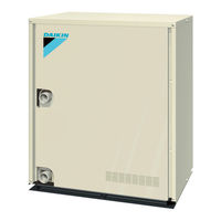
Daikin RWEYQ84MTJU Service Manual (312 pages)
Water Cooled Inverter Series Heat Pump Heat Recovery-60Hz R-410A
Brand:
Daikin
| Category:
Heat Pump
| Size: 14 MB
Table of Contents
Table of Contents
2
Introduction
8
Safety Cautions
8
Preface
12
Part 1 General Information
14
Features
15
Design Flexibility
16
Easy Installation
18
Energy Saving
19
Enhanced Usability
20
Outside Unit Lineup
21
Model Names
22
Water Cooled System
22
External Appearance
23
Indoor Units
23
Outside Units
24
Combination of Outside Units
25
Capacity Range
26
Part 2 Specifications
28
Outside Units
29
BS Units
36
Indoor Units
37
Ceiling Suspended Type
44
Floor Standing Type
47
Part 3 Refrigerant Circuit
50
Refrigerant Circuit
51
Rweyq60Mtju / Rweyq72Mtju / Rweyq84Mtju
51
Refrigerant Circuit Part
51
Bsvq36, 60M
53
Functional Parts Layout
54
Rweyq60Mtju / Rweyq72Mtju / Rweyq84Mtju
54
Front View
55
Refrigerant Flow for each Operation Mode
56
In Case of Heat Pump Connection
56
In Case of Heat Recovery Connection (One Outside Unit Installation)
58
In Case of Heat Recovery Connection (3 Outside Units Connection.)
62
In Case of Heat Recovery Connection
62
(3 Outside Units Connection.)
62
Part 4 Function
66
Function General
68
Symbol
68
Operation Mode
69
Normal Operation
70
BS Unit & Indoor Unit Operation Mode Detail
71
Stop
72
Stopping Operation
72
Standby
74
Restart Standby
74
Crankcase Heater Control
74
Startup Control
75
Cooling Start-Up Control
75
Heating Start-Up Control
76
Pressure Equalizing Control
77
Normal Control
78
Compressor Control
78
Unit Installation
79
Electronic Expansion Valve Control
80
Heat Exchange Mode in Heating Operation or Simultaneous Cooling / Heating Operation
81
Protection Control
83
High Pressure Protection Control
83
Low Pressure Protection Control
84
Discharge Pipe Protection Control
86
Inverter Protection Control
87
Cooling Fan Control
88
Special Operation
89
Oil Return Operation
89
Oil Return Operation of Water Heat Exchanger
91
Pump-Down Residual Operation Control
92
Refrigerant Drift Prevention
94
Other Control
95
Outside Unit Rotation
95
Outline of Control (Indoor Unit)
96
Drain Pump Control
96
Louver Control for Preventing Ceiling Dirt
98
Thermostat Sensor in Remote Controller
99
Thermostat Control While in Normal Operation
101
Thermostat Control in Dry Operation
101
Electronic Expansion Valve Control
102
Hot Start Control (in Heating Operation Only)
102
Heater Control
103
List of Swing Flap Operations
104
Freeze Prevention
105
Part 5 Test Operation
106
Test Operation
107
Procedure and Outline
107
Check Operation
109
Outside Unit PC Board Layout
111
Field Setting
112
Field Setting from Remote Controller
112
Simplified Remote Controller
114
Detailed Explanation of Setting Modes
116
External On/Off Input
117
Brc7C Type
120
Contents of Control Modes
121
Field Setting from Outside Unit
123
Image of Operation in the Case of a
140
Image of Operation in the Case of B
140
Emergency Operation
148
Part 6 Troubleshooting
150
Troubleshooting by Remote Controller
153
The INSPECTION / TEST Button
153
Self-Diagnosis by Wired Remote Controller
154
Self-Diagnosis by Wireless Remote Controller
155
Operation of the Remote Controller's Inspection / Test Operation Button
157
Remote Controller Service Mode
158
Remote Controller Self-Diagnosis Function
160
Malfunction Code Indication by Outdoor Unit Pcb
163
Troubleshooting by Indication on the Remote Controller
167
A0" Indoor Unit: Error of External Protection Device
167
A1" Indoor Unit: PC Board Defect
168
PC Board Defect
168
A3" Indoor Unit: Malfunction of Drain Level Control System (S1L)
169
Troubleshooting
170
A6" Indoor Unit: Fan Motor (M1F) Lock, Overload
171
A7" Indoor Unit: Malfunction of Swing Flap Motor (MA)
175
A9" Indoor Unit: Malfunction of Moving Part of
177
Electronic Expansion Valve (Y1E)
177
AF" Indoor Unit: Drain Level above Limit
179
AJ" Indoor Unit: Malfunction of Capacity Determination Device
180
C4" Indoor Unit: Malfunction of Thermistor (R2T) for
181
Heat Exchanger
181
Malfunction of Thermistor (R3T) for Gas Pipes
182
C5" Indoor Unit: Malfunction of Thermistor (R3T) for Gas Pipes
182
C9" Indoor Unit: Malfunction of Thermistor (R1T) for Suction Air
183
CJ" Indoor Unit Remote Controller
184
CJ" Indoor Unit: Malfunction of Thermostat Sensor in
184
Remote Controller
184
PC Board Defect
185
E1" Outside Unit: PC Board Defect
185
E3" Outside Unit
186
Actuation of High Pressure Switch
186
E3" Outside Unit: Actuation of High Pressure Switch
186
E4" Outside Unit: Actuation of Low Pressure Sensor
188
Actuation of Low Pressure Sensor
188
Compressor Motor Lock
190
E5" Compressor Motor Lock
190
E9" Outside Unit
192
Electronic Expansion Valve (Y1E, Y3E)
192
F3" Outside Unit: Abnormal Discharge Pipe Temperature
194
Abnormal Discharge Pipe Temperature
194
Refrigerant Overcharged
195
F6" Refrigerant Overcharged
195
HJ" Malfunction of Water System
197
J3" Outside Unit
199
Malfunction of Discharge Pipe Thermistor (R3T)
199
J3" Outside Unit: Malfunction of Discharge Pipe Thermistor (R3T)
199
J4" Malfunction of Heat Exchanger Gas Pipe Thermistor (R4T)
200
J5" Outside Unit
201
J5" Outside Unit: Malfunction of Thermistor (R2T) for Suction Pipe
201
Malfunction of Thermistor (R2T) for
201
Malfunction of Liquid Pipe Thermistor (R6T)
202
J7" Malfunction of Liquid Pipe Thermistor (R6T)
202
J9" Malfunction of Sub Cooling Heat Exchanger Outlet Thermistor (R5T)
203
JA" Outside Unit: Malfunction of Discharge Pipe Pressure Sensor
204
JC" Outside Unit: Malfunction of Suction Pipe Pressure Sensor
206
Malfunction of PC Board
208
L1" Outdoor Unit: Malfunction of PC Board
208
L4" Outside Unit: Malfunction of Inverter Radiating Fin
209
Temperature Rise (R1T)
209
L5" Outside Unit: Inverter Compressor Abnormal
210
Inverter Compressor Abnormal
210
L8" Outside Unit: Inverter Current Abnormal
211
L9" Outside Unit: Inverter Start up Error
213
Inverter Start up Error
213
Inverter and Control PC Board
214
LC" Outside Unit: Malfunction of Transmission between
214
Inverter Over-Ripple Protection
216
P1" Outside Unit: Inverter Over-Ripple Protection
216
P4" Outside Unit: Malfunction of Inverter Radiating Fin
218
Temperature Sensor
218
Faulty Combination of PC Board
219
UO" Low Pressure Drop Due to Refrigerant Shortage or
220
Electronic Expansion Valve Failure
220
Reverse Phase, Open Phase
222
U1" Reverse Phase, Open Phase
222
Power Supply Insufficient or Instantaneous Failure
223
U2" Power Supply Insufficient or Instantaneous Failure
223
Check Operation Not Executed
225
U3" Check Operation Not Executed
225
U4" Malfunction of Transmission between Indoor Units
226
U5" Malfunction of Transmission between Remote Controller and Indoor Unit
228
Indoor Unit
228
U7" Malfunction of Transmission between Outside Units
229
U8" Malfunction of Transmission between Master and
231
Slave Remote Controllers
231
U9" Malfunction of Transmission between Indoor and Outside Units in the same System
232
UA" Indoor & Outside Units and Remote Controller
234
Combination Failure
234
UC" Address Duplication of Centralized Controller
236
UE" Malfunction of Transmission between Centralized Controller and Indoor Unit
237
UF" Refrigerant System Not Set, Incompatible Wiring/Piping
239
UH" Malfunction of System, Refrigerant System Address Undefined
240
Troubleshooting (OP: Central Remote Controller)
242
PC Board Defect
242
M1" PC Board Defect
242
M8" Malfunction of Transmission between Optional Controllers for Centralized Control
243
Improper Combination of Optional Controllerslers for Centralized Controllers
245
Centralized Control
245
Address Duplication, Improper Setting
247
MC" Address Duplication, Improper Setting
247
Troubleshooting (OP: Schedule Timer)
248
Malfunction of Transmission between Centralized Controller and Indoor Unit
248
Indoor Unit
248
PC Board Defect
250
M1" PC Board Defect
250
M8" Malfunction of Transmission between Optional Controllers for Centralized Control
251
Improper Combination of Optional Controllerslers for Centralized Controllers
253
Centralized Control
253
MC" Address Duplication, Improper Setting
255
Troubleshooting (OP: Unified ON/OFF Controller)
256
Operation Lamp Blinks
256
Display "Under Host Computer Integrate Control" Blinks (Repeats Single Blink)
258
Display "Under Host Computer Integrate Control" Blinks (Repeats Double Blink)
261
Part 7 Procedure for Mounting
268
Dismounting of Switch Box
268
Procedure for Mounting / Dismounting of Switch Box
269
Procedure for Dismounting
269
Procedure for Mounting
269
Part 8 Appendix
272
Piping Diagrams
273
Outside Units
273
Indoor Unit
274
BS Unit
276
Wiring Diagrams
277
Outside Unit
277
Outside Unit Field Wiring
278
Indoor Unit
280
BS Unit
284
List of Electrical and Functional Parts
285
Outside Unit
285
Indoor Side
286
Option List
289
Optional Accessories
289
Thermistor Resistance / Temperature Characteristics
291
Pressure Sensor
293
Method of Replacing the Inverter's Power Transistors and Diode Modules
294
Part 9 Precautions for New Refrigerant (R-410A)
296
Precautions for New Refrigerant (R-410A)
297
Outline
297
Service Tools
299
Malfunction of Capacity Determination Device
307
Advertisement
Advertisement
Related Products
Daikin VRV-WIII RWEYQ84PYDN
Daikin VRV-WIII RWEYQ84PTJU9
Daikin RWEYQ60MTJU
Daikin RWEYQ168MTJU
Daikin RWEYQ216MTJU
Daikin RWEYQ252MTJU
Daikin VRV-WII RWEYQ-MY1 Series
Daikin VRV-WIII RWEYQ72PYDN
Daikin VRV-WIII RWEYQ144PYDN
Daikin VRV-WIII RWEYQ216PYDN
Daikin Categories
Air Conditioner
Heat Pump
Remote Control
Chiller
Fan
More Daikin Manuals
Login
Sign In
OR
Sign in with Facebook
Sign in with Google
Upload manual
Upload from disk
Upload from URL