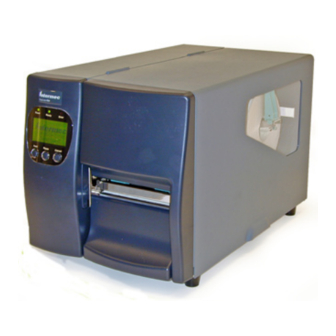
Intermec EasyCoder PD4 Service Manual
Bar code label printer
Hide thumbs
Also See for EasyCoder PD4:
- Programmer's reference manual (162 pages) ,
- User manual (100 pages) ,
- Installation instructions manual (12 pages)
Table of Contents
Advertisement
Advertisement
Table of Contents
Troubleshooting

Related Manuals for Intermec EasyCoder PD4


Summary of Contents for Intermec EasyCoder PD4
- Page 1 Service Manual EasyCoder PD4 Bar Code Label Printer...
- Page 2 The information contained herein is proprietary and is provided solely for the purpose of allowing customers to operate and service Intermec-manufactured equipment and is not to be released, repro- duced, or used for any other purpose without written permission of Intermec.
- Page 3 EN50081-1 (EN55022 CLASS A) and EN61000-4-2/-3/-4/-5/- 6/-8/-11 (IEC Teil 2,3,4). The equipment also tested and passed in accordance with the European Standard EN55022 for the both Radiated and Conducted emissions limits. Intermec EasyCoder PD4—Service Manual...
- Page 4 Intermec EasyCoder PD4—Service Manual...
-
Page 5: Table Of Contents
Ribbon Module Belt ....................29 Ribbon Supply and Rewind Units ................30 Ribbon Out Sensor ....................31 Ink Position Knob ....................32 Print Mechanism Print Unit ........................34 Motor, Pulleys, and Belts ..................35 Platen Module ......................37 Media Guides ......................38 Label Gap Sensor Module ..................39 Intermec EasyCoder PD4—Service Manual... - Page 6 14.3 No Reaction at Power Up ..................93 14.4 Error During Printing ..................... 95 14.5 No Printing ......................96 14.6 Printing Partly Missing along the Feed Direction ............ 97 14.7 Printout not in Desired Position ................98 Firmware Upgrading Requirements........................102 Instructions ........................102 Intermec EasyCoder PD4—Service Manual...
-
Page 7: Before You Begin
Safety Summary Your safety is extremely important. Read and follow all warnings and cau- tions in this document before handling and operating Intermec equipment. You can be seriously injured, and equipment and data can be damaged if you do not follow the safety warnings and cautions. -
Page 8: Safety Icons
(ESD). When you see this icon, you must follow standard ESD guide- lines to avoid damaging the equipment you are servicing. Note: Notes either provide extra information about a topic or contain spe- cial instructions for handling a particular condition or set of circumstances. viii Intermec EasyCoder PD4—Service Manual... -
Page 9: Global Services And Support
Service & Support. The Intermec Global Sales & Service page appears. From the Service & Support menu, move your pointer over Support, and then click Warranty. Web Support Visit the Intermec web site at http://www.intermec.com... -
Page 10: About This Manual
About This Manual This Service Manual is intended to facilitate installation, troubleshooting and repair of the Intermec EasyCoder PD4 printers in the versions deliv- ered at the date of publishing. Thus, all information on the Intermec ESim fi rmware is based on version 5.00. The on-going product improvement can be followed in the Printer Technical Bulletins from Intermec. -
Page 11: Models And Options
Models and Options This chapter describes the various models of the EasyCoder PD4 printer family, describes the option, and provides technical specifi cations. Intermec EasyCoder PD4—Service Manual... -
Page 12: Models
Chapter 1—Models and Options 1.1 Models The EasyCoder PD4 comes in three main models: • Printer without display and 200 dpi printhead density • Printer with display and 200 dpi printhead density • Printer with display and 300 dpi printhead density... -
Page 13: Options
Chapter 1—Models and Options 1.2 Options The options for the EasyCoder PD4 depend on the printer model: • External Keyboard/Display Unit (all models) • EasyLAN 10 External Ethernet Adapter (all models) • Memory Expansion Board 2MB (display models only) • Cutter (display models only) •... - Page 14 Chapter 1—Models and Options EasyCoder PD4 with cutter EasyCoder PD4 with rewinder (right-hand door not shown) Intermec EasyCoder PD4—Service Manual...
-
Page 15: Technical Specifi Cations
Chinese Big5 level 1 & 2 Korean KS X 11001:1992 Japanese JIS X0208:12977 Built-in bar code symbologies (stan- dard) Physical Measures Dimensions (W × L × H) 276 × 454.6 × 283.0 mm (10.85 × 17.9 × 11.2 in) Intermec EasyCoder PD4—Service Manual... - Page 16 Accessories and Options Integral Self-strip Unit with Liner Option For peel-off operation Takeup Cutter Option 2MB Flash Memory Expansion Card Option Keyboard/Display Unit Option EasyLAN 10 External Ethernet Option Adapter /. Models with graphic display front panel only. Intermec EasyCoder PD4—Service Manual...
-
Page 17: Front Panels
Front Panels This chapter describes the front panels for various models of the Easy- Coder PD4 printer family. Intermec EasyCoder PD4—Service Manual... -
Page 18: Front Panel (No Display)
2.1 Front Panel (no display) Description The displayless model of the EasyCoder PD4 has a front panel moulding with three colored LED control lamps and three control keys. The control lamp LEDs are fi tted on a console pcb which also contains the switches for the control keys and a buzzer. -
Page 19: Front Panel (With Display)
Chapter 2—Front Panels 2.2 Front Panel (with display) Description The display-equipped models of the EasyCoder PD4 have a front panel moulding with three colored LED control lamps, three control keys, and a large graphic LCD display. The control lamp LEDs are fi tted on a console pcb which also contains the LCD display, the switches for the control keys and a buzzer. -
Page 20: Replacing The Front Panel
4 Lift the front panel assembly up/out so the panel moulding disengages the two keyholes in the center section. 5 In case of a EasyCoder PD4 with display, disconnect the strip module cable from CN12 on the main board and remove it from the clips, ties, and plastic spiral binding. -
Page 21: Bottom Right-Hand Panel
(self-strip) operation in connection with an optional rewinder (see Chapter 8). It must be permanently removed before installing an optional cutter, see Chapter 10. The panel is held by a knurled screw inserted from beneath the bottom plate. Intermec EasyCoder PD4—Service Manual... -
Page 22: Console Pcb
Chapter 2—Front Panels 2.5 Console pcb. Components R3 R11 R35 R10 R22 R17 R6 R1 C6 R20 LS08 C8 C9 C10 C11 C12 C13 C14 LS32 200−000103−02 HC14 C4 R14 R15 R38 Intermec EasyCoder PD4—Service Manual... - Page 23 Chapter 2—Front Panels Schematics Intermec EasyCoder PD4—Service Manual...
- Page 24 Chapter 2—Front Panels Intermec EasyCoder PD4—Service Manual...
-
Page 25: Side Panels
Side Panels This chapter describes the right-hand door assembly that covers the media compartment and the left-hand side panel that covers the electronics com- partment. Intermec EasyCoder PD4—Service Manual... -
Page 26: Right-Hand Door
4 screws (not included). The top/right panel can be replaced separately and is attached to the door using a total of four screws (not included). Window Label Right-hand door Top/right panel Intermec EasyCoder PD4—Service Manual... -
Page 27: Left-Hand Panel
The left-hand panel covers the electronics compartment. It is a one-piece metal panel which is fi tted to the center section using two screws and to the rear plate and the bottom plate using series of leaf springs along the edges. Screw Leaf-springs Screw Panel Leaf-springs Intermec EasyCoder PD4—Service Manual... - Page 28 Check that the leaf springs along the bottom edge fi t the bottom plate. 2 Open the right-hand door. 3 Secure the panel using two screws inserted from the media compart- ment. 4 Reconnect the power cord. Intermec EasyCoder PD4—Service Manual...
-
Page 29: Chassis
Chassis This chapter describes chassis, which consists of the center section, the bottom plate, and the rear plate. Intermec EasyCoder PD4—Service Manual... -
Page 30: Print Mechanism
• Center section (two different; the displayless model has no hole for the rewinder and no cover plate) • Rear plate Rear plate Center section Rewinder cover plate (display model only) Dampeners (x2) Rubber feet (x4) Bottom plate Intermec EasyCoder PD4—Service Manual... -
Page 31: Rear Plate
It also has slots for the parallel interface connector and the USB connector, which are fi tted on the main board. Serial port USB port Parallel port On/Off switch AC power cord socket Slot for external Label media supply Intermec EasyCoder PD4—Service Manual... - Page 32 Chapter 4—Chassis Serial port connector (cable not shown) Power switch kit (cables not shown) Intermec EasyCoder PD4—Service Manual...
-
Page 33: Media Supply
Media Supply This chapter describes the media supply post with its two types of edge guide. Intermec EasyCoder PD4—Service Manual... -
Page 34: Media Supply Post
Short edge guide Tall edge guide (exploded) Screws (x3) Hook Washer Spring Post Screws (x3) Guide plate Center section Intermec EasyCoder PD4—Service Manual... - Page 35 fi t different media widths. Edge guide Hook Washer Coil spring Post Be careful to fl ip the high edge guide straight up before closing the side door, or the guide could be damaged. Intermec EasyCoder PD4—Service Manual...
- Page 36 Chapter 5—Media Supply Intermec EasyCoder PD4—Service Manual...
-
Page 37: Transfer Ribbon Mechanism
Transfer Ribbon Mechanism This chapter describes the thermal transfer ribbon mechanism. Intermec EasyCoder PD4—Service Manual... -
Page 38: Ribbon Module
5 Tilt the ribbon module so you can remove the belt from the pulley on the platen roller shaft. 6 Do not dismantle the module any further, unless you need to replace the belt (See Chapter 6.2). Reassemble in reverse order Intermec EasyCoder PD4—Service Manual... -
Page 39: Ribbon Module Belt
5 Remove the belt from the pulley on the rewind unit. Make sure that the spring and washer stay on the supply unit shaft. 6 Reassemble in reverse order Screws (x4) Bearing Washer Spring Bracket E-ring One-way clutch E-ring Washer Belt Intermec EasyCoder PD4—Service Manual... -
Page 40: Ribbon Supply And Rewind Units
If the printer have problems pulling the labels (especially when using a ribbon less than 50 mm/2 in wide), push the knob on the ribbon supply hub inwards (1) and rotate it counterclockwise to decrease the breaking force (2). Intermec EasyCoder PD4—Service Manual... -
Page 41: Ribbon Out Sensor
5 Pull out the sensor and the isolating sheet. 6 Install the replacement sensor in reverse order. Do not forget to fi t the isolating sheet between the sensor and the center section. Cable (connector not shown) Screw Washer Sensor assy. Isolating sheet Intermec EasyCoder PD4—Service Manual... -
Page 42: Ink Position Knob
4 Install the ink position knob in reverse order. Do not forget to move it to either end of the slot before closing the right-hand door. Ink position knob Slot Spring Intermec EasyCoder PD4—Service Manual... -
Page 43: Print Mechanism
Print Mechanism This chapter describes the print mechanism and the stepper motor that drives both the platen roller and the transfer ribbon takeup unit. Intermec EasyCoder PD4—Service Manual... -
Page 44: Print Unit
Other parts are not stocked. Printhead module 203.2 or 300 dpi) Label gap sensor module (Pulley; Headlift sensor for belt to ribbon unit) Pulley (motor belt; 203.2 or 300 dpi) Media guide Media guide Platen module Intermec EasyCoder PD4—Service Manual... -
Page 45: Motor, Pulleys, And Belts
The stepper motor module is attached to the bottom plate using four screws. The motor is connected by a four-wire cable harness to connector CN7 on the main board. Belt Motor Pulley Intermec EasyCoder PD4—Service Manual... - Page 46 3 Remove the E-ring that holds the pulley on the platen roller shaft. 4 Install the pulley in reverse order. Make sure the pulley is intended for the type of printhead (203.2 or 300 dpi) installed in the printer. Intermec EasyCoder PD4—Service Manual...
-
Page 47: Platen Module
5 Remove the E-rings and washers from either end of the platen roller shaft. 6 Remove the bearings. 7 Pull out the platen roller. 8 Install the platen roller, bearings, washers, E-rings, pulleys, and front panel in reverse order. Intermec EasyCoder PD4—Service Manual... -
Page 48: Media Guides
The media guides are pressed onto their respective shafts and can easily be removed and installed by hand. Take care to fi t the guides as illustrated below, that is, the fl at side should face the media. Inner gable Shafts Inner media guide Outer media guide Intermec EasyCoder PD4—Service Manual... -
Page 49: Label Gap Sensor Module
Sensitivity The sensitivity of the sensor can be adjusted in the Setup Mode (printers with display only) or using ESim commands, see the EasyCoder PD4 User’s Guide and the Intermec ESim v5.xx, Programmer’s Reference Manual. Intermec EasyCoder PD4—Service Manual... - Page 50 8 Do not dismantle the module. The entire module is available as a replacement part. 9 Install the label gap sensor module in reverse order. Label gap sensor module Outer gable Bearing Washer E-ring Screw (x6) Intermec EasyCoder PD4—Service Manual...
-
Page 51: Headlift Sensor
7 Pull out the headlift sensor through the holes in the bracket and the inner gable and into the electronics compartment. 8 Install the headlift sensor in reverse order. Bearing Washer Headlift sensor E-ring Screw (x6) Outer gable Intermec EasyCoder PD4—Service Manual... -
Page 52: Printhead Module
Information on how to switch between direct thermal and thermal transfer printing is provided in the User’s Guide. The EasyCoder PD4 comes with two printhead densities, 203.2 dpi (8 dots/mm) and 300 dpi (11.81 dots/mm). The 300 dpi printhead is only available for printer models with displays. - Page 53 1 Open the top cover. 2 Remove the ribbon. 3 Lift the printhead by pulling out the printhead lever and fl ipping it counterclockwise a quarter of a turn. Intermec EasyCoder PD4—Service Manual...
- Page 54 To perform this adjustment, follow all the steps below: 1 Open the top cover. 2 Remove the ribbon. 3 Important step! Use a straight-slot screwdriver to turn the two screws at the top of the printhead bracket counterclockwise a single turn. Intermec EasyCoder PD4—Service Manual...
- Page 55 7 Load the ribbon (only in case of thermal transfer printing). 8 Test the print quality and readjust if necessary. (Hint! If you use direct thermal media you will not have to load and remove the ribbon over and over again.) Intermec EasyCoder PD4—Service Manual...
- Page 56 5 Pull out the printhead straight forward. 6 Insert the replacement printhead so it engages the connectors on the printhead bracket. 7 Reload the transfer ribbon, close the printhead, close the side door and switch on the power. Intermec EasyCoder PD4—Service Manual...
- Page 57 • When using preprinted labels or labels with some type of varnish or non-standard top coating for direct thermal printing, use original Intermec labels or inks recommended by leading manufacturers of direct thermal media. The labels must not contain any aggressive substances such as chloride or grinding substances such as titanium dioxide.
- Page 58 Chapter 7—Print Mechanism Intermec EasyCoder PD4—Service Manual...
-
Page 59: Rewinder Module
Rewinder Module This chapter describes the optional internal liner rewinder required for peel-off (self-strip) operation. The rewinder can only be fi tted on Easy- Coder PD4 printers with a display. Intermec EasyCoder PD4—Service Manual... - Page 60 8.1 Rewinder Module Description The rewinder module is an optional device for EasyCoder PD4 printer models with display. These printers are prepared with belt, pulley, and gear train for driving the rewinder using the same stepper motor that also drives the platen roller and transfer ribbon rewinder.
- Page 61 2 Open the side door and remove the rewinder option cover plate, which is held by two screws. Cover plate 3 Remove the U-shaped clip and attach the rewinder unit to the center section using the four screws included in the kit. Intermec EasyCoder PD4—Service Manual...
- Page 62 4 Plug in the cable from the rewinder switch into the front one of the two connectors in the center section. Switch Rewinder cable 5 Install the media as described in the EasyCoder PD4, User‘s Guide. Intermec EasyCoder PD4—Service Manual...
-
Page 63: Strip Module
Strip Module This chapter describes the strip module (also called “label taken sensor”) which is a standard feature on EasyCoder PD4 printers with a display. It cannot be fi tted on printers without a display. Intermec EasyCoder PD4—Service Manual... -
Page 64: Cutter
The strip module (also called “label taken sensor”) is a standard feature on all EasyCoder PD4 printers that have a LCD display. It cannot be fi tted on the model without display, where it is replaced by a similar plastic mould- ing without any sensor. - Page 65 5 Remove the E-ring that holds the strip module and pull it away. The strip module is only available as a complete unit. 6 Assemble in reverse order. E-ring Strip module Front panel Intermec EasyCoder PD4—Service Manual...
- Page 66 Chapter 9—Strip Module Intermec EasyCoder PD4—Service Manual...
- Page 67 Cutter This chapter describes the cutter which is an option for EasyCoder PD4 printers with a display. It cannot be fi tted on printers without a display. Never use the cutter to cut through any kind of adhesive, which will get stuck on the shears and render the cutter inoperable or even damage it.
-
Page 68: Cutter
The cutter cuts off portions of continuous media after printing and collects them on a tray. It is an option for EasyCoder PD4 printers with an LCD display, but cannot be used on printer models without a display. When a cutter is installed, the strip module (see Chapter 9) cannot be used. - Page 69 2 Open the side door and remove the tear bar, which is held by two Phil- lips screws. Screws Tear bar 3 Attach the cutter mechanism to the printer using the two Phillips screws and washers included in the kit. Intermec EasyCoder PD4—Service Manual...
- Page 70 6 If needed, fi t the tray to the front of the cutter. Intermec EasyCoder PD4—Service Manual...
- Page 71 3 After the media jam is cleared, switch on the power to the printer, and the cutter blade will go back to its original position. Note: It is recommended to use labels with a length of 35 mm (1.5 in) or more. Intermec EasyCoder PD4—Service Manual...
- Page 72 Chapter 10—Cutter Intermec EasyCoder PD4—Service Manual...
-
Page 73: Switching Power Module
Switching Power Module This chapter describes the switching power module and its connections from the power switch unit and to the main board. Intermec EasyCoder PD4—Service Manual... - Page 74 Do not attempt to repair the power module or replace the fuse a second time, but replace the entire unit. Fuse 5A slow 90-260 VAC In 24 VDC to main board Intermec EasyCoder PD4—Service Manual...
- Page 75 3 Remove the two screws at the front of the power module that hold it to the bottom plate. 4 Push the module forward so as to disengage the tab at the rear and lift out the entire unit. 5 Install the power module in reverse order. Intermec EasyCoder PD4—Service Manual...
- Page 76 CN4 FAN MADE IN TAIWAN − − AUTEC UPS 110−1001 REV−B SCR1 CONT1 F1 5A−250V Schematics VDR1 − CONT1 Q1+HS1 +24V D3+HS2 SCR1 + C11 + C12 + C13 + C14 7 6 5 4 +24V Intermec EasyCoder PD4—Service Manual...
-
Page 77: Main Board
Main Board This chapter describes the three different main boards including connec- tions, test points, component placement, and schematics. Intermec EasyCoder PD4—Service Manual... -
Page 78: Description
Chapter 12—Main Board 12.1 Description Models There are three different main boards for the EasyCoder PD4 depending on printer model: • EasyCoder PD4 No display 203.2 dpi • EasyCoder PD4 LCD display 203.2 dpi • EasyCoder PD4 LCD display 300 dpi The printer must be fi... -
Page 79: Replacement
4 Remove the fi ve screws and washers that hold the main board. (In case of a memory expansion board, there are four sets of screws and washers plus one hexagonal spacer.) 5 Install the main board in reverse order. Intermec EasyCoder PD4—Service Manual... -
Page 80: Connections
Chapter 12—Main Board 12.3 Connections EasyCoder PD4, no display, 203.2 dpi CN23 CN11 CN14 RS-232 Ribbon out Headlift Black mark through CN21 CNA1 & CNB1 CN28 Centronics Motor Printhead Power Intermec EasyCoder PD4—Service Manual... - Page 81 Chapter 12—Main Board EasyCoder PD4, display, 203.2 dpi CN23 CN11 CN12 CN17 CN14 CN22 RS-232 Ribbon out Strip module Rewinder full Headlift Black LCD Panel mark through CN21 CN3 & CN4 CN19 CNA1 & CNB1 CN28 Centronics Memory Cutter Motor...
- Page 82 Chapter 12—Main Board EasyCoder PD4, display, 300 dpi CN23 CN11 CN12 CN17 CN14 CN22 RS-232 Ribbon out Strip module Rewinder full Headlift Black LCD Panel mark through CN21 CN3 & CN4 CN19 CN28 Centronics Memory Cutter Motor Printhead Power expansion card...
-
Page 83: Components
D35 D37 D30 D26 D29 D25 D21 D15 D20 D14 D41 D38 D19 D42 R175 C115 C136 C145 C144 R171 R164 C146 R168 R169 R170 C147 R165 R172 C151 C137 C135 UART1 C154 CN23 R174 U43 C149 Intermec EasyCoder PD4—Service Manual... -
Page 84: Test Points
U28 Pin 15 Potentiometer reset POT_CK U28 Pin 14 Potentiometer serial clock POT_DI U28 Pin 12 Potentiometer serial data in TXD0 U27 Pin 11 RS-232 Port transmit data RXD0 U27 Pin 12 RS-232 Port receive data Intermec EasyCoder PD4—Service Manual... -
Page 85: Schematics
P155 P133 P154 P54/HLDA-/ALE P153 P55/HOLD- P152 P56/ALE/RAS- P151 P57/RDY- P134 P150 P135 P136 P107/AN7/KI3 P137 P106/AN6/KI2 P60/CTS0-/RTS0- P105/AN5/KI1 P61/CLK0 P104/AN4/KI0 P62/RxD0 P103/AN3 P63/TxD0 P102/AN2 P64/CTS1-/RTS1-/CTS0-/CLKS1 P101/AN1 P65/CLK1 AVss P100/AN0 P66/RxD1 Vref AVcc P67/TxD1 P97/ADtrg-/RxD4/SCL4/STxD4 P70/TxD2/SDA2/TA0out Intermec EasyCoder PD4—Service Manual... - Page 86 Chapter 12—Main Board Motor Driver MOTOR MOTOR Intermec EasyCoder PD4—Service Manual...
- Page 87 Chapter 12—Main Board Printhead Intermec EasyCoder PD4—Service Manual...
- Page 88 Chapter 12—Main Board Power Intermec EasyCoder PD4—Service Manual...
- Page 89 Chapter 12—Main Board Connectors STRIP MODULE HEADLIFT REWINDER BLACK MARK l u f COVER (not used) SEE THROUGH SPSTMP (not used) RIBBON REWIND (not used) FAN & MOTOR (not used) CUTTER CUTTER POWER TEMPERATURE SENSOR Intermec EasyCoder PD4—Service Manual...
- Page 90 Chapter 12—Main Board Ports 1 Intermec EasyCoder PD4—Service Manual...
- Page 91 Chapter 12—Main Board Ports 2 Intermec EasyCoder PD4—Service Manual...
- Page 92 Chapter 12—Main Board AVCC AGND Intermec EasyCoder PD4—Service Manual...
-
Page 93: Memory Expansion Card
Chapter 12—Main Board 12.7 Memory Expansion Card Description The memory expansion card can only be installed in EasyCoder PD4 printers with and LCD display. It provides an additional 2MB of fl ash memory. Installation To install a memory expansion card, follow these steps: 1 Remove the left side panel (see Chapter 3.2). - Page 94 Chapter 12—Main Board Intermec EasyCoder PD4—Service Manual...
-
Page 95: Interfaces
Interfaces This chapter describes the communication interfaces of the EasyCoder PD4: • RS-232 serial interface • USB serial interface • Centronics parallel interface Intermec EasyCoder PD4—Service Manual... -
Page 96: Serial Interface
The RS-232 serial interface is a bidirectional communication protocol for distances up to 10 to 15 metres (33 to 49 ft). The communication parameters can be set in the Setup Mode (see EasyCoder PD4, User’s Guide) or using a Y command (see ESim for EasyCoder PD4 v5.xx, Programmer’s... -
Page 97: Usb Serial Interface
13.2 USB Serial Interface Description The EasyCoder PD4 printer supports USB v1.1 (also called USB 2.0 full speed). To use the USB interface for printing from a PC, you need a special Intermec USB printer driver installed in your PC. -
Page 98: Centronics Parallel Interface
Data 0-7 host /Acknowledge printer Busy printer /Paper empty printer /Select printer 14-16 Not connected Chassis ground External +5 VDC Max 500mA, permanently enabled 19-30 Signal ground Not connected /ERROR printer Signal ground 34-36 Not connected Intermec EasyCoder PD4—Service Manual... -
Page 99: Troubleshooting
Troubleshooting This chapter describes how to troubleshoot the EasyCoder PD4 printer and suggests remedies, which in most cases means identifying a faulty part and replacing it. Do not attempt repairing the power supply or any circuit boards. Intermec EasyCoder PD4—Service Manual... -
Page 100: Error Handling
72: Flashing not completed (RESET) Switch power off/on or send ^@ cmd 73: Download error (RESET) Switch power off/on or send ^@ cmd 81: Cutter jammed or not installed Clear media from cutter or disable cutter Intermec EasyCoder PD4—Service Manual... -
Page 101: Troubleshooting Check List
Check label gap sensor for faults or bad connection Chapter 14.7 Check the edge guide and media guides Chapters 5.1 and Check the media Chapter 14.7 Check if the platen roller needs cleaning or replacement Chapter 7.3 Intermec EasyCoder PD4—Service Manual... - Page 102 Check if paper feed rods are sticky. Clean if necessary using isopropyl alcohol. When using stripper, abnormal func- Check if stripper full sensor is working Chapter 9.1 tion occurs Check if media is loaded properly User’s Guide Intermec EasyCoder PD4—Service Manual...
-
Page 103: No Reaction At Power Up
- Check 24 VDC output in the socket at the main board end of the cable (there are 3 red line wires and 3 black ground wires). If there is no +24V, the cable is damaged. Intermec EasyCoder PD4—Service Manual... - Page 104 • Faulty console unit. - Try connecting the cable to a replacement console board without actually installing it (mind the risk of electrostatic discharges). If the trouble seems to be the console board, replace the entire panel module. Intermec EasyCoder PD4—Service Manual...
-
Page 105: Error During Printing
- If so, clean using isopropyl alcohol or a cleaning card. • Check for bad settings or program command errors. - See the User’s Guide or the ESim v5.xx for EasyCoder PD4, Program- mer’s Reference Manual. Intermec EasyCoder PD4—Service Manual... -
Page 106: No Printing
• Label taken sensor active and label not removed. - Check if the label taken sensor is folded out and enabled and if there is a label left in the outfeed slot or the ambient light disturbs the label taken sensor. Intermec EasyCoder PD4—Service Manual... -
Page 107: Printing Partly Missing Along The Feed Direction
- If the printing is weak or non-existing on either the inner or outer part of the media, the printhead balance may need to be readjusted as described in Chapter 7.7. This is most likely to occur when switching between media of different widths. Intermec EasyCoder PD4—Service Manual... -
Page 108: Printout Not In Desired Position
- In case of self-adhesive labels on a liner, consider if the liner has insuf- fi cient transparency or if there is some kind of printing on the liner that may interfere with the label gap sensor. Intermec EasyCoder PD4—Service Manual... - Page 109 • Bad friction between platen roller and media. - Check if the platen roller is slippery, worn out, or dry and hard. Clean or replace if necessary (see Chapter 7.3). Intermec EasyCoder PD4—Service Manual...
- Page 110 Chapter 14—Troubleshooting Intermec EasyCoder PD4—Service Manual...
-
Page 111: Firmware Upgrading
Firmware Upgrading This appendix describes how to upgrade the printer with a new fi rmware version. Intermec EasyCoder PD4—Service Manual... -
Page 112: Requirements
To upgrade the printer’s fi rmware via a cable connection from a PC run- ning MS Windows, you will need the following: • The Intermec EasyCoder PD4 Confi g Tool. This is a free software running under Microsoft Windows . It makes it possible to download various fi... - Page 114 Intermec Technologies Corporation Corporate Headquarters 6001 36th Avenue West Everett, WA 98203 U.S.A. tel +425.348.2600 fax +425.355.9551 www.intermec.com Intermec EasyCoder PD4—Service Manual *1-960618-00* *1-960618-00*...