3Com V7122 User Manual
Hide thumbs
Also See for V7122:
- User manual (266 pages) ,
- Installation manual (58 pages) ,
- User manual manual (496 pages)

Related Manuals for 3Com V7122


Summary of Contents for 3Com V7122
- Page 1 V7122 Gateway User Guide System Release 5.0 http://www.3com.com Part Number 900-0484-01 Rev AA Published December 2007...
- Page 2 3Com Corporation, 350 Campus Drive, Marlborough MA 01752-3064 Copyright © 2007, 3Com Corporation. All rights reserved. No part of this documentation may be reproduced in any form or by any means or used to make any derivative work (such as translation, transformation, or adaptation) without written permission from 3Com Corporation.
-
Page 3: Table Of Contents
ONTENTS ONTENTS BOUT UIDE How to Use This Guide 15 Conventions 16 Model Numbers for the V7122 Gateways 16 Documentation Comments 17 Notices 18 WEEE EU Directive 18 Abbreviations and Terminology 18 1: O HAPTER VERVIEW V7122 Overview 19 TP-1610 Overview 20... - Page 4 Installing the V7122 41 Unpacking 42 Package Contents 42 Mounting the V7122 Gateway 43 Cabling the V7122 Gateway 45 Installing the TP-1610 51 Unpacking 52 Package Contents 52 Installing the TP-1610 52 Cabling the TP-1610 54 Installing the TP-260 54...
- Page 5 Software Upgrade Wizard 132 Auxiliary Files 137 Updating the Software Upgrade Key 139 Maintenance 139 Locking and Unlocking the Gateway 139 Saving Configuration 141 Resetting the Gateway 142 Logging Off the Embedded Web Server 143 Reader’s Notes 144 V7122 Gateway User Guide...
- Page 6 Upgrading the 244 Gateway 244 Vendor Specific Information Field 244 Reader’s Notes 246 8: T HAPTER ELEPHONY APABILITIES Working with Supplementary Services 247 Call Hold and Retrieve Features 247 Call Transfer 248 Configuring the DTMF Transport Types 248 V7122 GatewayUser Guide...
- Page 7 No-Op Packets 275 Point-to-Point Protocol over Ethernet (PPPoE) 275 Point-to-Point Protocol (PPP) Overview 275 PPPoE Overview 276 PPPoE in 3Com Gateways 277 IP Multicasting 278 Robust Reception of RTP Streams 278 Multiple Routers Support 278 Simple Network Time Protocol Support 279...
- Page 8 Dynamic Tables vs. Static Tables 302 Secret Tables 302 Using the ini File to Configure Parameter Tables 303 Customizing the V7122 Web Interface 305 Replacing the Main Corporate Logo 305 Replacing the Background Image File 307 Customizing the Product Name 309...
- Page 9 RADIUS Login Authentication 350 Setting Up a RADIUS Server 350 Configuring RADIUS Support 352 Internal Firewall 353 Network Port Usage 355 Recommended Practices 356 Legal Notice 357 Reader’s Notes 358 14: D HAPTER IAGNOSTICS Self-Testing 359 V7122 Gateway User Guide...
- Page 10 SNMP Manager Backward Compatibility 385 Dual Module Interface 385 SNMP NAT Traversal 386 SNMP Administrative State Control 386 Node Maintenance 386 Graceful Shutdown 387 3Com’s Element Management System 388 Reader’s Notes 389 16: C HAPTER ONFIGURATION ILES Configuring the Call Progress Tones 391...
- Page 11 Reader's Notes 419 D: T P/TFTP C PPENDIX ONFIGURATION TILITY When to Use the BootP/TFTP 420 An Overview of BootP 420 Key Features 421 Specifications 421 Installation 421 Loading the cmp File, Booting the Device 422 V7122 Gateway User Guide...
- Page 12 Encoding / Decoding an ini File 447 Creating a Loadable Prerecorded Tones File 448 PSTN Trace Utility 450 Operation 450 Reader’s Notes 453 H: R PPENDIX ELEASE EASON APPING Reason Header 454 Fixed Mapping of ISDN Release Reason to SIP Response 455 V7122 GatewayUser Guide...
- Page 13 FCC Statement 479 TP-1610 480 Safety Notice 481 Industry Canada Notice 481 Digital Device Warnings 481 Network Information and Intent of Use 482 Network Compatibility 482 Telecommunication Safety 482 FCC Statement 483 TP-260 484 Safety Notice 485 V7122 Gateway User Guide...
- Page 14 Industry Canada Notice 485 FCC Digital Device Warnings 486 Network Information and Intent of Use 486 Network Compatibility 486 Telecommunication Safety 486 FCC Statement 487 Reader’s Notes 487 L: O PPENDIX BTAINING UPPORT FOR RODUCT Customer Support 488 V7122 GatewayUser Guide...
-
Page 15: About This Guide
BOUT UIDE This document describes the release of the 3Com V7122 Digital SIP Gateway, TP-1610 SIP cPCI board, and TP-260 SIP PCI board. Information contained in this document is believed to be accurate and reliable at the time of printing. However, due to ongoing product improvements and revisions, 3Com cannot guarantee accuracy of printed material after the Date Published nor can it accept responsibility for errors or omissions. -
Page 16: Conventions
Information that alerts you to potential personal injury or death. Model Numbers for the V7122 Gateways ® This guide describes the operations for the following 3Com VCX™ Digital SIP Gateways: The VCX V7122 Digital Gateway 16 Span (3CRVG71224-07) The VCX V7122 Digital Gateway 8 Span (3CRVG71223-07) -
Page 17: About Thi Guide
Your name and organization (optional) Example: V7122 User Guide Part Number 900-0394-01 Page 25 See the Appendix Obtaining Support for Your Product in this guide for details on how to register your product and get support from 3Com. V7122 Gateway User Guide... -
Page 18: Notices
The gateway is supplied as a sealed unit and must only be serviced by qualified service personnel. Where ‘network’ appears in this guide, it means Local Area Network (LAN), Wide Area Network (WAN), and the like. accessed via the gateway’s Ethernet interface. V7122 GatewayUser Guide... -
Page 19: Chapter 1: Overview
V7122 Overview The V7122 SIP Voice over IP (VoIP) gateway enables voice, fax, and data traffic to be sent over the same IP network. The gateway provides excellent voice quality and optimized packet voice streaming over IP networks. -
Page 20: Tp-1610 Overview
Enabling accelerated design cycles with higher density and reduced costs, the TP-1610 is an ideal building block for scalable, reliable VoIP solutions. With the TP-1610’s comprehensive feature set, customers can quickly design a wide range of solutions for PSTN and VoIP networks. V7122 GatewayUser Guide... -
Page 21: Tp-260 Overview
SIP as a control protocol, the TP-260 enables System Integrators short time-to-market and reliable cost-effective deployment of next-generation networks. The TP-260 utilizes the TPM- 1100 PMC module, which is based on the VolPerfect™ architecture, 3Com' underlying core media gateway technology. -
Page 22: Sip Overview
SIP also provides a registration function that enables users to upload their current locations for use by proxy servers. SIP, on the gateway, complies with the IETF (Internet Engineering Task Force) RFC 3261 (see www.ietf.org/rfc/rfc3261.txt?number=3261). V7122 GatewayUser Guide... -
Page 23: Features
EMS for comprehensive management operations (FCAPS). Simple Network Management Protocol (SNMP) and Syslog support. SMDI support for Voice Mail applications (V7122 only). ThroughPacket™ proprietary feature that aggregates payloads from several channels into a single IP packet to reduce bandwidth overhead. -
Page 24: Pstn-To-Sip Interworking Features
Interworking of Calling and Called Subaddress values for SIP ISDN calls. Supports ISDN en-block or overlap dialing for incoming Tel IP calls. Supports a digit map pattern to reduce the dialing period when Overlap dialing is used. V7122 GatewayUser Guide... -
Page 25: Supported Sip Features
Single gateway Registration or multiple Registration of all gateway endpoints. Supported methods: INVITE, CANCEL, BYE, ACK, REGISTER, OPTIONS, INFO, REFER, UPDATE, NOTIFY, PRACK and SUBSCRIBE. Modifying connection parameters for an already established call (re-INVITE). Working with a Redirect server and handling 3xx responses. V7122 Gateway User Guide... - Page 26 Can negotiate coder from a list of given coders. Responds to OPTIONS messages both outside a SIP dialog and in mid-call. Generates SIP OPTIONS messages as Proxy keep-alive mechanism. Representing trunk groups in tel/sip Uniform Resource Identifiers (URIs) according to <draft-ietf-iptel-trunk-group-04>. V7122 GatewayUser Guide...
- Page 27 OPTIONS request. The gateway uses the X-Resource header in the following format: ‘X-Resource: telchs=100/240;mediachs=0/0’, Where ‘telchs’ specifies the number of free tel channels / total tel channels. For more updated information on the gateway’s supported features, see the latest V7122 Gateway Release Notes. V7122 Gateway User Guide...
- Page 28 V7122 GatewayUser Guide...
-
Page 29: Chapter 2: Physical Description
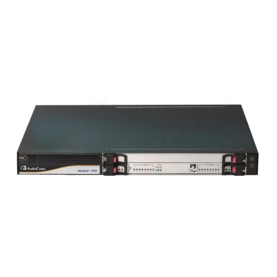
A single compactPCI™ TP-1610 board (see TP-1610 Physical Description). A single TP-1610 Rear Transition Module (RTM) (see Rear Transition Module). A single available cPCI slot for an optional third-party CPU board (see Optional CPU Board). V7122 Front View Figure 2 V7122 Gateway User Guide... -
Page 30: The V7122 Chassis
TP-1610 board in its front cage, slot #1 (the lower slot) and the TP-1610 RTM in its rear cage, slot #1 (the lower slot). Slot # 2 in the V7122 chassis’ front and rear cages can optionally be used by customers for a CPU board. -
Page 31: Optional Cpu Board
Power Supply The V7122 power supply is available in three configuration options: Single universal 100-240 VAC 1 A max, 50-60 Hz. Dual-redundant 100-240 VAC 1.5 A max, 50-60 Hz. -48 VDC power supply suitable for field wiring applications. Optional CPU Board The gateway provides an optional second cPCI slot that can be optionally used for customer’s CPU board. -
Page 32: Tp-1610 Front Panel Led Indicators
The functionality of the front panel LEDs for the TP-1610 is described in the following four tables and illustrated in Figure 3. Note that there is a choice of front panels according to the number of channels. V7122 GatewayUser Guide... - Page 33 1-span, 2-span, 4-span, and 8-span units. In the case of 1-span, 2- span and 4-span units, the extra LEDs are unused. Ethernet LED Indicators Table 7 Label LED Color LED Function LINK Green Link all OK Yellow Transmit / receive activity V7122 Gateway User Guide...
-
Page 34: Rear Transition Module
5) is required for a gateway equipped with 1, 2, 4, or 8 E1/T1 spans. The physical difference between the 1-Span, 2-Span and 4-Span RTMs, and the 8- span RTM is that the RJ-48c ports are depopulated correspondingly. Rear Panel with two 50-pin Connectors for 16 Trunks Figure 4 V7122 GatewayUser Guide... - Page 35 Figure 5 Rear Panel with 8 RJ-48c Connectors for 8 Trunks Component Descriptions Table 10 Item # Label Component Description ETHERNET 2 Ethernet Ports. 2 RJ-45 network connectors TRUNKS 8 E1/T-1 Spans. 8 RJ-48c trunk connectors V7122 Gateway User Guide...
-
Page 36: Tp-260 Physical Description
Pinout of the RJ-45 Connector Figure 7 RJ-45 LAN Connector and Pinout 1 2 3 4 5 6 7 8 1 = Tx+ 4, 5, 7, 8 2 = Tx- not connected 3 = Rx+ 6 = Rx- V7122 GatewayUser Guide... -
Page 37: Tp-260 Leds
Name Color Signal Description Link collision. The LED toggles when there is a collision in the half-duplex operation. Orange SPEED Link speed 10/100 Base-TX. The LED is ON for 100 Mbps and OFF for 10 Mbps. V7122 Gateway User Guide... - Page 38 OFF for half-duplex. Orange Link Transmit. When the PHY transmits, the LED toggles. RS-232 Internal use only. FAIL Indication from the TPM-1100. CLK40M When the LED toggles, the CLK40M for the PCI controller is active. V7122 GatewayUser Guide...
-
Page 39: Reader's Notes
Reader’s Notes V7122 Gateway User Guide... - Page 40 V7122 GatewayUser Guide...
-
Page 41: Chapter 3: Installation
Cable the V7122 (see Cabling the V7122). After powering-up the V7122, the Ready and LAN LEDs on the front panel turn to green (after a self-testing period of about 3 minutes). Any malfunction changes the Ready LED to red (see TP-1610 Front Panel LED Indicators for details on the V7122 LEDs). -
Page 42: Unpacking
Remove the gateway from the carton. Check that there is no equipment damage. Check, retain and process any documents. Notify 3Com or your local supplier of any damage or discrepancies Retain any diskettes or CDs. Package Contents Ensure that in addition to the gateway, the package contains: connection type) and one DC adaptor (screw connection type) connected to the rear panel of the gateway are supplied;... -
Page 43: Mounting The V7122 Gateway
Installing the V7122 Gateway in a 19-inch Rack Users can install the device in a standard 19-inch rack either by placing the device on a shelf preinstalled in the rack (preferred method), or by attaching the device directly to the rack’s... - Page 44 (of your choosing) in the vertical tracks of the 19-inch rack. Use standard 19-inch rack bolts (not provided) to fasten the device to the frame of the rack. 3Com recommends using two additional (not supplied) rear mounting brackets to provide added support. V7122 GatewayUser Guide...
-
Page 45: Cabling The V7122 Gateway
(Figure 12) configurations are illustrated here as representative products. V7122 Rear Panel Cabling (16 Trunks, Dual AC Power) Figure 11 V7122 Rear Panel Cabling (16 Trunks, Dual AC Power) Component Descriptions Table 15 Item # Label Component Description RTM locking screws. - Page 46 8 trunks. Protective earthing screw. 100-240~1.5A Dual AC power cables. V7122 Rear Panel Cabling (8 Trunks, DC Power)) Figure 12 V7122 Rear Panel Cabling (8 Trunks, DC Power) Component Descriptions Table 16 Item # Label Component Description RTM latches.
- Page 47 Connect the E1/T1 trunk interfaces (see Connecting the E1/T1 Trunk Interfaces). Install the Ethernet connection (see Installing the Ethernet Connection). Optionally, connect the V7122 RS-232 port to your PC (see Connecting the RS-232 Port to Your PC). Connect the power supply (see Connecting the Power Supply).
- Page 48 RS-232 port to either COM1 or COM2 RS-232 communication port on your PC. The required connector pinout and gender are shown in Figure 16. For information on establishing a serial communications link with the gateway, see Establishing a Serial Communications Link with the V7122. V7122 GatewayUser Guide...
- Page 49 Each of the dual power cables can be connected to different AC power phases. Connecting the DC Power Supply To connect the gateway to a DC power supply use one of these two options: DC Terminal block with a screw connection type. V7122 Gateway User Guide...
- Page 50 Connect the two insulated wires to the correct DC power supply. Ensure that the connections to the DC power supply maintain the correct polarity (see Figure 18). Insert the terminal block into the DC inlet located on the gateway. V7122 GatewayUser Guide...
-
Page 51: Installing The Tp-1610
Install the TP-1610 in your PC (see Installing the TP-1610). Cable the TP-1610 (see Cabling the TP-1610). When you have completed the above relevant sections you are then ready to start configuring the gateway ( C hapter 4: Getting Started). V7122 Gateway User Guide... -
Page 52: Unpacking
Remove the TP-1610 board from the carton. Check that there is no equipment damage. Check, retain and process any documents. Notify 3Com or your local supplier of any damage or discrepancies. Retain any diskettes or CDs. Package Contents Ensure that in addition to the TP-1610, the package contains:... - Page 53 Press the red ejector buttons on the two black ejector/injector latches on both ends and wait for the hot-swap blue LED to light, indicating that the board can be removed. Pull on the two ejector/injector latches and ease out the board from the slot. V7122 Gateway User Guide...
-
Page 54: Cabling The Tp-1610
Normal amounts of static electricity generated by clothing can damage electronic equipment. To reduce the risk of damage due to electrostatic discharge when installing or servicing electronic equipment, it is recommended that anti-static earthing straps and mats be used. V7122 GatewayUser Guide... -
Page 55: Unpacking
Remove the TP-260 board from the carton. Check that there is no equipment damage. Check, retain and process any documents. Notify 3Com or your local supplier of any damage or discrepancies. Retain any diskettes or CDs. Package Contents Ensure that in addition to the TP-260, the package contains:... -
Page 56: Cabling The
(labeled 5/8) on each splitter supports each of the last four trunks. The TP-260 E1/T1 cable splitter is part of the 8-span TP-260 product and is PSTN certified. When using a non-3Com E1/T1 cable splitter, 3Com cannot guarantee compliance with PSTN homologations. TP-260 E1/T1 Cable Splitter... - Page 57 Figure 7. Note that when assigning an IP address to the TP-260 using HTTP (under Step 1 in Assigning an IP Address Using HTTP), you may be required to disconnect this cable and re-cable it differently. V7122 Gateway User Guide...
-
Page 58: Reader's Notes
Reader’s Notes V7122 GatewayUser Guide... -
Page 59: Chapter 4: Getting Started
Parameters. Default Networking Parameters Table 18 Product Version Default Value V7122 and TP-1610 with a single module (up to 10.1.10.10 8 trunks) configuration, and TP-260 V7122 and TP-1610 with a double module (16 10.1.10.10 (trunks 1-8) and 10.1.10.11 (trunks 9-16) trunks) configuration Default subnet mask is 255.255.0.0, default gateway IP address is 0.0.0.0... -
Page 60: Assigning The An Ip Address To The Gateway
BootP/TFTP (Trivial File Transfer Protocol) configuration utility to access the device, ‘reflash’ the load and reset the password (see A ppendix D: The BootP/TFTP Configuration Utility for detailed information on using a BootP/TFTP configuration utility to access the device). V7122 GatewayUser Guide... -
Page 61: Assigning An Ip Address Using Bootp
When implementing a V7122 gateway with two modules, repeat Steps 3 to 5 for the second module; otherwise, skip to Step 7. Disconnect your PC from the gateway or from the hub / switch (depending on the connection method you used in Step Reconnect the gateway and your PC (if necessary) to the network. - Page 62 PC to connect to the Telnet interface over a secured connection. Login using the username (‘Admin’) and password (‘Admin’). To access the CLI using the RS-232 port: Connect the RS-232 port to your PC (For the V7122, see Connecting the RS-232 Port to Your...
-
Page 63: Configuring The Gateway's Basic Parameters
To configure the gateway’s basic parameters use the Embedded Web Server’s ‘Quick Setup’ screen (shown in Figure 20). See Accessing the Embedded Web Server for information on accessing the ‘Quick Setup’ screen. Quick Setup Screen Figure 20 V7122 Gateway User Guide... - Page 64 You are now ready to start using the gateway. To prevent unauthorized access to the gateway, it is recommended that you change the username and password that are used to access the Web Interface. See Configuring the Web User Accounts for details on how to change the username and password. V7122 GatewayUser Guide...
- Page 65 VoIP gateway configuration (ini file) and store it in a directory on your PC. This saved file can be used to restore configuration settings at a future time. For information on backing up and restoring the gateway’s configuration, see Restoring and Backing up the Gateway Configuration. V7122 Gateway User Guide...
-
Page 66: Reader's Notes
Reader’s Notes V7122 GatewayUser Guide... -
Page 67: Chapter 5: Web Management
Disabling the Embedded Web Server). Secured HTTP connection (HTTPS) (see Embedded Web Server Configuration). Limiting access to a predefined list of IP addresses (see Configuring the Web and Telnet Access List). Managed access using a RADIUS server (see SRTP). V7122 Gateway User Guide... -
Page 68: User Accounts
If the access level of the user is equal to or greater than the screen’s write access level, the screen can be modified. The default attributes for the two accounts are shown in Table V7122 GatewayUser Guide... -
Page 69: Limiting The Embedded Web Server To Read-Only Mode
Disabling the Embedded Web Server Access to the Embedded Web Server can be disabled by using the ini file parameter ‘DisableWebTask = 1’. The default is access enabled Accessing the Embedded Web Server To access the Embedded Web Server: V7122 Gateway User Guide... -
Page 70: Using Internet Explorer To Access The Embedded Web Server
Prompt for username and password. b) Select the Advanced tab, scroll down until the HTTP 1.1 Settings are displayed and verify that the option is checked. Use HTTP 1.1 Restart the browser. V7122 GatewayUser Guide... -
Page 71: Getting Acquainted With The Web Interface
Home icon: when clicked it opens the 'Trunk & Channel Status' screen (refer to Monitoring the Gateway's Trunks & Channels). Corporate logo: 3Com corporate logo. For information on how to remove this logo, see Customizing the V7122 Web Interface. V7122 Gateway User Guide... -
Page 72: Main Menu Bar
Quick Setup: Use this menu to configure the gateway’s basic settings; for the full list of configurable parameters go directly to ‘Protocol Management’ and ‘Advanced Configuration’ menus. An example of the Quick Setup configuration is described in Configuring the V7122 Basic Parameters. Protocol Management: Use this menu to configure the gateway’s control protocol... -
Page 73: Searching Configuration Parameters
Click Search. The 'Searched Result' screen appears, listing all searched parameter results. Searched Result Screen Figure 23 Each searched result displays the following: Parameter name (hyperlinked to its location in the Embedded Web Server) Brief description of the parameter V7122 Gateway User Guide... -
Page 74: Entering Phone Numbers In Various Tables
The hyphen character is used in number entry only, as part of a range definition. For example, the entry [20-29] means ‘all numbers in the range 20 to 29’. Protocol Management Use this menu to configure the gateway’s SIP parameters and tables. V7122 GatewayUser Guide... -
Page 75: Protocol Definition Parameters
Each coder can appear only once. From the Packetization Time drop-down list, select the packetization time (in msec) for the coder you selected. The packetization time determines how many coder payloads are combined into a single RTP packet. V7122 Gateway User Guide... -
Page 76: Advanced Parameters
Supplementary Services Number Manipulation Tables The VoIP gateway provides four Number Manipulation tables for incoming and outgoing calls. These tables are used to modify the destination and source telephone numbers so that the calls can be routed correctly. V7122 GatewayUser Guide... - Page 77 > Manipulation Tables submenu); the relevant Manipulation table screen is displayed. Figure 26 shows the ‘Source Phone Number Manipulation Table for Tel IP calls’. Source Phone Number Manipulation Table for Tel IP Calls Figure 26 V7122 Gateway User Guide...
- Page 78 1234. Enter the number of digits (in brackets) that you want to remove from the right of the telephone number prefix. A combination of the two options is allowed (for example, 2(3)). V7122 GatewayUser Guide...
- Page 79 The default is Unknown. Presentation Select ‘Allowed’ to send Caller ID information when a call is made using these destination / source prefixes. Select ‘Restricted’ if you want to restrict Caller ID information for these prefixes. V7122 Gateway User Guide...
- Page 80 A valid classification, but one that has no information Unknown [0] Unknown [0] about the numbering plan. A public number in E.164 format, but no information on E.164 Public [1] Unknown [0] what kind of E.164 number. V7122 GatewayUser Guide...
-
Page 81: Mapping Npi/Ton To Phone-Context
(Request-URI, To, From, Diversion). To configure the Phone-Context tables: Open the 'Phone Context Table' screen (Protocol Management menu > Manipulation Tables submenu > Phone Context Table option); the 'Phone Context Table' screen appears, as shown below. V7122 Gateway User Guide... - Page 82 Phone-Context '+' is a unique case as it doesn't appear in the Request-URI as a Phone-Context parameter. Instead, it's added as a prefix to the phone number. The '+' isn't removed from the phone number in the IP-to-Tel direction. V7122 GatewayUser Guide...
-
Page 83: Configuring The Routing Tables
Only if a match is not found, a Proxy is used. Possible uses for Telephone to IP Routing can be as follows: Can fallback to internal routing table if there is no communication with the Proxy. V7122 Gateway User Guide... - Page 84 (PSTN). Tel to IP routing can be performed either before or after applying the number manipulation rules. To control when number manipulation is done, set the RouteModeTel2IP parameter. For information on this parameter, see Table 44. V7122 GatewayUser Guide...
- Page 85 Note that Tel to IP routing can be performed according to a combination of source and destination phone prefixes, or using each independently. An additional entry of the same prefixes can be assigned to enable alternative routing. For available notations that represent multiple numbers, see Dialing Plan Notation. V7122 Gateway User Guide...
- Page 86 Group Table. For information on how to assign a trunk group ID to a B-channel, see Configuring the Trunk Group Table. You can configure the Trunk Group Settings table to determine the method in which new calls are assigned to channels within the trunk groups (a different method for each trunk V7122 GatewayUser Guide...
- Page 87 24 entries can be configured). Configure the IP to Trunk Group Routing table according to Table Click the Submit button to save your changes. To save the changes so they are available after a power fail, see Saving Configuration. V7122 Gateway User Guide...
- Page 88 Assigning two IP addresses to hostname can be used for alternative routing (using the ‘Tel to IP Routing’ table). To configure the internal DNS table: Open the ‘Internal DNS Table’ screen (Protocol Management menu > Routing Tables submenu > Internal DNS Table option); the ‘Internal DNS Table’ screen is displayed. V7122 GatewayUser Guide...
- Page 89 SRV resolution using an external DNS server. To configure the Internal SRV table, take these 9 steps: Open the ‘Internal SRV Table’ screen (Protocol Management menu > Routing Tables submenu > Internal SRV Table option); the ‘Internal DNS Table’ screen is displayed. V7122 Gateway User Guide...
- Page 90 You can use this table for example: For Tel IP calls, when there is no response to an INVITE message (after INVITE retransmissions), and the gateway then issues an internal 408 ‘No Response’ implicit release reason. V7122 GatewayUser Guide...
- Page 91 A ppendix H: Release Reason Mapping). To configure the release cause mapping: Open the ‘Release Cause Mapping’ screen (Protocol Management menu > Routing Tables submenu > Release Cause Mapping option); the ‘Release Cause Mapping’ screen is displayed. V7122 Gateway User Guide...
-
Page 92: Configuring The Profile Definitions
Profile. Coder Group Settings Use the Coder Group Settings screen to define up to four different coder groups. These coder groups are used in the Tel and IP Profile Settings screens to assign different coders to Profiles. V7122 GatewayUser Guide... - Page 93 The ptime specifies the packetization time the gateway expects to receive. The gateway always uses the ptime requested by the remote side for sending RTP packets. From the Rate drop-down list, select the bit rate (in kbps) for the coder you selected. V7122 Gateway User Guide...
- Page 94 B-channels. To configure the Tel Profile settings: Open the ‘Tel Profile Settings’ screen (Protocol Management menu > Profile Definitions submenu > Tel Profile Settings option); the ‘Tel Profile Settings’ screen is displayed. V7122 GatewayUser Guide...
- Page 95 In the ‘Coder Group’ drop-down list, select the coder group you want to assign to that Profile. You can select the gateway’s default coders (see Configuring the NFS Settings) V7122 Gateway User Guide...
- Page 96 IP Profiles can also be used when working with Proxy server (set ‘AlwaysUseRouteTable’ to 1). To configure the IP Profile settings: Open the ‘IP Profile Settings’ screen (Protocol Management menu > Profile Definitions submenu > IP Profile Settings option); the ‘IP Profile Settings’ screen is displayed. V7122 GatewayUser Guide...
- Page 97 The order of the coders is determined by the preference. Configure the Profile’s parameters according to your requirements. For detailed information on each parameter see the description of the screen in which it is configured as an individual parameter. V7122 Gateway User Guide...
-
Page 98: Configuring The Trunk Group Table
For example, enter [1-24] to specify the channels from 1 to 24. The number of defined channels must not exceed the number of the trunk’s B-channels (1-24 for T1 spans and 1-31 for E1 spans). To represent all B-channels use a single asterisk instead. V7122 GatewayUser Guide... -
Page 99: Configuring The Trunk Group Settings
Trunk group), the global rule, defined by the Channel Select Mode parameter (Protocol Definition > General Parameters), applies. To configure the Trunk Group Settings table: Open the ‘Trunk Group Settings’ screen (Protocol Management menu > Trunk Group Settings); the ‘Trunk Group Settings’ screen is displayed. V7122 Gateway User Guide... - Page 100 Trunk Group and then starts ascending again (default). Ascending Select the lowest available channel. Always start at the lowest channel number in the Trunk Group and if that channel is not available, select the next higher channel. V7122 GatewayUser Guide...
-
Page 101: Advanced Configuration
Network File System (NFS) enables the gateway to access a remote server’s shared files and directories and to handle them as if they’re located locally. A file system, the NFS is independent of machine types, OSs, and network architectures. Up to five different NFS file systems can be configured. V7122 Gateway User Guide... - Page 102 To save the changes so they are available after a power fail, see Saving Configuration. To avoid terminating calls in progress, a row must not be deleted or modified while the board is currently accessing files on that remote NFS file system. V7122 GatewayUser Guide...
- Page 103 Settings>IP Settings screen). Up to 50 routing entries are available. To configure the IP Routing table: Open the ‘IP Routing Table’ screen (Advanced Configuration menu > Network Settings > IP Routing Table option); the ‘IP Routing Table’ screen is displayed. V7122 Gateway User Guide...
- Page 104 A read-only field that indicates the time period for which the specific routing rule is valid. The lifetime of a static route is infinite. Hop Count The maximum number of allowed routers between the gateway and destination. V7122 GatewayUser Guide...
-
Page 105: Configuring The Media Settings
Initially, the screen appears with the parameters fields grayed (indicating read-only). The Stop Trunk button appears at the bottom of the screen. The Trunk Status indicators appear colored. Table 29 shows the possible indicators and their descriptions. V7122 Gateway User Guide... - Page 106 To configure the parameters of a specific trunk, from the trunks displayed on the top, select the trunk you want to configure by clicking the Trunk’s Status indicator. The first parameter named ‘Trunk ID’ changes according to the trunk you click. The parameters displayed are for the selected trunk only. V7122 GatewayUser Guide...
- Page 107 Select the ‘Protocol Type’ you use. Note that different trunks can be defined with different protocols (CAS or ISDN variants) on the same gateway (subject to the constraints in the V7122 Gateway Release Notes). When modifying the ‘Protocol Type’ field, the menu is automatically updated according to the selected protocol (ISDN, CAS or Transparent).
-
Page 108: Configuring Ss7 Tunneling
For a detailed description of M2P2 attributes, see SS7 Parameter Tables. To configure the M2P2 Attributes parameters: Open the ‘M2P2 Attributes‘ screen (Advanced Configuration menu > SS7 Configuration > M2P2 Attributes option); the ‘M2P2 Attributes’ screen is displayed. V7122 GatewayUser Guide... - Page 109 Configuration. Configuring Links For a detailed description of Links, see SS7 Parameter Tables. To configure the Links parameters: Open the ‘Links‘ screen (Advanced Configuration menu > SS7 Configuration > Links option); the ‘Links’ screen is displayed. V7122 Gateway User Guide...
- Page 110 For a detailed description of Sigtran Group IDs, see SS7 Parameter Tables. To configure the Sigtran Group IDs parameters: Open the ‘Sigtran Group IDs‘ screen (Advanced Configuration menu > SS7 Configuration > Sigtran Group IDs option); the ‘Sigtran Group IDs‘ screen is displayed. V7122 GatewayUser Guide...
-
Page 111: Configure Or Modify The Parameters As Desired
Configuring Sigtran Interface Ids To configure the Sigtran Interface IDs parameters see SS7 Parameter Tables. Open the ‘Sigtran Interface IDs‘ screen (Advanced Configuration menu > SS7 Configuration > Sigtran Interface IDs option); the ‘Sigtran Interface IDs‘ screen is displayed. V7122 Gateway User Guide... -
Page 112: Configuring The Tdm Bus Settings
Click the Submit button to save your changes. To save the changes so they are available after a power fail, see Saving Configuration. A device reset is required to activate the TDM Bus Settings parameters. To reset the gateway, see Resetting the Gateway. V7122 GatewayUser Guide... -
Page 113: Restoring And Backing Up The Gateway Configuration
VoIP gateway information stored on your computer. To restore or back up the ini file: Open the ‘Configuration File’ screen (Advanced Configuration menu > Configuration File); the ‘Configuration File’ screen is displayed. V7122 Gateway User Guide... -
Page 114: Regional Settings
Voice Prompts. For detailed information on the configuration files, see C hapter 16: Configuration Files. To configure the date and time of the gateway: Open the ‘Regional Settings’ screen (Advanced Configuration menu > Regional Settings); the ‘Regional Settings' screen is displayed. V7122 GatewayUser Guide... - Page 115 Repeat Steps 2 to 5 for each file you want to load. To save the loaded auxiliary files so they are available after a power fail, see Saving Configuration. To reset the gateway, see Resetting the Gateway. V7122 Gateway User Guide...
-
Page 116: Security Settings
Embedded Web Server. To change the Web User Accounts attributes: Open the ‘Web User Accounts’ screen (Advanced Configuration menu > Security Settings > Web User Accounts option); the ‘Web User Accounts’ screen is displayed. V7122 GatewayUser Guide... - Page 117 Change Password; the new password is applied immediately and the ‘Enter Network Password’ screen appears (shown in Figure 21). Enter the updated password in the ‘Enter Network Password’ screen. Note that the password can be a maximum of 19 case-sensitive characters. V7122 Gateway User Guide...
- Page 118 Delete your terminal's IP address from the Web & Telnet Access List last. If it is deleted before the last, access from your terminal is denied from the point of its deletion on. V7122 GatewayUser Guide...
- Page 119 Click the Apply Rule Settings button to save the changes. To save the changes so they are available after a power fail, see Saving Configuration. To activate a de-activated rule: Click the radio button of the entry you want to activate. V7122 Gateway User Guide...
-
Page 120: Configuring The Management Settings
Configure the SNMP Community Strings (see Configuring the SNMP Community Strings). SNMP v3 Users (see Configuring SNMP v3 Users). Configuring the SNMP Managers Table The SNMP Managers table allows you to configure the attributes of up to five SNMP managers. V7122 GatewayUser Guide... - Page 121 SNMP Community Strings label; the SNMP Community Strings screen is displayed (Figure 54). Configure the SNMP Community Strings parameters according to Table Click the Submit button to save your changes. To save the changes so they are available after a power fail, see Saving Configuration. V7122 Gateway User Guide...
- Page 122 Configure the SNMP V3 Setting parameters according to Table Click the Apply Row Settings button to save your changes. To save the changes so they are available after a hardware reset or power fail, see Saving Configuration. V7122 GatewayUser Guide...
-
Page 123: Status & Diagnostic
The information in columns ‘Quality Status’ and ‘Quality Info.’ (per IP address) is reset if two minutes elapse without a call to that destination. To view the IP connectivity information: Set ‘AltRoutingTel2IPEnable’ to 1 or 2. V7122 Gateway User Guide... - Page 124 Disable — The connectivity option is disabled (‘AltRoutingTel2IPMode’ equals 0 or 2). Quality Status Determines the QoS (according to packet loss and delay) of the IP address. Can be one of the following: Unknown — Recent quality information isn’t available. Poor V7122 GatewayUser Guide...
- Page 125 Open the Call Counters screen you want to view (Status & Diagnostics menu > Gateway Statistics submenu); the relevant Call Counters screen is displayed. Figure 57 shows the ‘Tel IP Call Counters’ screen. Tel IP Call Counters Screen Figure 57 V7122 Gateway User Guide...
- Page 126 This counter is incremented as a result of calls that fail due to reasons not covered by the Failed Calls due other counters. to Other Failures Percentage of The percentage of established calls from attempted calls. Successful Calls Average Call The average call duration of established calls. Duration [sec] V7122 GatewayUser Guide...
-
Page 127: Monitoring The Gateway's Trunks & Channels
& channels. This screen also allows you to assign a brief description to each trunk. The 'Trunk & Channel Status' screen is easily accessed using the Home icon located above the main menu bar. V7122 Gateway User Guide... - Page 128 Open the ‘Trunk & Channel Status’ screen by clicking the Home icon; the ‘Trunk & Channel Status’ screen is displayed. V7122 Trunk & Channel Status Screen Figure 59 The number of trunks and channels that appear on the screen depends on the system configuration.
-
Page 129: Activating The Internal Syslog Viewer
It is not recommended to keep a ‘Message Log’ session open for a prolonged period (see the Note below). For prolong debugging use an external Syslog server, Syslog Support. See the Debug Level parameter ‘GwDebugLevel’ (described in Table 36) to determine the Syslog logging level. V7122 Gateway User Guide... -
Page 130: Device Information
From this screen you can also view and remove any loaded files used by the gateway (stored in the RAM). To access the Device Information screen: Open the ‘Device Information’ screen (Status & Diagnostics menu > Device Information); the ‘Device Information’ screen is displayed. V7122 GatewayUser Guide... -
Page 131: Viewing The Ethernet Port Information
Redundancy. For detailed information on the Ethernet interface configuration, see Ethernet Interface Configuration. To view the Ethernet Port Information parameters: Open the ‘Ethernet Port Information’ screen (Advanced Configuration menu > Network Settings > Ethernet Port Information option); the ‘Ethernet Port Information’ screen is displayed. V7122 Gateway User Guide... -
Page 132: Software Update Menu
For the ini and each auxiliary file type, users can choose to reload an existing file, load a new file or not load a file at all. The Software Upgrade Wizard allows you to load the following files: V7122 GatewayUser Guide... - Page 133 To use the Software Upgrade Wizard: Stop all traffic on the gateway (see the note above). Open the ‘Software Upgrade Wizard’ (Software Update menu > Software Upgrade Wizard); the ‘Start Software Upgrade’ screen appears. Start Software Upgrade Screen Figure 65 V7122 Gateway User Guide...
- Page 134 Click the Browse button, navigate to the cmp file and click the button Send File; the cmp file is loaded to the gateway and you’re notified as to a successful loading. cmp File Successfully Loaded onto the Gateway Notification Figure 67 V7122 GatewayUser Guide...
- Page 135 Click Cancel; the gateway resets utilizing the cmp, ini and all other configuration files that were previously stored in flash memory. Note that these are NOT the files you loaded in the previous Wizard steps. V7122 Gateway User Guide...
- Page 136 ‘End Process’ screen appears displaying the burned configuration files (see Figure 71). b) Click Cancel, the gateway resets, utilizing the files previously stored in flash memory. (Note that these are NOT the files you loaded in the previous Wizard steps). V7122 GatewayUser Guide...
-
Page 137: Auxiliary Files
Up to 8 different CAS files containing specific CAS protocol definitions. These files are provided to support various types of CAS signaling. Voice Prompts The voice announcement file contains a set of Voice Prompts to be played by the gateway during operation. V7122 Gateway User Guide... - Page 138 Click the Send File button that is next to the field that contains the name of the file you want to load. An exclamation mark in the screen section indicates that the file’s loading doesn’t take effect on-the-fly (for example, CPT file). Repeat Steps 2 to 5 for each file you want to load. V7122 GatewayUser Guide...
-
Page 139: Updating The Software Upgrade Key
Resetting the Gateway. Updating the Software Upgrade Key 3Com gateways are supplied with a Software Upgrade Key already pre-configured for each of its TrunkPack Modules (TPM). Users can later upgrade their gateway features, capabilities and quantity of available resources by specifying what upgrades they require, and purchasing a new key to match their specification. - Page 140 LOCKED or UNLOCKED. To unlock the gateway, take these 2 steps: Access the 'Maintenance Actions' screen as described above in the previous procedure. Click the UNLOCK button. Unlock starts immediately and the gateway is ready for new incoming calls. V7122 GatewayUser Guide...
-
Page 141: Saving Configuration
To save configuration changes to the non-volatile memory, take these 2 steps: Open the ‘Maintenance Actions' screen (Maintenance menu); the ‘Maintenance Actions' screen is displayed. Maintenance Actions Screen Figure 74 Click the BURN button; a confirmation message appears when the save is completed successfully. V7122 Gateway User Guide... -
Page 142: Resetting The Gateway
'No': Resets the device without burning (that is, saving) the current configuration to flash (discards all unsaved modifications to the configuration). Under the RESET group, from the 'Graceful Option' drop-down list, select one of the following options: V7122 GatewayUser Guide... -
Page 143: Logging Off The Embedded Web Server
To log off the Embedded Web Server: Click the Log Off button on the main menu bar; the Log Off prompt screen is displayed. Log off Prompt Figure 76 Click OK in the prompt; the Web session is logged off. V7122 Gateway User Guide... -
Page 144: Reader's Notes
Reader’s Notes V7122 GatewayUser Guide... -
Page 145: Chapter 6: The Gateway
For information on encoding / decoding an ini file, see Encoding / Decoding an ini File. Modifying an ini File To modify the ini file: Get the ini file from the gateway using the Embedded Web Server (see Restoring and Backing up the Gateway Configuration). V7122 Gateway User Guide... -
Page 146: The Ini File Content
E1/T1 Configuration Parameters shown in Table 45. Channel Parameters shown in Table 46. Configuration Files parameters shown in Configuration Files Parameters. Table 35 through Table 46, parameters in brackets are the format in the Embedded Web Server. V7122 GatewayUser Guide... -
Page 147: The Ini File Structure
The parameter name is NOT case-sensitive; the parameter value is NOT case-sensitive except for coder names. The ini file should be ended with one or more carriage returns. The ini File Example Figure 78 shows an example of an ini file for the VoIP gateway. V7122 Gateway User Guide... -
Page 148: Networking Parameters
Web Parameter Name EthernetPhyConfiguration 0 = 10 Base-T half-duplex 1 = 10 Base-T full-duplex 2 = 100 Base-TX half-duplex 3 = 100 Base-TX full-duplex 4 = auto-negotiate (default) For detailed information on Ethernet interface configuration, Ethernet Interface Configuration. V7122 GatewayUser Guide... - Page 149 Ethernet connection is full duplex. DNSPriServerIP IP address of the primary DNS server in dotted format [DNS Primary Server IP] notation. DNSSecServerIP IP address of the secondary DNS server in dotted format [DNS Secondary Server IP] notation. V7122 Gateway User Guide...
- Page 150 STUNServerDomainName parameter, with priority to the first one. NATBindingDefaultTimeout Defines the default NAT binding lifetime in seconds. STUN is used to refresh the binding information after this time expires. The valid range is 0 to 2592000. The default value is 30. V7122 GatewayUser Guide...
- Page 151 Enables or disables the transmission of RTP or T.38 No-Op packets. Valid options include: 0 = Disable (default) 1 = Enable This mechanism ensures that the NAT binding remains open during RTP or T.38 silence periods. RTPNoOpEnable Obsolete parameter; use NoOperationSendingMode instead. V7122 Gateway User Guide...
- Page 152 For information on the Syslog server, see Syslog Support. SyslogServerPort Defines the UDP port of the Syslog server. [Syslog Server Port] The valid range is 0 to 65,535. The default port value is 514. For information on the Syslog server, see Syslog Support. V7122 GatewayUser Guide...
- Page 153 The valid range is the range of possible UDP ports: 6,000 to 64,000. The default value is 0 (ThroughPacket™ is disabled). To enable ThroughPacket™ the parameters ‘L1L1ComplexTxUDPPort’ and ‘L1L1ComplexRxUDPPort’ must be set to a non-zero value. For detailed information on ThroughPacket™, see ThroughPacket™. V7122 Gateway User Guide...
- Page 154 RoutingTableDestinationMasksColumn = 255.255.255.255, 255.255.255.0 RoutingTableGatewaysColumn = 10.31.0.1, 10.31.0.112 RoutingTableInterfacesColumn = 0, 1 RoutingTableHopsCountColumn = 20, 20 RoutingTableDestinationsColumn Specifies the IP address of the destination host / network. RoutingTableDestinationMasksColumn Specifies the subnet mask of the destination host / network. V7122 GatewayUser Guide...
- Page 155 The valid range is 0 to 7. The default value is 2. EnableDNSasOAM This parameter applies to both Multiple IPs and VLAN mechanisms. Multiple IPs: Determines the network type for DNS services. VLAN: Determines the traffic type for DNS services. 1 = OAM (default) 0 = Control. V7122 Gateway User Guide...
- Page 156 The default subnet mask is 0.0.0.0. LocalOAMDefaultGW N/A. [Default Gateway Address] Use the IP Routing table instead (Advanced Configuration > Network Settings). PPPoE Parameters EnablePPPoE Enables the PPPoE (Point-to-Point Protocol over Ethernet) feature. 0 = Disable (default) 1 = Enable V7122 GatewayUser Guide...
- Page 157 Concentrators (PPPoE servers) don't reply to these LCP Echo requests, resulting in a disconnection. By disabling the LCP disconnection auto-detection feature, the PPPoE Client doesn't send LCP Echo packets to the server (and does not detect PPPoE disconnections). V7122 Gateway User Guide...
- Page 158 Identifies the authentication method used with the remote file NFSServers_AuthType system. [Auth Type] AUTH_NULL [0]. AUTH_UNIX [1] (default). NFSServers_UID User ID used in authentication if using AUTH_UNIX. [UID] The valid range is 0 to 65537. The default is 0. V7122 GatewayUser Guide...
- Page 159 Tolerance of traffic rate limit (number of bytes) Burst Bytes AccessList_Allow_Type Action upon match (allow or block) [Action Upon Match] AccessList_MatchCount A read-only field that provides the number of packets [Match Count] accepted / rejected by a specific rule. V7122 Gateway User Guide...
-
Page 160: System Parameters
Server with a false / empty username or password. SPC (Sensitive Parameters Value Change) - Changes made to sensitive parameters: (1) IP Address (2) Subnet Mask (3) Default Gateway IP Address (4) ActivityListToLog For example: ActivityListToLog = 'pvc', 'afl', 'dr', 'fb', 'swu', 'ard', 'naa', 'spc' V7122 GatewayUser Guide... - Page 161 HeartBeatDestPort Destination UDP port to which the heartbeat packets are sent. The range is 0 to 64000. The default is 0. HeartBeatIntervalmsec Delay (in msec) between consecutive heartbeat packets. 10 = 100000. -1 = disabled (default). V7122 Gateway User Guide...
- Page 162 [Broken Connection The valid range is 1 to 1000. The default value is 100 (10 seconds). Timeout] Applicable only if ‘DisconnectOnBrokenConnection = 1’. Currently this feature works only if Silence Suppression is disabled. V7122 GatewayUser Guide...
- Page 163 The cmp file is validated before it is burned to flash. The checksum of the cmp file is also compared to the previously- burnt checksum to avoid unnecessary resets. The maximum length of the URL address is 99 characters. V7122 Gateway User Guide...
- Page 164 The maximum length of the URL address is 99 characters. AutoUpdateCmpFile Enables / disables the Automatic Update mechanism for the cmp file. 0 = The Automatic Update mechanism doesn’t apply to the cmp file (default). 1 = The Automatic Update mechanism includes the cmp file. V7122 GatewayUser Guide...
- Page 165 (accepts only BootP replies that contain the text ‘AUDC’ in the vendor specific information field). This option is useful in environments where enterprise BootP/DHCP servers provide undesired responses to the gateway’s BootP requests. When working with DHCP (DHCPEnable = 1) the selective BootP feature must be disabled. V7122 Gateway User Guide...
-
Page 166: Web And Telnet Parameters
Therefore, users are recommended to set the parameter ‘HttpsOnly = 1’ to force the use of HTTPS, since the transport is encrypted. DisableWebTask 0 = Enable Web management (default). 1 = Disable Web management. V7122 GatewayUser Guide... - Page 167 The string can be up to 15 characters. LogoWidth Width (in pixels) of the logo image. The optimal setting depends on the resolution settings. The default value is 441, which is the width of 3Com’ displayed logo. V7122 Gateway User Guide...
-
Page 168: Security Parameters
Name of the image file containing the user’s logo. File name can be up to 47 characters. The logo file name can be used to replace 3Com’ default Web logo with a user defined logo. Use a gif, jpeg or jpg image file. - Page 169 The valid range is a 47-character string. This parameter is only relevant when the gateway is loaded using BootP/TFTP. For information on loading this file using the Embedded Web Server, see the Security section in the User Guide. V7122 Gateway User Guide...
- Page 170 Tolerance of traffic rate limit (number of bytes) [Burst Bytes] AccessList_Allow_Type Action upon match (allow or block) [Action Upon Match] AccessList_MatchCount A read-only field that provides the number of packets accepted / rejected by a [Match Count] specific rule. V7122 GatewayUser Guide...
-
Page 171: Radius Parameters
Defines the default access level for the gateway when the RADIUS [Default Access Level] (authentication) response doesn’t include an access level attribute. The valid range is 0 to 255. The default value is 200 (Security Administrator'). V7122 Gateway User Guide... -
Page 172: Snmp Parameters
Up to five IP addresses of remote trusted SNMP managers from which the SNMP agent accepts and processes get and set requests. If no values are assigned to these parameters any manager can access the device. Trusted managers can work with all community strings. V7122 GatewayUser Guide... - Page 173 Up to five read / write community strings (up to 19 characters each). The default string is ‘private’. [SNMP Community Strings Table] SNMPTrapCommunityString Community string used in traps (up to 19 characters). [SNMP Community Strings Table] The default string is ‘trapuser’. V7122 Gateway User Guide...
-
Page 174: Sip Configuration Parameters
2 = TLS (SIPS). It is recommended to use TLS to communicate with a SIP Proxy and not for direct gateway-gateway communication. TCPLocalSIPPort Local TCP port used to receive SIP messages. [SIP TCP Local Port] The default value is 5060. V7122 GatewayUser Guide... - Page 175 SIP URI, in the From header. If not specified, the gateway IP address is used instead (default). IsProxyUsed 0 = Proxy isn’t used, the internal routing table is used instead (default). [Enable Proxy] 1 = Proxy is used. V7122 Gateway User Guide...
- Page 176 If the proxy name isn’t specified, the Proxy IP address is used instead. EnableProxySRVQuery This parameter is now obsolete. Please use the parameter [Enable Proxy SRV Queries] ProxyDNSQueryType. EnableSRVQuery This parameter is now obsolete. Please use the parameter [Enable SRV Queries] DNSQueryType. V7122 GatewayUser Guide...
- Page 177 [Proxy Keep Alive Time] messages. The default value is 60 seconds. This parameter is applicable only if EnableProxyKeepAlive = 1 (OPTIONS). When EnableProxyKeepAlive = 2 (REGISTER), the time interval between Keep-Alive messages is determined by the parameter RegistrationTime. V7122 Gateway User Guide...
- Page 178 Contact / Record-Route headers, or the IP address defined in the Routing tables contains a domain name with port definition, the gateway performs a regular DNS A-record query. To enable NAPTR/SRV queries for Proxy servers only, use the parameter ProxyDNSQueryType. V7122 GatewayUser Guide...
- Page 179 SIP messages, if the Request-URI includes a ‘tgrp’ parameter, the gateway routes the call according to that value (if possible). If the Contact header includes a ‘tgrp’ parameter, it is copied to the corresponding outgoing messages in that dialog. V7122 Gateway User Guide...
- Page 180 UserAgentDisplayInfo Defines the string that is used in the SIP request header ‘User-Agent’ and [User-Agent Information] SIP response header ‘Server’. If not configured, the default string ‘3Com product-name s/w-version’ is used (for example, User-Agent: 3Com-Sip- Gateway-V7122/v.4.80.004.008). When configured, the string ‘UserAgentDisplayInfo s/w-version’...
- Page 181 Proxy until the next failure (default). 1(Homing mode) = the gateway always tries to work with the primary Proxy server (switches back to the primary Proxy whenever it is available). To use ProxyRedundancyMode, enable Keep-alive with Proxy option (EnableProxyKeepAlive=1 or 2). V7122 Gateway User Guide...
- Page 182 When the gateway falls back to the internal Tel to IP Routing table, the gateway continues scanning for a Proxy. When the gateway locates an active Proxy, it switches from internal routing back to Proxy routing. To enable the redundant Proxies mechanism set ‘EnableProxyKeepAlive’ to 1 or 2. V7122 GatewayUser Guide...
- Page 183 Keep-Alive messages when EnableProxyKeepAlive = 2 (REGISTER). Typically a value of 3600 should be assigned, for one hour registration. The gateway resumes registration according to the parameter RegistrationTimeDivider. The default is 180 seconds. V7122 Gateway User Guide...
- Page 184 1 = RPI headers are generated in SIP INVITE messages for both called and calling numbers. IsUserPhone 0 = Doesn’t use ‘user=phone’ string in SIP URI. [Use “user=phone” in SIP 1 = ‘user=phone’ string is part of the SIP URI (default). URL] V7122 GatewayUser Guide...
- Page 185 IP Tel calls, and sets the ‘Contact’ header to the source number for Tel IP calls (default). 1 = Sets the destination number to the user part of the ‘To’ header for IP Tel calls, and sets the ‘Contact’ header to the username parameter for Tel IP calls. V7122 Gateway User Guide...
- Page 186 (final) response is sent without History-Info. Otherwise, it is copied from the request. SIPSubject Defines the value of the Subject header in outgoing INVITE messages. If [Subject] not specified, the Subject header isn’t included (default). The maximum length of the subject is limited to 50 characters. V7122 GatewayUser Guide...
- Page 187 Always 0 Disable [0] (default), 30, Enable [1] [g711Ulaw64k] 40, 50, 60, 80, 100, 120 G.729 10, 20 Always 8 Always 18 Disable [0] [g729] (default), 30, Enable [1] 40, 50, 60, 80, Enable w/o Adaptations V7122 Gateway User Guide...
- Page 188 Dynamic (0- Disable [0] [iLBC 60, 80, 100, 120 (default) 120) Enable [1] 30 (default), 60, 90, 120 T.38 [t38fax] G.711A-law_VBD 10, 20 (default), Always 64 Dynamic (0- [g711AlawVbd] 30, 40, 50, 60, 120) 80, 100, 120 V7122 GatewayUser Guide...
- Page 189 0 = Payload only (no header, no TOC, no m-factor) (default). 1 = Supports RFC 2658 - 1 byte for interleaving header (always 0), TOC, no m-factor. 2 = Payload including TOC only, allow m-factor. 3 = RFC 3558. V7122 Gateway User Guide...
- Page 190 Defines that the T.38 packets are sent / received using the same port as RTP packets. 0 = Use the RTP port +2 to send / receive T.38 packets (default). 1 = Use the same port as the RTP port to send / receive T.38 packets. V7122 GatewayUser Guide...
- Page 191 The valid range is 10 to 100000. The default value is 90. SIPMaxRtx Number of UDP transmissions (first transmission + retransmissions) of SIP [SIP Maximum Rtx] messages. The range is 1 to 7. The default value is 7. V7122 Gateway User Guide...
- Page 192 The xferprefix parameter can be used to apply different manipulation rules to differentiate the transferred number from the original dialed number. EnableHold 0 = Hold service is disabled. [Enable Hold] 1 = Hold service is enabled, held tone is played to holding party (default). V7122 GatewayUser Guide...
- Page 193 SDP. However some gateways use the absence of the ‘telephony-event’ from the SDP to decide to send DTMF digits inband using G.711 coder, if this is the case you can set ‘RxDTMFOption=0’. V7122 Gateway User Guide...
- Page 194 2833) in addition to out-of-band DTMF messages. Usually this mode is not recommended. EnableReasonHeader Enables or disables the usage of the SIP Reason header. [Enable Reason Header] Valid options include: 0 = Disable 1 = Enable (default) V7122 GatewayUser Guide...
- Page 195 Note that LAN Watch-Dog must be activated (EnableLANWatchDog = 1). The gateway can't communicate with the gatekeeper/proxy (according to the Proxy keep-alive mechanism) and no other alternative exists to send the call. The Busy out behavior varies between different protocol types. V7122 Gateway User Guide...
- Page 196 0 = Disable (default). 1 = Enable. AMDTimeout Timeout (in msec) between receiving CONNECT messages from the ISDN and sending of Answering Machine Detection (AMD) results. The valid range is 1 to 30,000. The default is 2,000 (2 seconds). V7122 GatewayUser Guide...
- Page 197 Always 3 Disable [0] [gsmFullRate] 60, 80 Enable [1] GSM-EFR 10, 20 (default), 12.2 Dynamic Disable [0] [gsmEnhancedFullR 30, 40, 50, 60, (0-120) Enable [1] ate] 80, 100 MS-GSM 40 (default) Always Always 3 Disable [0] [gsmMS] Enable [1] V7122 Gateway User Guide...
- Page 198 20 (default), 40, Dynamic Disable [0] [iLBC] 60, 80, 100, 120 (default) (0-120) Enable [1] 30 (default), 60, 90, 120 T.38 [t38fax] G.711A-law_VBD 10, 20 (default), Always Dynamic [g711AlawVbd] 30, 40, 50, 60, (0-120) 80, 100, 120 V7122 GatewayUser Guide...
- Page 199 Therefore, it is highly recommended not to select both coders simultaneously. This parameter (CoderName_ID) can appear up to 20 times (five coders in four coder groups). For example: CoderName_1 = g711Alaw64k,20,,,0 CoderName_1 = g711Ulaw64k,40 CoderName_1 = g7231,90,1,,1 CoderName_2 = g726,$$,2,,0 V7122 Gateway User Guide...
- Page 200 The IP ProfileID can be used in the Tel2IP and IP2Tel routing tables (Prefix and PSTNPrefix parameters). ‘Profile Name’ assigned to a ProfileID, enabling users to identify it intuitively and easily. This parameter can appear up to 9 times (ID = 1 to 9). V7122 GatewayUser Guide...
-
Page 201: Voice Mail Parameters
4 = SETUP Only (ISDN) SubscriptionMode Determines the method the gateway uses to subscribe to an MWI server. [Subscription Mode] Per Endpoint [0] = Each endpoint subscribes separately (default). Per Gateway [1] = Single subscription for the entire gateway. V7122 Gateway User Guide... - Page 202 The valid range is a 120-character string. Digit Pattern] DigitPatternForwardOnD Determines the digit pattern used by the PBX to indicate ‘call forward on do not disturb’. [Forward on Do Not The valid range is a 120-character string. Disturb Digit Pattern] V7122 GatewayUser Guide...
-
Page 203: Isdn And Cas Interworking-Related Parameters
The IP to Trunk Group routing table is used to define the destination IP address of the terminating gateway. The terminating gateway automatically answers these calls if its E1/T1 protocol is set to ‘Transparent’ (ProtocolType = V7122 Gateway User Guide... - Page 204 SIP messages using a dedicated message body. Note that QSIG tunneling must be enabled on both the originating and terminating gateways. It is necessary to set the parameter ‘ISDNDuplicateQ931BuffMode’ to 128 (duplicate all messages) so that this mechanism can function. V7122 GatewayUser Guide...
- Page 205 Determines the method used to play Ringback tone to the Tel side. [Play Ringback Tone to It applies to all trunks that are not configured by the parameter Tel] PlayRBTone2Trunk. Similar description as the parameter ‘PlayRBTone2Trunk’. V7122 Gateway User Guide...
- Page 206 If the SIP response is found, the Release Cause assigned to it is sent to the PSTN. If no match is found, the default static mapping is used. For example: CauseMapSIP2ISDN=404,3 This parameter can appear up to 12 times. V7122 GatewayUser Guide...
- Page 207 Proceeding or Progress message, after a call is placed to PBX/PSTN over the trunk. This is used to cut through voice path before the remote party answers the call, enabling the originating party to listen to network Call Progress Tones (such as Ringback tone or other network announcements). V7122 Gateway User Guide...
- Page 208 Defines the IP ISDN Transfer Capability of the Bearer Capability IE in ISDN [ISDN Transfer Setup messages. Capabilities] 0 = Audio 3.1 (default). 1 = Speech. 2 = Data. If this parameter isn’t configured or equals to ‘–1’, Audio 3.1 capability is used. V7122 GatewayUser Guide...
- Page 209 1 = CIC is relayed to ISDN in Transit Network Selection IE. If enabled, the CIC code (received in an INVITE Request-URI) is included in a TNS IE in ISDN Setup message. For example: INVITE sip:555666;cic=2345@100.2.3.4 sip/2.0. Currently this feature is supported only in SIP ISDN direction. V7122 Gateway User Guide...
- Page 210 Detection of Busy Tone] This parameter is applicable to CAS & ISDN protocols. PlayBusyTone2ISDN This parameter enables the V7122 ISDN gateway to play a Busy or a Reorder [Play Busy Tone to Tel] tone to the PSTN after a call is released.
- Page 211 For example ‘x-channel: DS/DS1-5/22’, where ‘DS/DS-1’ is a constant string, '5' is the trunk number, and '22' is the B- channel. This header is generated by the gateway and is sent in the following messages: INVITE and 183/180/200OK responses. V7122 Gateway User Guide...
- Page 212 Defines the number of consecutive patterns to trigger the pattern detection event. The valid range is 0 to 31. The default is 5. PDPattern Defines the patterns that can be detected by the Pattern Detector. The valid range is 0 to 0xFF. V7122 GatewayUser Guide...
-
Page 213: Number Manipulation And Routing Parameters
Trunk Group and if that channel is not available, select the next higher channel. 3 = Cyclic Descending - Select the next available channel in descending cycle order. Always select the next lower channel number in the Trunk V7122 Gateway User Guide... - Page 214 1 = Add NPI and TON to the Calling Number of incoming (Tel to IP) ISDN [Add NPI and TON to Calling call. For example: After receiving a Calling Number = 555, NPI = 1 and TON = 3, V7122 GatewayUser Guide...
- Page 215 This Domain name is used, instead of Proxy name or Proxy IP address, in the INVITE SIP URI. Prefix Prefix = <Destination Phone Prefix>,<Destination IP Address>,<Source [Tel to IP Routing Table] Phone Prefix>,<Profile ID> For example: Prefix = 20,10.2.10.2,202,1 Prefix = 10[340-451]xxx#,10.2.10.6,*,1 Prefix = *,gateway.domain.com,* V7122 Gateway User Guide...
- Page 216 DNS server. The ENUM reply includes a SIP URI, used as the Request-URI in the outgoing INVITE and for routing (if Proxy is not used). Dialing Plan Notation. For available notations, see For detailed information on this feature, see Tel to IP Routing Table. V7122 GatewayUser Guide...
- Page 217 0 = Route calls before number manipulation (default) [Tel to IP routing Mode] 1 = Route calls after number manipulation Defines order between routing incoming calls to IP, using routing table, and manipulation of destination number Not applicable if Outbound Proxy is used. V7122 Gateway User Guide...
- Page 218 The ‘b’ to ‘f’ manipulations rules are applied if the called and calling numbers match the ‘a’ and ‘g’ conditions. The manipulation rules are executed in the following order: ‘b’, ‘d’ and ‘c’. Parameters can be skipped by using the sign ‘$$’, for example: NumberMapTel2IP=01,2,972,$$,0,0,$$ NumberMapTel2IP=03,(2),667,$$,0,0,22 V7122 GatewayUser Guide...
- Page 219 The ‘b’ to ‘f’ and ‘h’ manipulation rules are applied if the called and calling numbers match the ‘a’ and ‘g’ conditions. The manipulation rules are executed in the following order: ‘b’, ‘d’ and ‘c’. Parameters can be skipped by using the sign ‘$$’, for example: SourceNumberMapTel2IP=01,2,972,$$,0,0,$$,1 SourceNumberMapTel2IP=03,(2),667,$$,0,0,22,0 V7122 Gateway User Guide...
- Page 220 0/0 - Unknown/Unknown 1/1 - International number in ISDN/Telephony numbering plan 1/2 - National number in ISDN/Telephony numbering plan 1/4 - Subscriber (local) number in ISDN/Telephony numbering plan 9/4 - Subscriber (local) number in Private numbering plan V7122 GatewayUser Guide...
- Page 221 Restriction routing rule, IP=0.0.0.0, is applied), the call is released. Alternative Routing Parameters AltRoutingTel2IPEnable Operation modes of the Alternative Routing mechanism: [Enable Alt Routing Tel to IP] 0 = Disabled (default). 1 = Enabled. 2 = Enabled for status only, not for routing decisions. V7122 Gateway User Guide...
- Page 222 Phone-Context '+' is a unique case as it doesn't appear in the Request-URI as a Phone-Context parameter. Instead, it's added as a prefix to the phone number. The '+' isn't removed from the phone number in the IP-to-Tel direction. V7122 GatewayUser Guide...
-
Page 223: E1/T1 Configuration Parameters
4 = Layer 3 ISDN no duplication trace FramingMethod Selects the framing method to be used for E1/T1 spans. [Framing Method] For E1 0 = Multiframe with CRC4 (default, automatic mode, if CRC is identified in V7122 Gateway User Guide... - Page 224 This parameter is relevant only if ‘TDMBusClockSource = 4’. TDMBusLocalReference 0 to 7 (default = 0) [TDM Bus Local Reference] Physical Trunk ID from which the gateway recovers its clock. Applicable only if ‘TDMBusClockSource = 4’ and ‘TDMBusPSTNAutoClockEnable = 0’ V7122 GatewayUser Guide...
- Page 225 Applicable only to T1 ISDN protocols. ISDNNFASInterfaceID_x Defines a different Interface ID for each T1 trunk. [NFAS Interface ID] The valid range is 0 to 100. The default interface ID equals to the trunk’s ID (0 to 7). V7122 Gateway User Guide...
- Page 226 0 = 0 dB (default) [Line Build Out Loss] 1 = -7.5 dB 2 = -15 dB 3 = -22.5 dB Selects the line build out loss to be used for T1 trunks N/A for E1 trunks. V7122 GatewayUser Guide...
- Page 227 (including the ‘Sending Complete’ Info Element) was fully received (using SETUP and/or subsequent INFO Q.931 messages). The ‘MaxDigits’ parameter can be used to limit the length of the collected number for V7122 ISDN overlap dialing (if sending complete was not received). ISDNRxOverlap 0 = Disabled (default).
- Page 228 MFC R2 Calling Party Category (CPC). The parameter provides information [MFC R2 Category] on calling party such as National or International call, Operator or Subscriber and Subscriber priority. The parameter range is 1 to 15, defining one of the MFC R2 tones. V7122 GatewayUser Guide...
- Page 229 Q.931 Setup for incoming Tel IP calls. To configure the gateway to support several ‘ISDNInCallsBehavior’ features, summarize the individual feature values. For example to support both ‘2048’ and ‘65536’ features, set ‘ISDNInCallsBehavior = 67584. V7122 Gateway User Guide...
- Page 230 131072 = Clears the call on reception of Q.931 Status with incompatible state. Otherwise, (default) no action is taken. To configure the gateway to support several ‘ISDNIBehavior’ features, summarize the individual feature values. For example to support both ‘512’ and ‘2048’ features, set ‘ISDNIBehavior = 2560’. V7122 GatewayUser Guide...
-
Page 231: Channel Parameters
Modem Transport Modes for a detailed description of Fax and Modem transfer modes; see Configuring the DTMF Transport Types for detailed description on DTMF transport modes. The Default Channel Parameters are applied to all the gateway’s channels. V7122 Gateway User Guide... - Page 232 1 = Enable using ECM mode during fax relay (default). FaxModemBypassCoderType Coder the gateway uses when performing fax/modem bypass. Usually, [Fax/Modem Bypass Coder Type] high-bit-rate coders such as G.711 should be used. You can select: 0 = G.711 A-law 64 (default). 1 = G.711 μ-law. V7122 GatewayUser Guide...
- Page 233 V.22 Modem Transport Type that the gateway uses. [V.22 Modem Transport Type] You can select: 0 = Disable (Transparent) 1 = Enable Relay -- N/A 2 = Enable Bypass -- default 3 = Events Only (Transparent with Events) V7122 Gateway User Guide...
- Page 234 0 = Disable redundancy packets generation (default) [RTP Redundancy Depth] 1 = Enable generation of RFC 2198 redundancy packets. RFC2198PayloadType RTP redundancy packet payload type, according to RFC 2198. The range is 96-127. The default is 104. Applicable if ‘RTPRedundancyDepth=1’ V7122 GatewayUser Guide...
- Page 235 0 = G.711 SID packets are sent in a proprietary method (default). Type] 1 = SID (comfort noise) packets are sent with the RTP SID payload type according to RFC 3389. Applicable to G.711 and G.726 coders. V7122 Gateway User Guide...
- Page 236 MGCPDTMFDetectionPoint 0 = DTMF event is reported on the end of a detected DTMF digit. 1 = DTMF event is reported on the start of a detected DTMF digit (default). V7122 GatewayUser Guide...
-
Page 237: Configuration Files Parameters
In the ini file, define the files to be loaded to the device. You can also define in the ini file whether the loaded files should be stored in the non-volatile memory so that the TFTP process is not required every time the device boots up. V7122 Gateway User Guide... - Page 238 The name (and path) of the file containing the User Information data. SaveConfiguration Determines if the gateway’s configuration (parameters and files) is saved to flash (non-volatile memory). 0 = Configuration isn’t saved to flash memory. 1 = Configuration is saved to flash memory (default). V7122 GatewayUser Guide...
-
Page 239: Reader's Notes
Reader’s Notes V7122 Gateway User Guide... - Page 240 V7122 GatewayUser Guide...
-
Page 241: Chapter 7: Using Bootp / Dhcp
SIP server IP address: Two configured. These parameters are available only in DHCP. : An optional parameter that contains the name of the firmware file to Firmware file name be loaded to the gateway using TFTP. V7122 Gateway User Guide... - Page 242 An optional parameter that contains the name of the ini file to be loaded to the gateway using TFTP. V7122 GatewayUser Guide...
-
Page 243: Using Dhcp
(to verify that the gateway is still connected to the same network). When DHCP is enabled, the gateway also includes its product name (for example, ‘V7122’) in the DHCP ‘option 60’ Vendor Class Identifier. The DHCP server can use this product name to assign an IP address accordingly. -
Page 244: Using Bootp
This option is not available on DHCP servers The Vendor Specific Information field is disabled by default. To enable / disable this feature: set the ini file parameter ‘ExtBootPReqEnable’ (Table 36) or use the ‘-be’ command line switch (see Table 92). V7122 GatewayUser Guide... - Page 245 (TP-260 Only) E&M Table 49 exemplifies the structure of the vendor specific information field for a TP-1610 slave module with IP address 10.2.70.1. Structure of the Vendor Specific Information Field Table 49 Vendor- Specific Information Code V7122 Gateway User Guide...
-
Page 246: Reader's Notes
Reader’s Notes V7122 GatewayUser Guide... -
Page 247: Chapter 8: Telephony Capabilities
RTP packets, but continues to listen to the incoming RTP packets. Usually, the remote party plays, in this scenario, Music on Hold (MOH) and the gateway forwards the MOH to the held party. V7122 Gateway User Guide... -
Page 248: Call Transfer
You can control the way DTMF digits are transported over the IP network to the remote endpoint. The following five modes are supported: Using NOTIFY messages according to <draft-mahy-sipping-signaled-digits-01.txt>: In this mode, DTMF digits are carried to the remote side using NOTIFY messages. To enable this mode set: V7122 GatewayUser Guide... - Page 249 RxDTMFOption = 0 in the ini file. The following parameters affect the way the gateway handles the DTMF digits: TxDTMFOption and RxDTMFOption (described in Table 41). RFC2833PayloadType, MGCPDTMFDetectionPoint, DTMFDigitLength, DTMFVolume, DTMFInterDigitInterval and DTMFTransportType (described in T able 46). V7122 Gateway User Guide...
-
Page 250: Fax & Modem Transport Modes
WAN packet) set by the user in the FaxModemBypassM configuration parameter. The network packets to be generated and received during the bypass period are regular voice RTP packets (per the selected bypass coder) but with a different RTP Payload type. V7122 GatewayUser Guide... - Page 251 (according to the parameter IsFaxUsed). Below is an example of media descriptions of an SDP indicating support for V.152. 0 0 IN IPV4 <IPAdressA> t=0 0 p=+1 V7122 Gateway User Guide...
-
Page 252: Event Notification Using X-Detect Header
SITDetectorEnable = 1 UserDefinedToneDetectorEnable = 1 Note: Differentiation of SIT is not supported in 5.0. (IsFaxUsed ≠ 0) or (IsFaxUsed = 0 and FaxTransportMode ≠ 0) modem VxxModemTransportType = 3 voice-start EnableDSPIPMDetectors = 1 voice-end V7122 GatewayUser Guide... - Page 253 From: "anonymous" <sip:anonymous@anonymous.invalid>;tag=1c25298 To: <sip:101@10.33.2.53;user=phone>;tag=1c19282 Call-ID: 11923@10.33.2.53 CSeq: 1 INVITE Contact: <sip:101@10.33.2.53> X- Detect: Response=CPT,FAX INFO sip:101@10.33.2.53;user=phone SIP/2.0 Via: SIP/2.0/UDP 10.33.2.53;branch=z9hG4bKac5906 Max-Forwards: 70 From: "anonymous" <sip:anonymous@anonymous.invalid>;tag=1c25298 To: <sip:101@10.33.2.53;user=phone> Call-ID: 11923@10.33.2.53 CSeq: 1 INVITE Contact: <sip:100@10.33.2.53> X- Detect: Response=CPT,FAX V7122 Gateway User Guide...
-
Page 254: Throughpacket
This is called jitter (delay variation), and degrades the perceived voice quality. To minimize this problem, the gateway uses a jitter buffer. The jitter buffer collects voice packets, stores them and sends them to the voice processor in evenly spaced intervals. V7122 GatewayUser Guide... - Page 255 - only when the Jitter Buffer is completely empty or completely full. When such condition occurs, the correction is performed by dropping several voice packets simultaneously or by adding several BFI packets simultaneously, so that the Jitter Buffer returns to its normal condition. V7122 Gateway User Guide...
-
Page 256: Configuring The Gateway's Alternative Routing (Based On Connectivity And Qos)
DNS resolution: When host name is used (instead of IP address) for the destination route, it is resolved to an IP address by a DNS server. Connectivity and QoS are then applied to the resolved IP address. V7122 GatewayUser Guide... -
Page 257: Pstn Fallback As A Special Case Of Alternative Routing
Field Name Description Board’s Logic Channel Number CallId H.323/SIP Call Identifier Trunk Physical Trunk Number BChan Selected B-Channel ConId H.323/SIP Conference ID Trunk Group Number EPTyp Endpoint Type Orig Call Originator (IP, Tel) SourceIp Source IP Address V7122 Gateway User Guide... - Page 258 Number of Incoming Lost Packets UniqueId unique RTP ID SetupTime Call Setup Time ConnectTime Call Connect Time ReleaseTime Call Release Time RTPdelay RTP Delay RTPjitter RTP Jitter RTPssrc Local RTP SSRC RemoteRTPssrc Remote RTP SSRC RedirectReason Redirect Reason V7122 GatewayUser Guide...
-
Page 259: Supported Radius Attributes
String VoIP used on this leg of the call Stop Acc h323-connect- String Stop Acc Connect time The values in column ‘AAA’ are as follows: ’Start Acc’ - Start Accounting ’Stop Acc’ - Stop Accounting V7122 Gateway User Guide... - Page 260 Stop Acc Packets during the call gateway’s physical NAS-Port- Start Acc port type on which the call String Type Asynchronous Stop Acc is active Response Attributes reason failing Numeric Stop Acc h323-return- Request authentication (0 = ok, V7122 GatewayUser Guide...
-
Page 261: Radius Server Messages
Gateway ‘A’ is configured to route all incoming Tel IP calls to gateway ‘B’. Gateway ‘B’ generates calls to PSTN on the same E1 Trunk as the call was originally received (in gateway ‘A’). Gateway ‘A’ IP address is 192.168.3.50 Gateway ‘B’ IP address is 192.168.3.51 V7122 Gateway User Guide... -
Page 262: Proxy Or Registrar Registration Example
In gateway ‘B’, remove the first digit from each IP PSTN number, before it is used in an outgoing call: NumberMapIP2Tel = *,1 Proxy or Registrar Registration Example REGISTER sip:servername SIP/2.0 VIA: SIP/2.0/UDP 212.179.22.229;branch=z9hG4bRaC7AU234 From: <sip:GWRegistrationName@sipgatewayname>;tag=1c29347 To: <sip:GWRegistrationName@sipgatewayname> Call-ID: mailto:10453@212.179.22.229 Seq: 1 REGISTER Expires: 3600 Contact: sip:GWRegistrationName@212.179.22.229 Content-Length: 0 V7122 GatewayUser Guide... -
Page 263: Sip Call Flow Example
The SIP call flow, shown in Figure 80, describes SIP messages exchanged between a V7122 gateway and an MP-108 gateway during a simple call. MP-108 (10.8.201.108) with phone number ‘8000’, calls V7122 gateway (10.8.201.10) with phone number ‘1000’: V7122 Gateway User Guide... - Page 264 Contact: <sip:8000@10.8.201.108;user=phone> User-Agent: 3Com-Sip-Gateway/MP-108 FXS/v.4.20.299.410 Supported: 100rel,em Allow: REGISTER,OPTIONS,INVITE,ACK,CANCEL,BYE,NOTIFY,PRACK,REFER,INFO Content-Type: application/sdp Content-Length: 208 o=3ComGW 18132 74003 IN IP4 10.8.201.108 s=Phone-Call c=IN IP4 10.8.201.108 t=0 0 m=audio 4000 RTP/AVP 8 96 a=rtpmap:8 pcma/8000 a=rtpmap:96 telephone-event/8000 a=fmtp:96 0-15 a=ptime:20 V7122 GatewayUser Guide...
- Page 265 Contact: <sip:1000@10.8.201.10;user=phone> Server: 3Com-Sip-Gateway/TrunkPack 1610/v.4.20.299.412 Supported: 100rel,em Allow: REGISTER,OPTIONS,INVITE,ACK,CANCEL,BYE,NOTIFY,PRACK,REFER,INFO Content-Type: application/sdp Content-Length: 206 o=3ComGW 30221 87035 IN IP4 10.8.201.10 s=Phone-Call c=IN IP4 10.8.201.10 t=0 0 m=audio 7210 RTP/AVP 8 96 a=rtpmap:8 pcma/8000 a=ptime:20 a=rtpmap:96 telephone-event/8000 a=fmtp:96 0-15 V7122 Gateway User Guide...
-
Page 266: Sip Authentication Example
Content-Length: 0 SIP Authentication Example V7122 gateway supports basic and digest authentication types, according to SIP RFC 3261 standard. A proxy server might require authentication before forwarding an INVITE message. A Registrar/Proxy server may also require authentication for client registration. A proxy replies to an unauthenticated INVITE with a 407 Proxy Authorization Required response, containing a Proxy-Authenticate header with the form of the challenge. - Page 267 According to the sub-header present in the WWW-Authenticate header the correct REGISTER request is formed. Since the algorithm used is MD5, take: The username from the ini file: M2K-3Com The realm return by the proxy: 3Com.com The password from the ini file: 3Com.
- Page 268 At this time a new REGISTER request is issued with the response: REGISTER sip:10.2.2.222 SIP/2.0 Via: SIP/2.0/UDP 10.1.1.200 From: <sip: 122@10.1.1.200>;tag=1c23940 To: <sip: 122@10.1.1.200> Call-ID: 654982194@10.1.1.200 Server: 3Com-Sip-Gateway/TrunkPack 1610/v.4.20.299.412 CSeq: 1 REGISTER Contact: sip:122@10.1.1.200: Expires:3600 Authorization: Digest, Username: MP108-3Com, realm="3Com.com”, nonce="11432d6bce58ddf02e3b5e1c77c010d2", uri=”10.2.2.222”, response=“ b9c45d0234a5abf5ddf5c704029b38cf” V7122 GatewayUser Guide...
- Page 269 Date: Thu, 26 Jul 2001 09:34:42 GMT Server: Columbia-SIP-Server/1.17 Content-Length: 0 Contact: <sip:122@10.1.1.200>; expires="Thu, 26 Jul 2001 10:34:42 GMT"; action=proxy; q=1.00 Contact: <122@10.1.1.200:>; expires="Tue, 19 Jan 2038 03:14:07 GMT"; action=proxy; q=0.00 Expires: Thu, 26 Jul 2001 10:34:42 GMT V7122 Gateway User Guide...
-
Page 270: Reader's Notes
Reader’s Notes V7122 GatewayUser Guide... -
Page 271: Ethernet Interface Configuration
After reconfiguration has completed, connect the gateway to the new network and restart it. As a result, the remote configuration process that takes place in the new network uses a valid Ethernet configuration. V7122 Gateway User Guide... -
Page 272: Ethernet Interface Redundancy
The primary advantages of NAT are (1) Reduction in the number of global IP addresses required in a private network (global IP addresses are only used to connect to the Internet); (2) Better network security by hiding its internal architecture. Figure 81 illustrates the supported NAT architecture. V7122 GatewayUser Guide... -
Page 273: Stun
IP address and port allocated to it by the NAT. This information is later embedded in outgoing SIP/SDP messages and enables remote SIP user agents to reach the gateway. It also discovers the binding lifetime of the NAT (the refresh rate necessary to keep NAT ‘Pinholes’ open). V7122 Gateway User Guide... -
Page 274: First Incoming Packet Mechanism
UDP port, the sending addresses won’t change. If both the IP address and UDP port need to be compared, then both parameters need to be set to 1. V7122 GatewayUser Guide... -
Page 275: No-Op Packets
The draft defines the RTP payload type as dynamic. Users can control the payload type with which the No-Op packets are sent. This is performed using the RTPNoOpPayloadType ini parameter. 3Com’s default payload type is 120. T.38 No-Op: T.38 No-Op packets are sent only while a T.38 session is activated. Sent packets are a duplication of the previously sent frame (including duplication of the sequence number). -
Page 276: Pppoe Overview
Since PPPoE frames are sent over Ethernet, each PPP session must learn the Ethernet address of the remote peer, as well as establish a unique session identifier. The PPPoE standard describes a discovery protocol that provides this. A PPPoE session begins with a V7122 GatewayUser Guide... -
Page 277: Pppoe In 3Com Gateways
Further information on the transmission of PPPoE is available on the IETF website (http://www.ietf.org/rfc/rfc2516.txt). PPPoE in 3Com Gateways The 3Com gateway contains a PPPoE client embedded in its software. When correctly configured (see ini file parameters) the gateway can try to connect to a remote PPPoE Access Concentrator. -
Page 278: Ip Multicasting
Using multiple router support the media gateway can utilize these router messages to change its next hop and establish the best path. V7122 GatewayUser Guide... -
Page 279: Simple Network Time Protocol Support
By prioritizing packets, DiffServ routers can minimize transmission delays for time-sensitive packets such as VoIP packets. The gateway can be configured to set a different DiffServ value to IP packets according to their class-of-service (Network, Premium Media, Premium Control, Gold and Bronze). V7122 Gateway User Guide... -
Page 280: Vlans And Multiple Ips
The IP address and subnet mask used in the Single IP Network mode are carried over to the OAM traffic type in the Multiple IP Network mode. For detailed information on integrating the V7122 into a VLAN and multiple IPs network, see Getting Started with VLANS and Multiple IPs. - Page 281 SNMP GET/SET Management Bronze Web server (HTTPS) Management Bronze IPSec IKE Determined by the service Determined by the service RTP traffic Media Premium media RTCP traffic Media Premium media T.38 traffic Media Premium media Control Premium control V7122 Gateway User Guide...
-
Page 282: Getting Started With Vlans And Multiple Ips
VLAN and multiple IPs network using the Embedded Web Server (see Integrating Using the Embedded Web Server) and ini file (see Integrating Using the ini File). Table 54 shows an example configuration that is implemented in the following sections. V7122 GatewayUser Guide... - Page 283 Settings > VLAN Settings option); the ‘VLAN Settings’ screen is displayed. Modify the VLAN parameters to correspond to the values shown in Figure Example of the VLAN Settings Screen Figure 82 Click the Submit button to save your changes. V7122 Gateway User Guide...
- Page 284 OAM and Control networks since a default gateway isn’t supported for these networks): Open the ‘IP Routing Table’ screen (Advanced Configuration menu > Network Settings > IP Routing Table option); the ‘IP Routing Table’ screen is displayed. V7122 GatewayUser Guide...
- Page 285 LocalOAMDefaultGW) only if the OAM networking parameters are different from the networking parameters used in the Single IP Network mode. The IP Routing table is required to define static routing rules for the OAM and Control networks since a default gateway isn’t supported for these networks. V7122 Gateway User Guide...
- Page 286 (-fb option) the firmware version and the ini file you prepared in the previous step to the gateway (VLANs and multiple IPs support is available only when the firmware is burned to flash). Reset the gateway after disabling it on the BootP/TFTP utility. V7122 GatewayUser Guide...
-
Page 287: Reader's Notes
Reader’s Notes V7122 Gateway User Guide... - Page 288 V7122 GatewayUser Guide...
-
Page 289: Gateway Clock Settings
TDMBusLocalReference = # (Trunk index: 0 to 7, default = 0) • To configure the TDM Bus Clock Source parameters, see Configuring SS7 Tunneling. • When the gateway is used in a ‘non-span’ configuration, the internal gateway clock must be used (as explained above). V7122 Gateway User Guide... -
Page 290: Isdn Overlap Dialing
23 B-channels of that particular T1 trunk. This channel is called the D-channel and usually resides on timeslot # 24. The ISDN Non-Facility Associated Signaling (NFAS) feature enables use of a single D- channel to control multiple PRI interfaces. V7122 GatewayUser Guide... -
Page 291: Nfas Interface Id
Q.931 Setup / Channel Identification IE for all NFAS trunks, except for the B-channels of the Primary trunk (see the note below). The Interface ID can be defined per each member (T1 trunk) of the NFAS group, and must be coordinated with the configuration of the Switch. V7122 Gateway User Guide... -
Page 292: Working With Dms-100 Switches
If there is no NFAS Backup trunk, the following configuration should be used: ISDNNFASInterfaceID_0 = 0 ISDNNFASInterfaceID_1 = 2 ISDNNFASInterfaceID_2 = 3 ISDNNFASInterfaceID_3 = 4 ISDNIBehavior = 512 ;This parameter should be added because of ;ISDNNFASInterfaceID configuration above NFASGroupNumber_0 = 1 V7122 GatewayUser Guide... -
Page 293: Redirect Number And Calling Name (Display)
The following tables define the gateway’s redirect number and calling name (Display) support for various PRI variants: Calling Name (Display) Table 56 DMS-100 NI-2 4/5ESS Euro ISDN NT TE TE NT Redirect Number Table 57 DMS-100 NI-2 4/5ESS Euro ISDN NT TE TE NT V7122 Gateway User Guide... -
Page 294: Reader's Notes
Reader’s Notes V7122 GatewayUser Guide... -
Page 295: Restoring Networking Parameters To Their Initial State
Establishing a Serial Communications Link with the Gateway Use serial communication software (for example, HyperTerminal ) to establish a serial communications link with the V7122 using the RS-232 connection. You can use this link to change the networking parameters (Assigning an IP Address Using the CLI) and to receive error / notification messages. -
Page 296: Automatic Update Mechanism
The TP-260 and TP-1610 do not provide an RS-232 port. To establish a serial communications link with the gateway using the RS-232 port: Connect the RS-232 port to your PC (For the V7122 / TP-1610, see Connecting the RS- 232 Port to Your... - Page 297 As a precaution (in order to protect the gateway from an accidental update) the Automatic Update mechanism doesn’t apply to the cmp file by default. Therefore, (to enable it) set the parameter ‘AutoUpdateCmpFile’ to 1. V7122 Gateway User Guide...
-
Page 298: Startup Process
After the gateway powers up or after it is physically reset, it broadcasts a BootRequest message to the network. If it receives a reply (from a BootP server), it changes its network parameters (IP address, subnet mask and default gateway address) to the values provided. V7122 GatewayUser Guide... - Page 299 This can be changed by the BootPDelay ini file parameter. Also, the number of requests is 3 by default and can be changed by BootPRetries ini file parameter. (Both parameters can also be set using the BootP command line switches). V7122 Gateway User Guide...
- Page 300 Gateway’s Startup Process Figure 88 V7122 GatewayUser Guide...
-
Page 301: Using Parameter Tables
Each line in a table must be unique. Therefore, each table defines one or more Index fields. The combination of the Index fields determines the 'line-tag'. Each line-tag appears only once. In the example provided in Table 58 there is only one Index field. This is the simplest way to mark lines. V7122 Gateway User Guide... -
Page 302: Table Permissions
IKE table is defined as a secret table as well. There are two major differences between tables and secret tables: The secret field itself cannot be viewed using SNMP, Web or any other application. V7122 GatewayUser Guide... -
Page 303: Using The Ini File To Configure Parameter Tables
Data line(s) – Contain the actual values of the parameters. The values are interpreted according to the Format line. The first word of the Data line must be the table’s string name followed by the Index fields. Items must be separated by a comma ','. V7122 Gateway User Guide... - Page 304 The tables must appear in the order of their dependency (that is, if Table X is referred to by Table Y, Table X must appear in the ini file before Table Y). V7122 GatewayUser Guide...
-
Page 305: Customizing The V7122 Web Interface
Customers incorporating the gateway into their portfolios can customize the device’s Web Interface to suit their specific corporate logo and product naming conventions. Customers can customize the Web Interface’s title bar (3Com’ title bar is shown in Figure a customized title bar is shown in Figure 91). - Page 306 To save the image to flash memory so it is available after a power fail, see Saving Configuration. The new logo appears on all Web Interface screens. If you encounter any problem during the loading of the files, or you want to restore the default images, click the Restore Default Images button. V7122 GatewayUser Guide...
-
Page 307: Replacing The Background Image File
Width (in pixels) of the logo image. The optimal setting depends on the resolution settings. The default value is 339, which is the width of 3Com’ displayed logo. Replacing the Main Corporate Logo with a Text String The main corporate logo can be replaced with a text string. - Page 308 Add/modify the ini file parameters in Table 63 according to the procedure described in Modifying an ini File. Loading the device’s ini file using the ‘Configuration File’ screen in the Web Interface doesn’t load the logo image file as well. V7122 GatewayUser Guide...
-
Page 309: Customizing The Product Name
Modifying ini File Parameters Using the Web AdminPage. To replace 3Com’ default product name with a text string via the ini file, add/modify the two ini file parameters in Table 63 according to the procedure described in Modifying an File. -
Page 310: Software Upgrade Key
Stored in the device’s non-volatile flash memory, the string defines the features and capabilities allowed by the specific key purchased by the user. The device allows users to utilize only these features and capabilities. A new key overwrites a previously installed key. V7122 GatewayUser Guide... -
Page 311: Backing Up The Current Software Upgrade Key
The Software Upgrade Key is an encrypted key. Each TPM utilizes a unique key. The Software Upgrade Key is provided by 3Com only. Backing up the Current Software Upgrade Key Back up your current Software Upgrade Key before loading a new key to the device. You can always reload this backed-up key to restore your device capabilities to what they originally were if the ‘new’... - Page 312 Validate the new key by scrolling through the ‘Key features:’ panel and verifying the presence / absence of the appropriate features. After verifying that the Software Upgrade Key was successfully loaded, reset the device; the new capabilities and resources are active. Software Upgrade Key Screen Figure 94 V7122 GatewayUser Guide...
-
Page 313: Verifying That The Key Was Successfully Loaded
‘S/N___ Key Was Updated. The Board Needs to be Reloaded with ini file\n’ Troubleshooting an Unsuccessful Loading of a Key If the Syslog server indicates that a Software Upgrade Key file was unsuccessfully loaded (the SN_ line is blank), take the following preliminary actions to troubleshoot the issue: V7122 Gateway User Guide... -
Page 314: Abort Procedure
Open the Software Upgrade Key file and check that the S/N line of the specific device whose key you want to update is listed in it. If it isn’t, contact 3Com. Verify that you’ve loaded the correct file and that you haven’t loaded the device’s ini file or the CPT ini file by mistake. -
Page 315: Reader's Notes
Reader’s Notes V7122 Gateway User Guide... - Page 316 V7122 GatewayUser Guide...
-
Page 317: Tdm Tunneling
The gateway monitors the established connections continuously, if for some reason one or more calls are released, the gateway automatically reestablishes these ‘broken’ connections. In addition, when a failure in a physical trunk or in the IP network occurs, the V7122 gateways reestablish the tunneling connections as soon as the network restores. - Page 318 ProtocolType_1 = 5 ProtocolType_2 = 5 ProtocolType_3 = 5 prefix = '*,10.8.24.12' ;(IP address of the V7122 in the opposite location) ; Channel selection by Phone number ChannelSelectMode = 0 ;Profiles can be used do define different coders per B-channels, such as Transparent ;...
-
Page 319: Ss7 Tunneling
SS7 Tunneling The Signaling System 7 (SS7) tunneling feature facilitates peer-to-peer transport of SS7 links between gateways that support 3Com' unique MTP2 (Message Transfer Part) Tunneling application (M2TN) for transferring SS7 MTP2 link data over IP. In this scenario, both sides of the link are pure TDM switches and are unaware of the IP tandem that is utilized between them. -
Page 320: Mtp2 Tunneling Technology
FISU (Fill in Signaling Unit) messages over IP. These messages, in addition to MTP2 timing, are terminated and supported, respectively, by the remote and central sides. Therefore, the MTP2 connections are not affected by the fact that they are transported over IP. V7122 GatewayUser Guide... -
Page 321: Ss7 Characteristics
Table 64 configure all MTP attributes simultaneously. To set each MTP attribute individually, add _xx (xx equals the element number in the range of 0 to 2) to the end of the ini file field name. V7122 Gateway User Guide... -
Page 322: Ss7 Parameter
Defines the SS7 MTP2 T1 alignment ready timer (in msecs). [T1] The valid range is 0 to 100000. The default value is 50000. SS7_MTP2_Param_Timer_T2 Defines the SS7 MTP2 T2 unaligned timer (in msecs). [T2] The valid range is 0 to 200000. The default value is 150000. V7122 GatewayUser Guide... -
Page 323: Ss7 Parameter Tables
The valid range is 0 to 0xFFFF. The default value is 0xFFFE. SS7_SIG_SG_MGC Determines the SS7 SIGTRAN interface group Signaling Gateway [UAL Group Number] (SG) and Media Gateway Controller (MGC) option. The valid range is 77(MGC), 83(SG). The default value is 83. V7122 Gateway User Guide... - Page 324 [Inbound Streams Number] The valid range is 2 to 0xFFFE. The default value is 2. SS7_MGC_NUM_OUT_STREAM Determines the SIGTRAN group's number of outbound streams. [Outbound Streams Number] The valid range is 2 to 0xFFFE. The default value is 2. V7122 GatewayUser Guide...
-
Page 325: Ss7 Signaling Link
Determines the index field for a line. [Link Number] The valid range is 0 to 7. The default value is 0. SS7_LINK_ROWSTATUS Determines the RowStatus field for a line. The valid range is acPARAMSET_ROWSTATUS_DOESNOTEXIST to acPARAMSET_ROWSTATUS_DESTROY. The default value is acPARAMSET_ROWSTATUS_DOESNOTEXIST. V7122 Gateway User Guide... - Page 326 The valid range is 0 to 1. The default value is 0. SS7_LINK_INHIBITION Determines the link inhibit indicator - if set, indicates link is [Inhibition] inhibited. The valid range is 0 to 1. The default value is L3_LINK_UNINHIBITED. V7122 GatewayUser Guide...
- Page 327 Determines the second index field for line. [Link-set Number] The valid range is 0 to 7. The default value is 0. SS7_LINKSET_ROWSTATUS Determines the RowStatusField for line. The valid range is acPARAMSET_ROWSTATUS_DOESNOTEXIST to acPARAMSET_ROWSTATUS_DESTROY. The default value is acPARAMSET_ROWSTATUS_DOESNOTEXIST. V7122 Gateway User Guide...
-
Page 328: Ss7 Mtp2 Tunneling Ini File Example
There are four interface IDs defined: one per link (M2UA MGC side). This file is intended for ITU link variant (E1 trunks). To load the example SS7 MTP2 tunneling ini files to V7122 gateways: Load the ini file that is shown in Figure 101 to a tunnel central gateway (MTP2 MGC). - Page 329 SS7_SIG_INT_ID_TABLE 9 = 18, ROTERDAM , 4, 4, 5, 0; SS7_SIG_INT_ID_TABLE 10 = 1, GAUDA , 4, 4, 7, 0; [ \SS7_SIG_INT_ID_TABLE ] Figure 102 SS7 MTP2 Tunneling ini File Example – SG [TDM BUS configuration] ; 1=aLaw 3=ulaw PCMLawSelect= V7122 Gateway User Guide...
-
Page 330: Qsig Tunneling
Extensions (MIME) body. Therefore, if a message contains more than one body (for example, SDP and QSIG), multipart MIME must be used. The Content-Type of the QSIG tunneled message is ‘application/QSIG’. In addition, the gateway adds a Content-Disposition header in the following format: V7122 GatewayUser Guide... - Page 331 To enable QSIG tunneling set the parameter EnableQSIGTunneling to 1 on both the originating and terminating gateways, and the parameter ‘ISDNDuplicateQ931BuffMode’ to 128 (duplicate all messages) (both parameters are described in ISDN and CAS Interworking- Related Parameters). V7122 Gateway User Guide...
-
Page 332: Reader's Notes
Reader’s Notes V7122 GatewayUser Guide... -
Page 333: Ipsec And Ike
Encapsulation Security Payload (ESP) protocol to encrypt the IP payload (illustrated in Figure 103). The IKE protocol is responsible for obtaining the IPSec encryption keys and encryption profile (known as IPSec Security Association (SA)). Figure 103 IPSec Encryption V7122 Gateway User Guide... - Page 334 Authentication mode - pre-shared key only Main mode is supported for IKE Phase 1 Supported IKE SA encryption algorithms - Data Encryption Standard (DES), 3DES, and Advanced Encryption Standard (AES) Hash types for IKE SA - SHA1 and MD5 V7122 GatewayUser Guide...
-
Page 335: Ipsec
The parameters described in Table 68 are used to configure the first phase (main mode) of the IKE negotiation for a specific peer. A different set of parameters can be configured for each of the 20 available peers. V7122 Gateway User Guide... - Page 336 Determines the length of the key created by the DH protocol for up to four Group proposals. [IKEPolicyProposalDHGroup X stands for the proposal number (0 to 3). The valid DH Group values are: Not Defined (default) DH-786-Bit DH-1024-Bit V7122 GatewayUser Guide...
- Page 337 The Format line (IKE_DB_INDEX in the example below) specifies the order in which the actual data lines are written. The order of the parameters is irrelevant. Parameters are not mandatory unless stated otherwise. To support more than one Encryption / Authentication / V7122 Gateway User Guide...
- Page 338 To configure the IKE table using the Embedded Web Server: Access the Embedded Web Server (see Accessing the Embedded Web Server). Open the ‘IKE Table’ screen (Advanced Configuration menu > Security Settings > IKE Table option); the ‘IKE Table’ screen is displayed. V7122 GatewayUser Guide...
- Page 339 Delete and click OK at the prompt. IPSec Configuration The parameters described in Table 70 are used to configure the SPD table. A different set of parameters can be configured for each of the 20 available IP destinations. V7122 Gateway User Guide...
- Page 340 To refrain from a situation where the SA expires, a new SA is being negotiated while the old one is still valid. As soon as the new SA is created, it replaces the old one. This procedure occurs whenever an SA is about to expire. V7122 GatewayUser Guide...
- Page 341 The order of the parameters is irrelevant. Parameters are not mandatory unless stated otherwise. To support more than one Encryption / Authentication proposals, for each proposal specify the relevant parameters in the Format line. Note that the proposal list must be contiguous. V7122 Gateway User Guide...
- Page 342 To configure the SPD table using the Embedded Web Server follow the next 6 steps: Access the Embedded Web Server (see Accessing the Embedded Web Server). Open the ‘IPSec Table’ screen (Advanced Configuration menu > Security Settings > IPSec Table option); the ‘IPSec Table’ screen is displayed. V7122 GatewayUser Guide...
- Page 343 To save the changes so they are available after a power fail, see Saving Configuration. To delete a peer from the SPD table, select it in the ‘Policy Index’ drop-down list, click the button Delete and click OK at the prompt. V7122 Gateway User Guide...
- Page 344 IPSec tables, the previously loaded tables remain valid. To invalidate a previously loaded ini file's IPSec tables, load a new ini file with an empty IPSec table (shown below). Figure 108 Empty IPSec / IKE Tables [IPSec_IKEDB_Table] [\IPSec_IKEDB_Table] [IPSEC_SPD_TABLE] [\IPSEC_SPD_TABLE] V7122 GatewayUser Guide...
-
Page 345: Ssl/Tls
(HTTPS) connections by changing the parameter HTTPSOnly to 1 (described in Table 37). You can also change the port number used for the secured Web server (by default 443) by changing the ini file parameter, HTTPSPort (described in Table 37). V7122 Gateway User Guide... -
Page 346: Secured Telnet
Telnet interface over a secured connection; examples include C-Kermit for UNIX, Kermit-95 for Windows, and 3Com' acSSLTelnet utility for Windows (that requires prior installation of the free OpenSSL toolkit). Contact 3Com to obtain the acSSLTelnet utility. Server Certificate Replacement The gateway is supplied with a working SSL configuration consisting of a unique self-signed server certificate. - Page 347 Certification Authority or CA) signs this request and send you a server certificate for the device. Save the certificate in a file (for example, cert.txt). Ensure the file is a plain-text file with the ‘BEGIN CERTIFICATE’ header. Figure 119 is an example of a Base64-Encoded X.509 Certificate. V7122 Gateway User Guide...
-
Page 348: Client Certificates
Since X.509 certificates have an expiration date and time, the gateway must be configured to use NTP (See Simple Network Time Protocol Support) to obtain the current date and time. Without a correct date and time, client certificates cannot work. V7122 GatewayUser Guide... -
Page 349: Srtp
Use the parameter MediaSecurityBehaviour (described in Security Parameters) to select the gateway’s mode of operation: Must or Prefer. These modes determine the behavior of the gateway if negotiation of the cipher suite fails. V7122 Gateway User Guide... -
Page 350: Radius Login Authentication
The following examples see FreeRADIUS, a free RADIUS server that can be downloaded from www.freeradius.org. Follow the directions on that site for information on installing and configuring the server. If you use a RADIUS server from a different vendor, see its appropriate documentation. V7122 GatewayUser Guide... - Page 351 FreeRADIUS that defines the attribute ‘ACL-Auth-Level’ with ID=35. Figure 114 Example of a Dictionary File for FreeRADIUS (FreeRADIUS Client Configuration) # 3Com VSA dictionary VENDOR 3Com 5003 ATTRIBUTE ACL-Auth-Level 35 integer 3Com VALUE ACL-Auth-Level ACL-Auth-UserLevel 50 VALUE ACL-Auth-Level ACL-Auth-AdminLevel 100 VALUE ACL-Auth-Level ACL-Auth-SecurityAdminLevel 200 In the RADIUS server, define the list of users authorized to use the gateway, using one of the password authentication methods supported by the server implementation.
-
Page 352: Configuring Radius Support
When RADIUS responses include the access level attribute: In the field ‘RADIUS VSA Access Level Attribute’, enter the code that indicates the access level attribute in the Vendor Specific Attributes (VSA) section of the received RADIUS packet. V7122 GatewayUser Guide... -
Page 353: Internal Firewall
The gateway accommodates an internal access list facility, allowing the security administrator to define network traffic filtering rules. The access list provides the following features: Block traffic from known malicious sources Only allow traffic from known friendly sources, and block all others V7122 Gateway User Guide... - Page 354 (with an allowed burst of 50 Kbytes). Note that the rate is specified in bytes, not bits, per second; a rate of 40000 bytes per second, nominally corresponds to 320 kbps. Rule #20: traffic from the subnet 10.31.4.xxx destined to ports 4000 to 9000 is always blocked, regardless of protocol. V7122 GatewayUser Guide...
-
Page 355: Network Port Usage
Where relevant, the table lists the ini file parameters that control the port usage and provide source IP address filtering capabilities. Default TCP/UDP Network Port Numbers Table 72 Port Number Peer Port Application Notes Debugging interface Always ignored Disabled by default (TelnetServerEnable). Telnet Configurable (TelnetServerPort), access controlled by WebAccessList V7122 Gateway User Guide... -
Page 356: Recommended Practices
Configuring the Web User Accounts) to a unique, hard-to-hack string. Do not use the same password for several devices as a single compromise may lead to others. Keep this password safe at all times and change it frequently. V7122 GatewayUser Guide... -
Page 357: Legal Notice
By default, the gateway supports export-grade (40-bit and 56-bit) encryption due to US government restrictions on the export of security technologies. To enable 128-bit and 256-bit encryption on your device, contact your 3Com representative. This product includes software developed by the OpenSSL Project for use in the OpenSSL Toolkit (www.openssl.org) -
Page 358: Reader's Notes
Reader’s Notes V7122 GatewayUser Guide... -
Page 359: Self-Testing
EnableDiagnostics is set to 1 or 2. In this mode, the gateway tests its DSPs, RAM and flash memory. When EnableDiagnostics is set to 1, flash is tested thoroughly, when V7122 Gateway User Guide... -
Page 360: Syslog Support
<37> Oct 11 16:00:15 mymachine su: 'su root' failed for lonvick on /dev/pts/8 When NTP is enabled, a timestamp string [hour:minutes:seconds] is added to all Syslog messages (for information on NTP, see Simple Network Time Protocol Support). V7122 GatewayUser Guide... -
Page 361: Syslog Servers
To determine the Syslog logging level use the parameter ‘GWDebugLevel’ (Table 36). To enable the gateway to send log messages that report certain types of web actions according to a pre-defined filter use the parameter ‘ActivityListToLog’ (described in Table 36). V7122 Gateway User Guide... -
Page 362: Reader's Notes
Reader’s Notes V7122 GatewayUser Guide... -
Page 363: Snmp Standards And Objects
Get-Next: A request that returns the next name (and value) of the ‘next’ object supported by a network device given a valid SNMP name. Set: A request that sets a named object to a specific value. V7122 Gateway User Guide... -
Page 364: Snmp Mib Objects
"private" SNMP branch: Contains those ‘extended’ SNMP objects defined by network equipment vendors. "experimental" and "directory" SNMP branches: Also defined within the ‘internet’ root directory, these branches are usually devoid of any meaningful data or objects. V7122 GatewayUser Guide... -
Page 365: Snmp Extensibility Feature
The basic alarm system has been extended to a carrier-grade alarm system. A carrier-grade alarm system provides a reliable alarm reporting mechanism that takes into account EMS outages, network outages, and transport mechanism such as SNMP over UDP. V7122 Gateway User Guide... -
Page 366: Active Alarm Table
NOTIFICATION-LOG-MIB As with the acActiveAlarmTable, the acAlarmHistoryTable is a simple, one-row-per-alarm table that is easy to view with a MIB browser. V7122 GatewayUser Guide... -
Page 367: Cold Start Trap
All counters and gauges provide the current time value only. a generic-type of PM MIB that covers: acPerfMediaGateway: Control protocol RTP stream System packets statistics media services devices specific performance MIB. acPerfMediaServices: acPerfH323SIPGateway: holds statistics on Tel to IP and vice versa. V7122 Gateway User Guide... -
Page 368: Total Counters
Each MIB module has its own Reset Total object, as follows: PM-Analog: acPMAnalogConfigurationResetTotalCounters PM-ATM: acPMAtmConfigurationResetTotalCounters (not applicable to this release) PM-Control: acPMControlConfigurationResetTotalCounters PM-Media: acPMMediaConfigurationResetTotalCounters PM-PSTN: acPMPSTNConfigurationResetTotalCounters PM-System: acPMSystemConfigurationResetTotalCounters TrunkPack-VoP Series Supported MIBs The gateway contains an embedded SNMP Agent supporting the following MIBs: V7122 GatewayUser Guide... - Page 369 3 intervals, 15 minutes long each. Supports the rtcpXrVoipThresholdViolation trap. ds1 MIB: support for the following: dsx1ConfigTable - partial supports following objects have SET and GET applied: dsx1LineCoding dsx1LoopbackConfig dsx1LineStatusChangeTrapEnable dsx1CircuitIdentifier All other objects in this table support GET only: V7122 Gateway User Guide...
- Page 370 This proprietary MIB contains objects related to configuration and status of the device when applied as an ATM media gateway only. This MIB complements the other proprietary MIBs. The acAtm MIB has the following groups: acAtmConfiguration: for configuring ATM related parameters acAtmStatus: for the status of ATM connections V7122 GatewayUser Guide...
-
Page 371: Traps
This is 3Com' proprietary carrier-grade alarm MIB. It is a simpler implementation of the notificationLogMIB and the IETF suggested alarmMIB (both also supported in all 3Com’ devices). The acAlarm MIB has the following groups: ActiveAlarm: straightforward (single-indexed) table, listing all currently active alarms, together with their bindings (the alarm bindings are defined in acAlarm. - Page 372 BUSY. The alarm is cleared when the operational state of the link becomes -SERVICE or OFFLINE. acSS7LinkCongestionStateChangeAlarm - This alarm is raised if the SS7 link becomes congested (local or remote). The alarm is cleared when the link becomes uncongested V7122 GatewayUser Guide...
- Page 373 Part of the NAT traversal mechanism. If the STUN application detects a NAT, this trap is sent on regular time laps - 9/10 of the acSysSTUNBindingLifeTime object. The AdditionalInfo1 varbind has the MAC address of the gateway. V7122 Gateway User Guide...
-
Page 374: Snmp Interface Details
Element Manager (EM) for any of the TrunkPack-VoP Series products, or to manage a device with a MIB browser. The gateway offers the following SNMP security features: SNMPv2c community strings SNMPv3 User-based Security Model (USM) users SNMP encoded over IPSec (see IPSec and IKE ) Combinations of the above V7122 GatewayUser Guide... -
Page 375: Snmp Community Names
The maximum length of the string is 20 characters. Configuration of Community Strings Using SNMP To configure read-only and read-write community strings, the EM must use the snmpCommunityMIB. To configure the trap community string, the EM must also use the snmpVacmMIB and the snmpTargetMIB. V7122 Gateway User Guide... - Page 376 To change the trap community string: Add a row to the vacmSecurityToGroupTable with these values: SecurityModel = 2 SecurityName = the new trap community string GroupName = TrapGroup, ReadGroup or ReadWriteGroup The SecurityModel and SecurityName objects are row indices V7122 GatewayUser Guide...
-
Page 377: Snmp V3 Usm Users
Each SNMP v3 user must be associated with one of the predefined groups listed in the following table: SNMP v3 Predefined Groups Table 76 Group Get Access Set Access Send Traps Security Level ReadGroup1 noAuthNoPriv(1) ReadWriteGroup1 noAuthNoPriv(1) TrapGroup1 noAuthNoPriv(1) ReadGroup2 authNoPriv(2) ReadWriteGroup2 authNoPriv(2) TrapGroup2 authNoPriv(2) ReadGroup3 authPriv(3) ReadWriteGroup3 authPriv(3) TrapGroup3 authPriv(3) V7122 Gateway User Guide... - Page 378 Clone the row with the same security level. After the clone step, the status of the row is notReady(3). Activate the row (that is, set the row status to active(1)). Add a row to the vacmSecurityToGroupTable for SecurityName v3user, GroupName ReadGroup1, and SecurityModel usm(3). V7122 GatewayUser Guide...
-
Page 379: Trusted Managers
‘get’ and ‘set’ requests. An EM can be used to configure up to five Trusted Managers. If Trusted Managers are defined, all community strings work from all Trusted Managers. That is, there is no way to associate a community string with particular trusted managers. V7122 Gateway User Guide... - Page 380 The agent does not allow creation of a row in this table unless a corresponding row exists in the snmpTargetAddrTable. Set the value of the TransportTag field on each non-TrapGroup row in the snmpCommunityTable to MGR. To add a subsequent Trusted Manager: V7122 GatewayUser Guide...
- Page 381 Set the value of the TransportTag field on each row in the snmpCommunityTable to the empty string. Remove the appropriate row from the snmpTargetAddrTable. The change takes affect immediately. All managers can now access the board. The agent automatically removes the row in the snmpTargetAddrExtTable. V7122 Gateway User Guide...
-
Page 382: Snmp Ports
In the IPMedia ini file, the parameters below can be set to enable or disable the sending of SNMP traps. Multiple trap destinations can be supported on the device by setting multiple trap destinations in the ini file. V7122 GatewayUser Guide... - Page 383 ; To delete a trap destination, set ISUSED to 0. ; -change these entries as needed ;SNMPManagerTableIP_0= ;SNMPManagerTrapPort_0=162 ;SNMPManagerIsUsed_0=1 ;SNMPManagerTrapSendingEnable_0=1 ;SNMPManagerTableIP_1= ;SNMPManagerTrapPort_1=162 ;SNMPManagerIsUsed_1=1 ;SNMPManagerTrapSendingEnable_1=1 ;SNMPManagerTableIP_2= ;SNMPManagerTrapPort_2=162 ;SNMPManagerIsUsed_2=1 ;SNMPManagerTrapSendingEnable_2=1 ;SNMPManagerTableIP_3= ;SNMPManagerTrapPort_3=162 ;SNMPManagerIsUsed_3=1 ;SNMPManagerTrapSendingEnable_3=1 ;SNMPManagerTableIP_4= ;SNMPManagerTrapPort_4=162 ;SNMPManagerIsUsed_4=1 ;SNMPManagerTrapSendingEnable_4=1 V7122 Gateway User Guide...
- Page 384 If a row does not already exist for this combination of user and SecurityLevel, add a row to the snmpTargetParamsTable with these values: Name=usm<user> MPModel=3(SNMPv3) SecurityModel=3 (usm) SecurityName=<user> SecurityLevel=M, where M is either 1(noAuthNoPriv), 2(authNoPriv), or 3(authPriv) All changes to the trap destination configuration take effect immediately. To delete a trap destination: V7122 GatewayUser Guide...
-
Page 385: Snmp Manager Backward Compatibility
Differentiation is based on the modules’ serial numbers. MIB object acSysIdSerialNumber always returns the serial number of the module on which the GET operation is performed. MIB object acSysIdFirstSerialNumber always returns the serial number of the first module. V7122 Gateway User Guide... -
Page 386: Snmp Nat Traversal
NAT, this alarm is raised. It is cleared when a non-symmetric NAT or no NAT replace the symmetric one. SNMP Administrative State Control Node Maintenance Node maintenance for the gateway is provided by an SNMP interface. The acBoardMIB provides two parameters for graceful and forced shutdowns of the gateway: V7122 GatewayUser Guide... -
Page 387: Graceful Shutdown
1 = Perform a graceful lock. Calls are allowed to complete. No new calls are allowed to be originated on this device. 0 = Perform a forced lock. Calls are immediately terminated. Any number greater than 0 = Time in seconds before the graceful lock turns into a forced lock. V7122 Gateway User Guide... -
Page 388: Com's Element Management System
The EMS is not included in the device’s supplied package. Contact 3Com for detailed information on 3Com’ EMS and on 3Com’ EVN - Enterprise VoIP Network – solution for large VoIP deployments. -
Page 389: Reader's Notes
Reader’s Notes V7122 Gateway User Guide... - Page 390 V7122 GatewayUser Guide...
-
Page 391: Configuring The Call Progress Tones
Only the dat file can be loaded to the gateway. To load the Call Progress Tones (dat) file to the gateway, use the Embedded Web Server (see Auxiliary Files) or the ini file (see Configuration Files Parameters). V7122 Gateway User Guide... -
Page 392: Format Of The Call Progress Tones Section In The Ini File
Call Progress Tones defined in the first section) using the following keys: Tone Type: Call Progress Tone type Figure 119 Call Progress Tone Types Dial Tone Ringback Tone Busy Tone Reorder Tone 17.Call Waiting Ringback Tone V7122 GatewayUser Guide... - Page 393 ON-OFF cycle. Can be omitted if there isn’t a fourth cadence. Forth Signal Off Time [10 msec]: ‘Signal Off’ period (in 10 msec units) for the fourth cadence ON-OFF cycle. Can be omitted if there isn’t a fourth cadence. V7122 Gateway User Guide...
- Page 394 First Burst Ring Off Time [10msec]=30 Second Burst Ring On Time [10msec]=30 Second Burst Ring Off Time [10msec]=30 Third Burst Ring On Time [10msec]=30 Third Burst Ring Off Time [10msec]=30 Fourth Ring On Time [10msec]=100 Fourth Ring Off Time [10msec]=300 V7122 GatewayUser Guide...
-
Page 395: Prerecorded Tones (Prt) File
TrunkPack Downloadable Conversion Utility. The generated announcement file can then be loaded to the gateway using the BootP/TFTP utility (see Configuration Files Parameters) or using the Embedded Web Server (Auxiliary Files). V7122 Gateway User Guide... -
Page 396: Cas Protocol Configuration Files
Prompt is tagged with an ID number, starting with ‘1’. This ID is used later by the gateway to start playing the correct announcement. Up to 1000 Voice Prompts can be used. 3Com provides a professionally recorded English (U.S.) Voice Prompts file. To generate and load the Voice Prompts file: Prepare one or more voice files using standard utilities. - Page 397 A string that represents the PBX extensions Display name for the Caller ID. A string that represents the username for Username SIP registration. A string that represents the password for SIP Password registration. Figure 122 Example of a User Information File V7122 Gateway User Guide...
-
Page 398: Reader's Notes
Reader’s Notes V7122 GatewayUser Guide... -
Page 399: General Specifications
A: S PPENDIX ELECTED ECHNICAL PECIFICATIONS General Specifications The General Specifications (show in Table 78) apply to the V7122, TP-1610 and TP-260 gateways. For the product-specific specifications, see: V7122 (V7122 Specifications). TP-1610 (TP-1610 Specifications). TP-260 (TP-260 Specifications). General Selected Technical Specifications... - Page 400 Diagnostics Front panel Status LEDs E1/T1 status LAN status Gateway status (Fail, ACT, Power, and Swap Ready). Syslog events Supported by Syslog Server, per RFC 3164 IETF standard. SNMP MIBs and Traps SNMP v2c, SNMP v3 Management V7122 GatewayUser Guide...
-
Page 401: V7122 Specifications
Power, ACT/Fail, T1/E1 status, LAN status, Swap ready indication Panel Connectors & Switches V7122 channel capacity depends on configuration settings. The following Balun adaptors were tested and certified by 3Com: Manufacture Name: AC&E Part Number: B04040072 Manufacture Name: RIT Part Number: R3712271... - Page 402 Operation Temp: 0° to 40° C / 32° to 104° F Storage: -40° to 70° C / -40° to 158° F Humidity: 10 to 90% non-condensing Hot Swap cPCI cards are full hot swap supported Power supplies are redundant but not hot swappable V7122 GatewayUser Guide...
-
Page 403: Tp-1610 Specifications
NEBS Level 3: GR-63-Core, GR-1089-Core, Type 1 & 3. Approved for DC powered version. Complies with ETS 301019; ETS 300019-1, -2, -3. (T 1.1, T 2.3, T3.2). Approved for 3Com or DC powered versions. TP-1610 Specifications TP-1610 Selected Technical Specifications... - Page 404 Full hot swap supported boards Type Approvals Telecommunication IC CS03, FCC part 68 CTR4, CTR12 , CTR13, JATE, TS.016, TSO, Anatel, The following Balun adaptors were tested and certified by 3Com: Manufacture Name: AC&E Part Number: B04040072 Manufacture Name: RIT...
-
Page 405: Tp-260 Specifications
Type Approvals Safety and EMC Standards UL 60950, FCC part 15 Class B, CE Mark (EN55022, EN60950, EN55024) All specifications in this document are subject to change without prior notice. TP-260 channel capacity depends on configuration settings. V7122 Gateway User Guide... -
Page 406: Reader's Notes
Reader’s Notes V7122 GatewayUser Guide... - Page 407 PPENDIX UPPLIED OFTWARE Table 82 describes the standard supplied software kit for the V7122, TP-1610 and TP-260 SIP gateways. The supplied documentation includes this User Guide, the relevant V7122 gateway guides and the Release Notes. Supplied Software Kit Table 82...
-
Page 408: Reader's Notes
Reader's Notes V7122 GatewayUser Guide... - Page 409 V7122 Gateway User Guide...
-
Page 410: Sip Functions
Table 83 Function Supported User Agent Client (UAC) User Agent Server (UAS) Proxy Server Third-party only (tested with, amongst others, Ubiquity, Delta3, Microsoft, 3Com, BroadSoft, and Snom Proxies) Redirect Server Third-party Registrar Server Third-party Event Publication Agent (EPA) Event State Compositore... -
Page 411: Sip Headers
The following SIP Headers are supported by the gateway. SIP Headers Table 85 Header Field Supported Accept Accept–Encoding Alert-Info Allow Also Asserted-Identity Authorization Call-ID Call-Info Contact Content-Disposition Content-Encoding Content-Length Content-Type Cseq Date Diversion Encryption Expires From History-Info V7122 Gateway User Guide... - Page 412 Header Field Supported Join Max-Forwards Messages-Waiting MIN-SE Organization P-Asserted-Identity P-Preferred-Identity Priority Proxy- Authenticate Proxy- Authorization Proxy- Require Prack Reason Record- Route Refer-To Referred-By Replaces Require Remote-Party-ID Response- Key Retry- After Route Rseq Session-Expires Server SIP-If-Match Subject Supported Timestamp V7122 GatewayUser Guide...
-
Page 413: Sdp Headers
- Session information t - Time alive header b - Bandwidth header u - Uri Description Header e - Email Address header i - Session Info Header p - Phone number header y - Year V7122 Gateway User Guide... -
Page 414: Sip Responses
The SIP gateway generates this response if Early Media feature is Progress enabled and if the gateway plays a Ringback tone to IP 2xx Response – Successful Responses 2xx SIP Responses Table 88 2xx Response Supported Comments Accepted V7122 GatewayUser Guide... -
Page 415: Xx Response – Redirection Responses
If such response is received, the calling gateway initiates an INVITE message to the new destination. Use Proxy The gateway responds with an ACK and resends the request to new address. Alternate " Service V7122 Gateway User Guide... -
Page 416: Xx Response – Client Failure Responses
ACK and disconnects the call. Request Entity The gateway does not generate this response. On reception of Too Large this message, before a 200OK has been received, the gateway responds with an ACK and disconnects the call. V7122 GatewayUser Guide... - Page 417 Canceled a BYE or CANCEL request. Not Acceptable The gateway does not generate this response. On reception of this message, before a 200OK has been received, the gateway responds with an ACK and disconnects the call. V7122 Gateway User Guide...
-
Page 418: Xx Response – Server Failure Responses
6xx Response – Global Responses 6xx SIP Responses Table 91 6xx Response Comments Busy Everywhere On reception of any of these Responses, the GW Decline releases the call, sending appropriate release cause to PSTN side. Does Not Exist Anywhere Not Acceptable V7122 GatewayUser Guide... -
Page 419: Reader's Notes
Reader's Notes V7122 Gateway User Guide... -
Page 420: When To Use The Bootp/Tftp
BootReply indicates the IP address that should be used by the device and specifies an IP address from which the unit may load configuration files using Trivial File Transfer Protocol (TFTP) described in RFC 906 and RFC 1350. V7122 GatewayUser Guide... -
Page 421: Key Features
Max number of MAC entries: 200 Installation To install the BootP/TFTP on your computer: Locate the BootP folder on the VoIP gateway supplied CD ROM and open the file Setup.exe. Follow the prompts from the installation wizard to complete the installation. V7122 Gateway User Guide... -
Page 422: Loading The Cmp File, Booting The Device
Reset the VoIP gateway, either physically or remotely, causing the device to use BootP to access the network and configuration information. BootP/TFTP Application User Interface Figure 123 shows the main application screen for the BootP/TFTP utility. Figure 123 Main Screen Log Window V7122 GatewayUser Guide... -
Page 423: Function Buttons On The Main Screen
Client: shows the Client address of the VoIP gateway, which is the MAC address of the client for BootP transactions or the IP address of the client for TFTP transactions. Date: shows the date of the transaction, based on the internal calendar of the computer. V7122 Gateway User Guide... - Page 424 If the address is not in the client database, a new client is added with the MAC address filled out. You can enter data in the remaining fields to create a new client entry for that client. V7122 GatewayUser Guide...
-
Page 425: Setting The Preferences
If the computer is not set to allow administrator privileges, ARP Manipulation cannot be enabled. ARP Manipulation Enabled: Enable ARP Manipulation to remotely reset a gateway that does not yet have a valid IP address. V7122 Gateway User Guide... -
Page 426: Tftp Preferences
Maximum Retransmissions: This specifies the number of times that the TFTP utility tries to resend messages after timing out. This can be left at the default value of 10 (the more congested your network, the higher the value you should define in these fields). V7122 GatewayUser Guide... -
Page 427: Configuring The Bootp Clients
Click Apply to save this entry to the list of clients, or click Apply & Reset to save this entry to the list of clients and send a reset message to that gateway to immediately implement the settings. V7122 Gateway User Guide... -
Page 428: Deleting Clients
To edit the parameters for an existing client: Select the client that you wish to edit by clicking on the line in the window for that client. Parameters for that client display in the parameter fields on the right side of the window. V7122 GatewayUser Guide... -
Page 429: Testing The Client
Uncheck this box if you want to enter a different value. If templates are not used, the box to the right of the parameters is colored gray and is not selectable. V7122 Gateway User Guide... -
Page 430: Using Command Line Switches
You can add command line switches in the field Boot File. To use a Command Line Switch: In the field Boot File, leave the file name defined in the field as it is (for example, ramxxx.cmp). Place your cursor after cmp V7122 GatewayUser Guide... - Page 431 BootP client to filter unsolicited BootP/DHCP replies (accepts only BootP replies that contain the text ‘AUDC’ in the vendor specific information field). This option is useful in environments where enterprise BootP/DHCP servers provide undesired responses to the V7122 Gateway User Guide...
-
Page 432: Managing Client Templates
Figure 127 Templates Screen To create a new template: Click the Add New Template button Fill in the default parameter values in the parameter fields. Click Apply to save this new template. Click OK when you are finished adding templates. V7122 GatewayUser Guide... - Page 433 Select the template by clicking its name from the list of templates in the window. Click the Delete Current Template button A warning pop up message appears. To delete the template, click Yes. If this template is currently in use, the template cannot be deleted V7122 Gateway User Guide...
-
Page 434: Payload Types Defined In Rfc 3551
RTCP Receiver Report Randomly, approximately every 5 seconds (when channel is only receiving) RTCP SDES packet RTCP BYE packet RTCP APP packet Defined Payload Types Defined Payload Types Table 94 Payload Type Description Basic Packet Rate [msec] MS-GSM GSM-EFR V7122 GatewayUser Guide... -
Page 435: Default Rtp/Rtcp/T.38 Port Allocation
Default RTP/RTCP/T.38 Port Allocation Table 95 Channel Number RTP Port RTCP Port T.38 Port 6000 6001 6002 6010 6011 6012 6020 6021 6022 6030 6031 6032 6040 6041 6042 6050 6051 6052 6060 6061 6062 6070 6071 6072 V7122 Gateway User Guide... - Page 436 To configure the gateway to use the same port for both RTP and T.38 packets, set the parameter ‘T38UseRTPPort’ to 1. The number of cahnnels depends on the gateway (that is, V7122 gateway with one or two TP-1610 boards, or TP-260).
-
Page 437: Reader's Notes
Reader’s Notes V7122 Gateway User Guide... - Page 438 R-factor, and mean opinion score (MOS). RTCP-XR measures these parameters using the metrics listed in the table below. RTCP-XR Published VoIP Metrics Table 96 Metric Name General Start Timestamp Stop Timestamp Call-ID Local Address (IP, Port & SSRC) Remote Address (IP, Port & SSRC) Session Description V7122 GatewayUser Guide...
- Page 439 Network Packet Loss Rate Jitter Buffer Discard Rate Burst Gap Loss Burst Loss Density Burst Duration Gap Loss Density Gap Duration Minimum Gap Threshold Delay Round Trip Delay End System Delay One Way Delay Interarrival Jitter Min Absolute Jitter V7122 Gateway User Guide...
- Page 440 Listening Quality R RLQ Est. Algorithm Conversational Quality R RCQ Est. Algorithm External R In Ext. R In Est. Algorithm External R Out Ext. R Out Est. Algorithm MOS-LQ MOS-LQ Est. Algorithm MOS-CQ MOS-CQ Est. Algorithm QoE Est. Algorithm V7122 GatewayUser Guide...
-
Page 441: Trunkpack Downloadable Conversion Utility
To create a loadable CAS protocol table file (see Creating a loadable CAS Protocol Table File). Encode / decode an ini file (see Encoding / Decoding an ini File). Create a loadable Prerecorded Tones file (see Creating a Loadable Prerecorded Tones File). V7122 Gateway User Guide... -
Page 442: Converting A Cpt Ini File To A Binary Dat File
To convert a CPT ini file to a binary dat file follow the next 10 steps: Execute the TrunkPack Downloadable Conversion Utility, DConvert.exe (supplied with the software package); the utility’s main screen opens (shown in Figure 128). Click the Process Call Progress Tones File(s) button; the Call Progress Tones screen opens. V7122 GatewayUser Guide... - Page 443 Check the ‘Use dBm units for Tone Levels’ check box. Note that the levels of the Call Progress Tones (in the CPT file) must be in -dBm units. Click the Make File button; you’re prompted that the operation (conversion) was successful. 10 Close the application. V7122 Gateway User Guide...
-
Page 444: Creating A Loadable Voice Prompts File
Execute the TrunkPack Downloadable Conversion Utility, DConvert.exe (supplied with the software package); the utility’s main screen opens (shown in Figure 128). Click the Process Voice Prompts File(s) button; the Voice Prompts screen opens. Figure 130 Voice Prompts Screen V7122 GatewayUser Guide... -
Page 445: Creating A Loadable Cas Protocol Table File
Construct the CAS protocol files (xxx.txt and UserProt_defines_xxx.h). Copy the files generated in the previous step to the same directory the TrunkPack Downloadable Conversion utility is located and ensure that the files CASSetup.h and cpp.exe are also located in the same directory. V7122 Gateway User Guide... - Page 446 Enter the vendor name and version number in the required fields under the section ‘User Data’: - maximum of 32 characters. Vendor - must be in the format: [number] [single period ‘.’] [number] (for example, Version 1.2, 23.4, 5.22). Modify the requirements. Table Name according to your V7122 GatewayUser Guide...
-
Page 447: Encoding / Decoding An Ini File
Execute the TrunkPack Downloadable Conversion Utility, DConvert.exe (supplied with the software package); the utility’s main screen opens (shown in Figure 128). Click the Process Encoded/Decoded ini file(s) button; the ‘Encode/Decode ini File(s)’ screen opens. Figure 133 Encode/Decode ini File(s) Screen V7122 Gateway User Guide... -
Page 448: Creating A Loadable Prerecorded Tones File
Execute the TrunkPack Downloadable Conversion utility, DConvert.exe (supplied with the software package); the utility’s main screen opens (shown in Figure 128). Click the Process Prerecorded Tones File(s) button; the Prerecorded Tones File(s) screen opens. V7122 GatewayUser Guide... - Page 449 From the ‘Type’ drop-down list, select the tone type this raw data file is associated with. From the ‘Coder’ drop-down list, select the coder that corresponds to the coder this raw data file was originally recorded with. In the ‘Description’ field, enter additional identifying information (optional). V7122 Gateway User Guide...
-
Page 450: Pstn Trace Utility
Trunk Traces). Also, please note if the PSTN trace was of a PRI of CAS collection based on the framer involved in the trace. This information is needed to properly parse the captured data. V7122 GatewayUser Guide... - Page 451 Determine the UDP port (the same as in step 3). 10 Click the Submit button; the board starts to send the trace messages. In the UDP2File utility (See Figure 137) you should see the number in the packets counter increasing. Figure 136 Trunk Traces V7122 Gateway User Guide...
- Page 452 Figure 137 UDP2File Utility V7122 GatewayUser Guide...
-
Page 453: Reader's Notes
Reader’s Notes V7122 Gateway User Guide... -
Page 454: Reason Header
Q.850 cause. When the Reason header is received twice (that is, SIP Reason and Q.850), the Q.850 takes precedence over the SIP reason and is sent to the Tel side. V7122 GatewayUser Guide... -
Page 455: Fixed Mapping Of Isdn Release Reason To Sip Response
501* Not implemented Normal unspecified Temporarily unavailable No circuit available Service unavailable Network out of order Service unavailable Messages and responses were created since the ‘ISUP to SIP Mapping’ draft doesn’t specify their cause code mapping. V7122 Gateway User Guide... - Page 456 Call having the requested call identity has 408* Request timeout been cleared User not member of CUG Service unavailable Incompatible destination Service unavailable Invalid transit network selection 502* Bad gateway Invalid message Service unavailable Mandatory information element is missing 409* Conflict V7122 GatewayUser Guide...
-
Page 457: Fixed Mapping Of Sip Response To Isdn Release Reason
Service/option not Not acceptable implemented Proxy authentication required Call rejected Request timeout Recovery on timer expiry Conflict Temporary failure Messages and responses were created since the ‘ISUP to SIP Mapping’ draft doesn’t specify their cause code mapping. V7122 Gateway User Guide... - Page 458 Network out of order Service unavailable Temporary failure Server timeout Recovery on timer expiry 505* Version not supported Interworking Busy everywhere User busy Decline Call rejected Does not exist anywhere Unallocated number 606* Not acceptable Network out of order V7122 GatewayUser Guide...
-
Page 459: Reader's Notes
Reader’s Notes V7122 Gateway User Guide... -
Page 460: Alarm Traps
(for TP-260 and TP-1610 <n> = 1). acBoardFatalError Alarm Trap Table 99 Alarm: acBoardFatalError OID: 1.3.6.1.4.1.5003.9.10.1.21.2.0.1 Default Severity Critical Event Type: equipmentAlarm Probable Cause: underlyingResourceUnavailable (56) Alarm Text: Board Fatal Error: <text> Status Changes: Any fatal error Condition: V7122 GatewayUser Guide... - Page 461 Inspect the run-time specific string to determine the nature of the configuration error. Fix the configuration error using the appropriate tool: Web interface, EMS, or ini file. Save the configuration and if necessary reset the device. V7122 Gateway User Guide...
- Page 462 When a soft reset is triggered using the Web interface or SNMP. Alarm status: Critical <text> value: After raise Condition: Status stays critical until reboot. A clear trap is not sent. Corrective Action: A network administrator has taken action to reset the device. No corrective action is required. V7122 GatewayUser Guide...
- Page 463 <text> value: To enable this alarm the RAI mechanism must be activated (EnableRAI = 1). Condition: Number of free channels falls below the predefined RAI low threshold. Alarm status: Cleared acBoardControllerFailureAlarm Alarm Trap Table 105 Alarm: acBoardControllerFailureAlarm OID: 1.3.6.1.4.1.5003.9.10.1.21.2.0.9 Default Severity Minor Event Type: processingErrorAlarm Probable Cause: softwareError (46) V7122 Gateway User Guide...
-
Page 464: Component: Alarmmanager#0
Cleared Component: AlarmManager#0 The source varbind text for all the alarms under this component is Board#<n>/AlarmManager#0 where n is the slot number. acActiveAlarmTableOverflow Alarm Trap Table 107 Alarm: acActiveAlarmTableOverflow OID: 1.3.6.1.4.15003.9.10.1.21.2.0.12 Default Severity Major Event Type: processingErrorAlarm V7122 GatewayUser Guide... -
Page 465: Component: Ethernetlink#0
The source varbind text for all the alarms under this component is Board#<n>/EthernetLink#0 where n is the slot number. This trap relates to the Ethernet Link Module (the #0 numbering doesn’t apply to the physical Ethernet link). This trap doesn’t apply to TP-260 boards. V7122 Gateway User Guide... - Page 466 Inspect the system’s Ethernet link lights to determine which interface is failing. Reconnect the cable or fix the network problem Component: SS7#0 The source varbind text for all alarms under this component is Board#<n>/SS7#0/SS7Link#<m> where n is the slot number and m is the link number. V7122 GatewayUser Guide...
- Page 467 Alarm: acSS7LinkCongestionStateChangeAlarm OID: 1.3.6.1.4.1.5003.9.10.1.21.2.0.22 Default Severity Major Event Type: communicationsAlarm Probable Cause: Other Alarm Text: *** SS7 *** Link %i is %s %s Status Changes: Condition: SS7 link becomes congested (local or remote). Alarm status: Major V7122 Gateway User Guide...
-
Page 468: Log Traps (Notifications)
The STUN client in is enabled and identified a NAT device or doesn’t locate the STUN server. The ini file contains the following line: ‘SendKeepAliveTrap=1’ Trap status: Trap is sent Keep-alive is sent every 9/10 of the time defined in the parameter NatBindingDefaultTimeout. V7122 GatewayUser Guide... -
Page 469: Other Traps
Trap status: HTTP download failed, a network error occurred. There are other possible textual messages describing NFS failures or success, FTP failure or success. Other Traps The following are provided as SNMP traps and are not alarms. V7122 Gateway User Guide... - Page 470 OID: 1.3.6.1.4.1.5003.9.10.1.21.2.0.4 AcBoard Severity cleared Event Type: equipmentAlarm Probable Cause: Other(0) Alarm Text: Initialization Ended This is the 3Com Enterprise application cold start trap. AcDChannelStatus Trap Table 117 Trap Name: acDChannelStatus OID: 1.3.6.1.4.1.5003.9.10.1.21.2.0.37 AcBoard Severity Minor Event Type: communicationsAlarm...
-
Page 471: Trap Varbinds
‘acBoardTrapGlobalsName’ is actually a number. The value of this varbind is ‘X’ minus 1, where ‘X’ is the last number in the trap’s OID. For example, the ‘name’ of ‘acBoardEthernetLinkAlarm’ is ‘9’. The OID for ‘acBoardEthernetLinkAlarm’ is 1.3.6.1.4.1.5003. 9.10.1.21.2.0.10. V7122 Gateway User Guide... -
Page 472: Windows 2000/Xp Operation Systems
Variable Value checkbox append both of the paths to the existing list. Restart window in order to activate the new paths. Open the Apache2/conf/httpd.conf file for editing and set the parameter MaxKeepAliveRequests to 0 (enables an unlimited number of requests during a V7122 GatewayUser Guide... -
Page 473: Linux Operation Systems
(this step is required only if mod_perl is not included in your Apache installation). Enable access to the following directories and files by typing: >chmod 777 perl >chmod 755 put.cgi >chmod 777 html (the name of the server’s shared files directory) V7122 Gateway User Guide... - Page 474 – required for multiple consecutive HTTP POST requests for uploading the file). Set MaxClients to 250 Change the mod_perl module lines to: <IfModule mod_perl.c> Alias /perl/ /var/www/perl/ <Directory /var/www/perl> SetHandler perl-script PerlHandler Apache::Registry Options +ExecCGI PerlSendHeader On </Directory> </IfModule> Script PUT /perl/put.cgi V7122 GatewayUser Guide...
- Page 475 V7122 Gateway User Guide...
-
Page 476: V7122
Location I. Zusmanovich, Compliance Engineering Manager Czech [3Com Ltd] tímto prohlašuje, že tento [2000 Series] je ve shodě se základními požadavky a dalšími příslušnými ustanoveními směrnice 1999/5/ES." Danish Undertegnede [3Com Ltd] erklærer herved, at følgende udstyr [2000 Series] overholder de væsentlige krav og øvrige relevante krav i direktiv 1999/5/EF... -
Page 477: Safety Notice
Šiuo [3Com Ltd] deklaruoja, kad šis [2000 Series] atitinka esminius reikalavimus ir kitas 1999/5/EB Direktyvos nuostatas. Spanish Por medio de la presente [3Com Ltd] declara que el [2000 Series] cumple con los requisitos esenciales y cualesquiera otras disposiciones aplicables o exigibles de la Directiva 1999/5/CE Swedish Härmed intygar [3Com Ltd] att denna [2000 Series] står I överensstämmelse med de... -
Page 478: Industry Canada Notice
Should you experience trouble with this telephone equipment, see Appendix L: Obtaining Support for Your 3Com Product.. Do not attempt to repair this equipment! Facility Interface Code: 04DU9.BN, 04DU9.DN, 04DU9.1KN, 4DU9.ISN... -
Page 479: Telecommunication Safety
Increase the separation between the equipment and receiver. Connect the equipment into an outlet on a circuit different from that to which the receiver is connected. Consult the dealer or an experienced radio/TV technician for help. V7122 Gateway User Guide... -
Page 480: Tp-1610
Location I. Zusmanovich, Compliance Engineering Manager Czech [3Com Ltd] tímto prohlašuje, že tento [1610 series] je ve shodě se základními požadavky a dalšími příslušnými ustanoveními směrnice 1999/5/ES." Danish Undertegnede [3Com Ltd] erklærer herved, at følgende udstyr [1610 Series] overholder de væsentlige krav og øvrige relevante krav i direktiv 1999/5/EF... -
Page 481: Digital Device Warnings
Šiuo [3Com Ltd] deklaruoja, kad šis [1610 Series] atitinka esminius reikalavimus ir kitas 1999/5/EB Direktyvos nuostatas. Spanish Por medio de la presente [3Com Ltd] declara que el (1610 Series) cumple con los requisitos esenciales y cualesquiera otras disposiciones aplicables o exigibles de la Directiva 1999/5/CE Swedish Härmed intygar [3Com Ltd] att denna [1610 Series] står I överensstämmelse med de... -
Page 482: Network Information And Intent Of Use
Should you experience trouble with this telephone equipment, contact: 3Com Inc, San Jose, CA USA. Tel: 1 408 411 1175. Do not attempt to repair this equipment! Facility Interface Code: 04DU9.BN, 04DU9.DN, 04DU9.1KN, 4DU9.ISN... -
Page 483: Fcc Statement
Increase the separation between the equipment and receiver. Connect the equipment into an outlet on a circuit different from that to which the receiver is connected. Consult the dealer or an experienced radio/TV technician for help. V7122 Gateway User Guide... -
Page 484: Tp-260
Location I. Zusmanovich, Compliance Engineering Manager Czech [3Com Ltd] tímto prohlašuje, že tento [260 series] je ve shodě se základními požadavky a dalšími příslušnými ustanoveními směrnice 1999/5/ES." Danish Undertegnede [3Com Ltd] erklærer herved, at følgende udstyr [260 Series] overholder de væsentlige krav og øvrige relevante krav i direktiv 1999/5/EF... -
Page 485: Safety Notice
Šiuo [3Com Ltd] deklaruoja, kad šis [260 Series] atitinka esminius reikalavimus ir kitas 1999/5/EB Direktyvos nuostatas. Spanish Por medio de la presente [3Com Ltd] declara que el (260 Series) cumple con los requisitos esenciales y cualesquiera otras disposiciones aplicables o exigibles de la Directiva 1999/5/CE Swedish Härmed intygar [3Com Ltd] att denna [260 Series] står I överensstämmelse med de... -
Page 486: Fcc Digital Device Warnings
Should you experience trouble with this telephone equipment, see Appendix L: Obtaining Support for Your 3Com Product. Do not attempt to repair this equipment! Facility Interface Code: 04DU9.BN, 04DU9.DN, 04DU9.1KN, 4DU9.ISN... -
Page 487: Fcc Statement
Increase the separation between the equipment and receiver. Connect the equipment into an outlet on a circuit different from that to which the receiver is connected. Consult the dealer or an experienced radio/TV technician for help. Reader’s Notes V7122 Gateway User Guide... -
Page 488: Customer Support
PPENDIX BTAINING UPPORT FOR RODUCT Customer Support Customer technical support and service are provided by 3Com’ Distributors, Partners, and Resellers from whom the product was purchased. For Customer support for products purchased directly from 3Com, contact support@3Com.com. V7122 GatewayUser Guide...