
Related Manuals for 3Com 3C10122 - NBX Business Telephone


Summary of Contents for 3Com 3C10122 - NBX Business Telephone
- Page 1 Installation Guide ® V3001 Analog V3001 BRI V3001R V3000 Analog V3000 BRI V5000 Release R6.5 April 2009 http://www.3com.com/...
- Page 2 3Com Corporation reserves the right to revise this documentation and to make changes in content from 01752-3064 time to time without obligation on the part of 3Com Corporation to provide notification of such revision or change. 3Com Corporation provides this documentation without warranty, term, or condition of any kind, either implied or expressed, including, but not limited to, the implied warranties, terms, or conditions of merchantability, satisfactory quality, and fitness for a particular purpose.
- Page 3 License is also granted to make and use derivative works provided that such works are identified as “derived from the RSA Data Security, Inc. MD5 Message-Digest Algorithm” in all material mentioning or referencing the derived work. RSA Data Security, Inc. makes no representations concerning either the merchantability of this software or the suitability of this software for any particular purpose.
- Page 4 This code is derived from software contributed to Berkeley by Guido van Rossum. Redistribution and use in source and binary forms, with or without modification, are permitted provided that the following conditions are met: 1. Redistributions of source code must retain the above copyright notice, this list of conditions and the following disclaimer.
- Page 5 THIS SOFTWARE IS PROVIDED BY THE REGENTS AND CONTRIBUTORS ``AS IS'' AND ANY EXPRESS OR IMPLIED WARRANTIES, INCLUDING, BUT NOT LIMITED TO, THE IMPLIED WARRANTIES OF MERCHANTABILITY AND FITNESS FOR A PARTICULAR PURPOSE ARE DISCLAIMED. IN NO EVENT SHALL THE REGENTS OR CONTRIBUTORS BE LIABLE FOR ANY DIRECT, INDIRECT, INCIDENTAL, SPECIAL, EXEMPLARY, OR CONSEQUENTIAL DAMAGES (INCLUDING, BUT NOT LIMITED TO, PROCUREMENT OF SUBSTITUTE GOODS OR SERVICES;...
- Page 6 _____________________________________________________________________ strmode.c Copyright © 1990 The Regents of the University of California. All rights reserved. Redistribution and use in source and binary forms, with or without modification, are permitted provided that the following conditions are met: 1. Redistributions of source code must retain the above copyright notice, this list of conditions and the following disclaimer.
- Page 7 Permission is granted to anyone to use this software for any purpose, including commercial applications, and to alter it and redistribute it freely, subject to the following restrictions: 1. The origin of this software must not be misrepresented; you must not claim that you wrote the original software.
- Page 8 Seattle, WA 98195 Internet: MRC@CAC.Washington.EDU Date: 22 November 1989 Last Edited: 9 January 1998 Copyright © 1998 by the University of Washington Permission to use, copy, modify, and distribute this software and its documentation for any purpose and without fee is hereby granted, provided that the above copyright notice appears in all copies and that both the above copyright notice and this permission notice appear in supporting documentation, and that the name of the University of Washington not be used in advertising or publicity pertaining to distribution of the software without specific, written prior permission.
-
Page 9: Table Of Contents
E1 Digital Line Card BRI-ST Digital Line Card 10BASE-T Uplink Card Analog Terminal Card Legacy Link Analog Card Legacy Link Norstar Card Legacy Link Meridian Card Analog Terminal Adapter 3Com Telephones Third-party Devices and Applications Optional Software International Feature Support Power Fail Transfer... - Page 10 Analog Terminal Connectors Language Support NBX Licensing Individual Device Limits Features and System Performance Licensed Device Limits How the System Limits Interact Maximum Device Counts and Memory Requirements Device Licenses Details Group Device Licenses Dynamic License Assignment NSTALLING YSTEM ARDWARE OMPONENTS Installation Requirements Electrical Requirements...
- Page 11 Configuring Routing Devices ELEPHONES AND TTENDANT ONSOLES Adding Telephones Auto Discover Telephones Manually Configure Telephones Connecting Power to the Telephone Connecting the Telephone to the LAN 3Com Cordless Telephones 3Com Entry Telephones Verifying Telephone Installation Adding a 3Com Attendant Console...
- Page 12 Connecting Power to the Attendant Console Using a Powered Ethernet Cable to Power an Attendant Console Connecting the Attendant Console to the Network Using Auto Discover for an Attendant Console Associating an Attendant Console with a Specific Telephone Verifying Extension Assignments on an Attendant Console Attendant Console Labels Adding a Remote Telephone NALOG...
- Page 13 Using the NBX NetSet Utility Using the Status Lights EGACY ARDS 3Com Legacy Link Analog Card 3Com Legacy Link Meridian Card 3Com Legacy Link Norstar Card Adding a Legacy Link Card to an NBX System Prerequisites for Installing a Legacy Link Card...
- Page 14 RJ21x Wiring for North America IP T ONFIGURING ELEPHONY IP Telephony Overview Implementing IP Standard IP Configuration IP On-the-Fly Configuration Providing the NCP IP Address to Devices Configuring IP Telephony Selecting the Operating Mode Configuring IP On-the-Fly Configuring the DHCP Server Manually Configuring Telephone IP Settings Automatically Configuring Telephone IP Settings Configuring Analog Line Card Port IP Settings...
- Page 15 V3001R Call Processor V5000 Call Processor V5000 Gateway Chassis V3000 Gateway Chassis NBX 100 6-Slot Chassis NBX Analog Line Cards NBX Analog Terminal Cards NBX Analog Terminal Adapter (ATA) NBX BRI-ST Digital Line Cards NBX E1 and T1 Digital Line Cards NBX Hub Card NBX Uplink Card Legacy Link Analog Card...
- Page 16 UIDELINES FOR ONNECTING EMOTE UDIO EVICES Maximum Transfer Unit (MTU) Communication Latency Requirements Large Packet Latency Small Packet Latency Bandwidth Requirements Layer 2 Mulaw (G.711) Audio (Normal Setting) Layer 3 Mulaw (G.711) Audio Layer 2 ADPCM Audio (Reduced Bandwidth Setting) Layer 3 ADPCM Audio (Reduced Bandwidth Setting) Notes on Bandwidth Requirements Installing Fax Machines with ATAs...
-
Page 17: About This Guide
Release notes and all product technical manuals are available on the ■ NBX Resource Pack DVD and the 3Com web site. For information about monitoring, changing, and maintaining the ■ system, see the NBX Administrator’s Guide on the NBX Resource Pack or in the NBX NetSet interface. -
Page 18: Conventions
ISDN BRI, ISDN PRI, and T1 circuit provisioning information Appendix B Guidelines for connecting remote audio devices Appendix C Obtaining Support for Your 3Com Product Appendix D References to all topics in this book Index FCC, Industry Canada, Software License Agreement, and... -
Page 19: Your Comments On The Technical Documentation
Your suggestions are important to us. They help us to make the NBX the Technical documentation more useful to you. Documentation Send comments about this guide or any of the 3Com NBX documentation and Help systems to: Voice_TechComm_Comments@3com.com Include the following information with your comments: Document title ■... - Page 20 BOUT UIDE...
-
Page 21: Introduction
NBX system, see the NBX Administrator’s Guide in the NBX NetSet ™ utility, on the NBX Resource Pack, or on the 3Com web site. For information on enabling SIP and adding external messaging support, see the 3com IP Messaging Installation Guide on the NBX Resource Pack disk and the SIP chapter of the NBX Administrator’s Guide. -
Page 22: V3001 Analog
If you disconnect power during the flash upgrade, the boot software may become corrupted and the system will need to be returned to 3Com for repair. As the flash upgrade progresses, the system Console displays these messages: Upgrade Older PROM Upgrading NCP Flash .. - Page 23 NBX IP Telephony Platforms Table 4 V3001 Analog Connectors and LEDs (continued) Mini-jack (3.5 mm, mono or stereo) that accepts Music-On-Hold audio (maximum 2V peak to peak) from the line output of a CD player, tape player, or other music source. Console DB-9 connector that provides an RS-232 (DCE) TTY terminal connection for access to CLI commands and status.
-
Page 24: V3001 Bri
If you disconnect power during the flash upgrade, the boot software may become corrupted and the system will need to be returned to 3Com for repair. As the flash upgrade progresses, the system Console displays these messages: Upgrade Older PROM Upgrading NCP Flash .. - Page 25 NBX IP Telephony Platforms Figure 2 V3001 BRI Connectors and LEDs Table 5 V3001 BRI Connectors and LEDs Disk status DISK ACT. — Disk activity. Flashing indicates disk activity. lights PWR/STATUS: Off — No power. ■ Blinking green — System is booting. ■...
- Page 26 1: I HAPTER NTRODUCTION Table 5 V3001 BRI Connectors and LEDs (continued) ATA (FXS) Two Analog Terminal Adapter ports, RJ-11 FSX (Foreign Exchange ports and Station) connectors for connecting analog devices, such as analog status lights telephones or a fax machines. The LED associated with the port indicates the state of the port: Initialization: Fast steady blink —...
-
Page 27: V3001R
If you disconnect power during the flash upgrade, the boot software may become corrupted and the system will need to be returned to 3Com for repair. As the flash upgrade progresses, the system Console displays these messages: Upgrade Older PROM Upgrading NCP Flash .. - Page 28 1: I HAPTER NTRODUCTION Table 6 V3001R Connectors and LEDs (continued) Console DB-9 connector that provides an RS-232 (DCE) TTY terminal connection for access to system CLI commands and status messages. For more information, see “Connecting a Computer to a Console Port” page 196.
-
Page 29: V3000 Analog
If you disconnect power during the flash upgrade, the boot software may become corrupted and the system will need to be returned to 3Com for repair. As the flash upgrade progresses, the system Console displays these messages: Upgrade Older PROM Upgrading NCP Flash .. - Page 30 1: I HAPTER NTRODUCTION Figure 4 V3000 Analog Connectors and LEDs Table 8 V3000 Analog Connectors and LEDs Status DISK ACT. — Disk activity. Flashing indicates disk activity. Lights PWR/STATUS: Blinking green — System is booting. ■ Blinking red — System boot has failed. ■...
-
Page 31: V3000 Bri
NBX IP Telephony Platforms Table 8 V3000 Analog Connectors and LEDs (continued) ATA (FXS) Analog Terminal Adapter port, RJ-11 FSX (Foreign Exchange Station) connector for connecting an analog device, such as an analog telephone or a fax machine. The LED associated with the port indicates the state of the port: Initialization: Fast steady blink —... - Page 32 If you disconnect power during the flash upgrade, the boot software may become corrupted and the system will need to be returned to 3Com for repair. As the flash upgrade progresses, the system Console displays these messages: Upgrade Older PROM Upgrading NCP Flash ..
-
Page 33: V5000
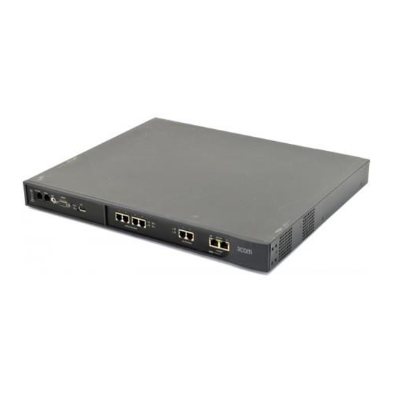
NBX IP Telephony Platforms Table 9 V3000 BRI Connectors and LEDs (continued) ATA (FXS) Two Analog Terminal Adapter ports, RJ-11 FSX (Foreign Exchange Station) connector for connecting an analog device, such as an analog telephone or a fax machine. The LED associated with the port indicates the state of the port: Initialization: Fast steady blink —... - Page 34 1: I HAPTER NTRODUCTION Figure 6 shows the front panel of the V5000 and Table 10 describes each front panel connector and status light. Figure 6 V5000 Connectors and LEDs 9 10 11 12 13 14 15 NBX Call Processor External KYBD Mouse...
- Page 35 NBX IP Telephony Platforms Table 10 V5000 Connectors and LEDs (continued) Network Three LEDs for each of the 2 Ethernet ports indicate port Status LEDs status: LNK — Solid on indicates link; Off indicates no link. ■ 10 — Blinking indicates network activity at 10 MB; ■...
-
Page 36: Nbx Expansion Chassis
1: I HAPTER NTRODUCTION Explanation Using disk 1 only Synchronizing — disk 0 is valid, disk 1 is becoming a Flashing fully mirrored disk. LED 3 flash rate indicates progress. If LED 3 stops normal flashing and intermittently flashes twice, the mirroring process has failed. Synchronizing —... -
Page 37: Nbx Cards And Devices
CAUTION: The power cord is the disconnect device. The power outlet must be near to the unit and easily accessible. NBX Cards and This section lists NBX cards available from 3Com that can you can use Devices with an NBX system. You install the cards in an NBX chassis. -
Page 38: T1 Digital Line Card
1: I HAPTER NTRODUCTION Each Analog Line Card contains the following lights and connectors: Status Lights (1 through 4) — Each light shows the status of the ■ associated line. Initialization: Fast steady blink — Waiting for software download. ■ Solid on —... - Page 39 10BT UPLINK CONSOLE Nominal MDI-X 3C10116C 3Com NBX Digital Line Card Figure 9 T1 Digital Line Card (3C10116D) T1 Digital Line Card has these lights and connectors: 3C10116C T1 — This RJ-48C connector makes a patch cord connection to a T1 ■...
- Page 40 1: I HAPTER NTRODUCTION Status Lights — These lights indicate the status of the T1 card’s ■ signaling, synchronization, and loop back test. CO — Central Office: ■ Amber — Alarm condition at the remote end or the CO is not connected or available.
-
Page 41: E1 Digital Line Card
NBX Cards and Devices Flashing — Audio traffic is present. CARD — Card Software Status ■ Green — The card has finished downloading software from the NCP and all software processes have started successfully. Amber — A problem with one or more of the software processes running on the card. - Page 42 1: I HAPTER NTRODUCTION 3C10165D includes an onboard CSU. The 3C10165D can provide CSU performance statistics, can be enabled for loopback testing, and can be configured as a remote device that communicates with its NCP over a routed network. CAUTION: 3C10165D E1 Digital Line Cards and 3C10116D T1 Digital Line Cards can have their flash memory corrupted if you remove power from the cards or remove the cards from the NBX chassis while they are receiving their download after a system upgrade.
- Page 43 NBX Cards and Devices used in a Gateway Chassis, do not use this connector because the chassis has an Ethernet connector to connect the chassis to the LAN. If you use the Uplink connection, be sure to program the switch or router at the other end for 10BASE-T 10 MB operation.
- Page 44 1: I HAPTER NTRODUCTION Green — The download is complete or the Power-On-Self-Test (POST) is running. Amber — The download was interrupted before it was completed. On a LAN, the download process is completed quickly. If the download from NCP to digital line card must travel a routed network path, the download may take a few minutes.
-
Page 45: Bri-St Digital Line Card
If you require an alternative (bare wire-end) cable to use with the ISDN PRI Digital Line Card, contact your 3Com NBX Voice-Authorized Partner. CAUTION: This equipment does not operate when the main power fails. BRI-ST Digital Line... - Page 46 1: I HAPTER NTRODUCTION Each card has the following lights and connectors: 3C10164C-ST BRI Port Status Lights — Each BRI port has these status lights: ■ D — On when this signaling channel is active. ■ B1 — On when this data channel is active (a call is in progress). ■...
-
Page 47: 10Base-T Uplink Card
196. 10BASE-T Uplink Card The 10BASE-T Uplink Card provides eight 10BASE-T Ethernet ports to connect 3Com Telephones (or other 10BASE-T devices) to the LAN. The Uplink Card replaces the 10BASE-T Hub Card. Figure 14 NBX Uplink Card (3C10370) 1 2 3 4 5 6 7... -
Page 48: Legacy Link Analog Card
A maximum of eight simultaneous FAX calls can be made on the card. The Legacy Link Analog card requires a license and NBX software R.4.1.6 or higher. Figure 17 3Com Legacy Link Gateway for Analog Handsets (16 Port FXS) (3C10392) - Page 49 NBX Cards and Devices Each Legacy Link Analog Card has the following lights and connectors: Status Lights 1 – 16 — All LEDs flash approximately every 10 ■ seconds. On – Handset off-hook (call in progress) ■ Off – Handset on-hook or no handset connected ■...
-
Page 50: Legacy Link Norstar Card
HAPTER NTRODUCTION Legacy Link Norstar The 3Com Legacy Link Gateway for Norstar Handsets provides NBX Card protocol mapping for up to 16 Norstar handsets using existing PBX wiring. A maximum of eight simultaneous FAX calls can be made on the card. -
Page 51: Legacy Link Meridian Card
1 is connected to pins 1 and 26, line 2 is connected to pins 2 and 27, and so on. Legacy Link Meridian The 3Com Legacy Link Gateway for Meridian Handsets provides NBX Card protocol mapping for up to 16 Norstar handsets using existing PBX wiring. -
Page 52: Analog Terminal Adapter
1: I HAPTER NTRODUCTION On – Seek service assistance ■ Off – Operating normally ■ — The power connector is a 6-pin, circular, Mini-DIN type. Power ■ from the external 48V D.C. supply is fed into the card via this connector to power the handsets through the RJ21x 50-way line connector. - Page 53 The ATA has an RS232 DB9 connector that allows a technician to access a command line interface for the device. Only qualified 3Com service personnel should use the serial diagnostic port. The Analog Terminal Adapter has these lights and connectors: Power Light —...
-
Page 54: 3Com Telephones
Table 12 gives a short summary of each 3Com telephone and lists the NBX system software and the type of license required to support each telephone. Table 12 3Com Telephones... - Page 55 NBX Cards and Devices Telephone Part Minimum System License Model Number Software Required Group 3100 Entry Telephone 3C10399A R5.0 Group 0 Provides the convenience of four 3C10399B R5.0.20 fixed-feature buttons for one-touch access in an affordable package for basic IP telephone connectivity.
-
Page 56: Third-Party Devices And Applications
For more information on device licenses, see“Group Device Licenses” ■ page As of July 1, 2006, all 3Com devices put into the market within the ■ European Union meet the requirements of the Reduction of Hazardous Substances Directive, EU Directive 2002/95/EG, (RoHS). -
Page 57: Optional Software
NBX NetSet utility and specify the host PC’s MAC address as the device identifier. To fully support the pcXset Soft Telephone, 3Com recommends a PC with a processor speed of at least 1.8 GHz. When it is installed on a PC with a processor speed of 800 MHz or lower, calls that use the G.729 codec can... -
Page 58: International Feature Support
Connectors NBX V3000 platforms, and each port on the NBX Analog Terminal Card may require a telephone connector for use outside North America. Contact your 3Com NBX Voice-Authorized Partner for information on country-specific requirements. Language Support The NBX Resource Pack includes these localized components: Telephone tones and cadences that match those used by telephone ■... -
Page 59: Nbx Licensing
NBX systems count many physical devices and certain software applications as devices toward the total device limit: Physical Devices — Each 3Com Telephone, each Analog Terminal ■ Adapter, each channel on a Digital Line Card, and each port on an Analog Line Card counts as one device. -
Page 60: Licensed Device Limits
Limits Device licensing is explained in detail in “Device Licenses Details” page 75. Your 3Com NBX Voice-Authorized Partner can provide details on available incremental device licences. You must install an optional memory upgrade to support some features. Table 13 page 63... -
Page 61: How The System Limits Interact
Cards (for analog telephones and FAX machines). The total device count is now (6 x 4) + (12 x 4) = 72. You then configure 450 3Com Telephones. ■ The total device count is now 522. You can configure 978 additional devices (1500–522). - Page 62 1: I HAPTER NTRODUCTION For the current device and license configuration on your system, see Licensing and Upgrades > Licenses as well as the Usage Report accessible from the Licenses screen in the NBX NetSet utility. SIP mode operations are supported on V3001 Analog, V3001 BRI, V3000 Analog, and V3000 BRI systems that have the optional memory upgrade installed.
- Page 63 NBX Licensing Table 13 Detailed Device Limits - V3001 Analog or V3001 BRI Per-Unit Max with Max without Device or Device Count Memory Memory Site License Description Toward Total Upgrade Upgrade Required? A system without the memory upgrade cannot always provide acceptable performance if you configure the maximum number of Phantom Mailboxes, Groups, devices, and Account Codes.
- Page 64 1: I HAPTER NTRODUCTION Table 13 Detailed Device Limits - V3001 Analog or V3001 BRI (continued) Per-Unit Max with Max without Device or Device Count Memory Memory Site License Description Toward Total Upgrade Upgrade Required? Polycom IP 3000 1500 Speaker Phone Legacy Link Handset 1488 (93 240 (15 cards)
- Page 65 NBX Licensing Table 13 Detailed Device Limits - V3001 Analog or V3001 BRI (continued) Per-Unit Max with Max without Device or Device Count Memory Memory Site License Description Toward Total Upgrade Upgrade Required? Voice Mailboxes None 1500 Covered by (NBX Messaging) total system device license...
- Page 66 1: I HAPTER NTRODUCTION Table 13 Detailed Device Limits - V3001 Analog or V3001 BRI (continued) Per-Unit Max with Max without Device or Device Count Memory Memory Site License Description Toward Total Upgrade Upgrade Required? Call Detail None Reporting Call Record and None Monitor TAPI Route Points...
- Page 67 NBX Licensing Table 14 Detailed Device Limits - V3001R (continued) Device/application Per-Unit Device Count System License Description Toward Total Maximum Required? 3105 Attendant Console pcXset Soft 1 per pcXset PC 1500 Telephone telephone client NBX Media Driver 1 driver/system enables 1500 (for WAV devices) the max allowable...
- Page 68 1: I HAPTER NTRODUCTION Table 14 Detailed Device Limits - V3001R (continued) Device/application Per-Unit Device Count System License Description Toward Total Maximum Required? The 3-digit dial plan does not provide enough extensions to support 1000 Phantom Mailboxes. Automatic Call Distribution Groups (above 2 groups) ACD Groups, Hunt Groups, and Calling Groups all count towards the same maximum total.
- Page 69 NBX Licensing Table 15 Detailed Device Limits - V3000 Analog or V3000 BRI Per-Unit Max with Max without Device or Device Count Memory Memory Site License Description Toward Total Upgrade Upgrade Required? A system without the memory upgrade cannot always provide acceptable performance if you configure the maximum number of Phantom Mailboxes, Groups, devices, and Account Codes.
- Page 70 1: I HAPTER NTRODUCTION Table 15 Detailed Device Limits - V3000 Analog or V3000 BRI (continued) Per-Unit Max with Max without Device or Device Count Memory Memory Site License Description Toward Total Upgrade Upgrade Required? Polycom IP 3000 1500 Speaker Phone Legacy Link Handset 1488 (93 240 (15 cards)
- Page 71 NBX Licensing Table 15 Detailed Device Limits - V3000 Analog or V3000 BRI (continued) Per-Unit Max with Max without Device or Device Count Memory Memory Site License Description Toward Total Upgrade Upgrade Required? Voice Mailboxes None 1500 Covered by (NBX Messaging) total system device license...
- Page 72 1: I HAPTER NTRODUCTION Table 15 Detailed Device Limits - V3000 Analog or V3000 BRI (continued) Per-Unit Max with Max without Device or Device Count Memory Memory Site License Description Toward Total Upgrade Upgrade Required? Page Zones None System Speed Dials None Personal Speed Dials None Call Detail None...
- Page 73 NBX Licensing Table 16 Detailed Device Limits - V5000 (continued) Device or Site Device/application Per-Unit Device Count System License Description Toward Total Maximum Required? 3108 Wireless 1500 Telephone pcXset Soft 1 per pcXset PC 1500 Telephone telephone client NBX Media Driver 1 driver/system enables 1500 (for WAV devices)
- Page 74 1: I HAPTER NTRODUCTION Table 16 Detailed Device Limits - V5000 (continued) Device or Site Device/application Per-Unit Device Count System License Description Toward Total Maximum Required? Voice Mailboxes None 1500 Covered by total system device license Because of system performance issues, a V5000 system should have no more than 1000 Phantom Mailboxes.
-
Page 75: Device Licenses Details
NBX Licensing Table 16 Detailed Device Limits - V5000 (continued) Device or Site Device/application Per-Unit Device Count System License Description Toward Total Maximum Required? The 3-digit dial plan might not provide enough extensions to support 100 TAPI Route Points. Device Licenses The basic NBX system includes default licenses. -
Page 76: Group Device Licenses
1: I HAPTER NTRODUCTION NBX Licensing Summary Notes NBX cards, Analog Terminal Adapters, and legacy devices (1102, ■ 2102, 2102-IR Business Telephones, 2101 Basic Telephones, and 1105 Attendant Consoles) do not require a license. The number of these devices is governed solely by the system device license. NBX systems include support for four NBX Messaging ports and a limit ■... -
Page 77: Dynamic License Assignment
3102 and 3102B Business Telephone ■ 3105 Attendant Console ■ The 3Com Convergence Client (supported in SIP mode only) and generic SIP telephones are all Group 1 devices. Dynamic License NBX Group Licensing is a dynamic system that assigns licenses in the Assignment most efficient manner. - Page 78 1: I HAPTER NTRODUCTION Figure 22 Licensing and Upgrades > Licenses > Usage Report The first column in the License Usage Report shows the number of device licenses currently in use. The second column shows the number of licenses in each License Group that have been installed on the system.
- Page 79 NBX Licensing Example 4 — Dynamic License Group Adjustment: You add another 3103 Manager’s Telephone (Group 2 device) to your an NBX system that has no licenses available in any group. The system will not enable the new telephone. You could add another Group 2 license, but it would be more cost-effective to add a less expensive Group 0 license instead.
- Page 80 1: I HAPTER NTRODUCTION...
-
Page 81: Installing System Hardware Components
NSTALLING YSTEM ARDWARE OMPONENTS This chapter explains how to install standard and optional hardware components for the NBX Networked Telephony System. This chapter includes information about using the Auto Discover feature to add telephones. See Chapter 3 for more detailed information about adding telephones. -
Page 82: Installation Requirements
Requirements sections before you install the NBX system. 3Com does not support more than one NBX system on a local area network. You can connect NBX systems over a WAN (using VTLs or SIP trusted endpoints), however, installing more than one NBX system on a LAN can cause unpredictable results. -
Page 83: Physical Requirements
Each analog telephone line has dial tone. ■ CAUTION: 3Com strongly recommends that you use UL-listed surge suppression devices on all local telephone lines. If you are installing an optional BRI-ST, T1, or E1 Digital Line Card, ■... -
Page 84: Analog Terminal Connectors
Involved? can connect to the NBX system through an Analog Terminal Adapter. CAUTION: To avoid damage to any 3Com telephone, do not connect it directly to a standard telephone line. Although the RJ-11 connector for a traditional telephone fits into the 3Com telephone’s RJ-45 jack, the... -
Page 85: What External Devices Can Connect To An Nbx System
The receiving NBX device can be another 3Com telephone or for external calls it can be an analog line port or a channel on an NBX Digital Line Card. -
Page 86: Before You Begin Installation
2: I HAPTER NSTALLING YSTEM ARDWARE OMPONENTS NBX System Quality of Service Quality of Service (QoS) is a way to allocate resources in switches and routers so that data can be prioritized. Time-sensitive data receives higher priority. At Layer 2, the NBX system supports Ethernet 802.1Q, “Standard for Virtual Bridged Local Area Networks,”... -
Page 87: Required And Recommended Tools And Equipment
Important Safety Information Verify that an existing LAN is in place and is operational and that LAN ■ port connections are available. Read and follow the safety notes and precautions later in this chapter. ■ Required and These items are typically required to install an NBX system: Recommended Tools Screwdrivers (flat and Phillips) ■... - Page 88 Do not staple the power cord or otherwise attach it to building ■ surfaces. Do not use any AC power converter on a 3Com device other than the ■ one that is shipped with the device. On 3Com PoE-compliant devices, the power converter is an optional component.
-
Page 89: Lithium Battery Safety
Safety WARNING: The battery is not field replaceable. If you suspect a battery failure, contact your 3Com NBX Voice-Authorized Partner. There is a danger of explosion if the battery is incorrectly replaced. Replace the battery only with the same or equivalent type as recommended by the manufacturer. - Page 90 2: I HAPTER NSTALLING YSTEM ARDWARE OMPONENTS AVERTISSEMENT: Vérifiez que le systeme est paramétré sur le réglage de tension conforme aux exigences du pays d’utilisation. AVERTISSEMENT: Le systeme doit être rangé (verrouillé) dans un endroit sûr et seul le personnel ayant reçu une formation peut y avoir accès. L’installation et la dépose de cette unité...
-
Page 91: Batterie Au Lithium
Wichtige Sicherheitsinformationen Le coupleur d’appareil (le connecteur de l’unité et non pas la prise ■ murale) doit respecter une configuration qui permet un branchement sur une entrée d’appareil EN60320/IEC 320. La prise secteur doit se trouver à proximité de l’appareil et son accès ■... - Page 92 2: I HAPTER NSTALLING YSTEM ARDWARE OMPONENTS Das Gerät nicht an eine Wechselstromsteckdose anschließen, die über ■ keine Schutzerdung verfügt. Das Gerät muß an eine Steckdose mit Schutzerdung angeschlossen ■ werden, die internationalen Sicherheitsvorschriften und den Vorschriften zur EMV entspricht. Netzkabelsatz: ■...
-
Page 93: Lithiumbatterie
You should record the MAC addresses of the ports that interface with CO Addresses equipment. If you will be installing optional cards into a chassis, 3Com recommends that you install one card at a time, and that you install the cards in the order of the MAC addresses of the ports on the card. -
Page 94: Mounting An Nbx System In An Equipment Rack
2: I HAPTER NSTALLING YSTEM ARDWARE OMPONENTS A well-organized physical configuration can simplify: Management of incoming telephone lines, by associating line card ■ ports with specific telephone numbers Troubleshooting, by associating groups of channel numbers with ■ specific cards System expansion ■... - Page 95 Installing the NBX System Hardware you purchased one) is packaged separately for you to install. If you are not installing a second disk with your NBX system, you can skip this section and proceed to “Powering Your NBX System” page Disk Mirroring is enabled when you install the disk mirroring license key in the NBX NetSet utility.
- Page 96 2: I HAPTER NSTALLING YSTEM ARDWARE OMPONENTS V5000 Disk Mirroring To install an additional disk drive for disk mirroring on a V5000: 1 Install the key code for your disk mirroring license, Licensing and Upgrades > Licenses. 2 Shut down system software, System Maintenance > Reboot / Shutdown. 3 Turn off power to your system.
- Page 97 Installing the NBX System Hardware V3001R Disk Mirroring To install an additional disk drive for disk mirroring on a V3001R: 1 If you have not already done so, login to the NBX NetSet utility as administrator and perform a data backup. CAUTION: V3001R disk drives are not “hot-swappable.”...
-
Page 98: Powering Your Nbx System
If you disconnect power during the flash upgrade, the boot software may become corrupted and the system will need to be returned to 3Com for repair. As the flash upgrade progresses, the system Console displays these messages: Upgrade Older PROM... - Page 99 Installing the NBX System Hardware Upgrading NCP Flash ..Number of attempts to upgrade the flash = 1 NCP Flash Upgrade Complete To turn on power to the NBX system and optional NBX chassis, follow these steps: 1 Attach a power cord to the unit. For a a V5000 or a chassis, attaching the power cord applies power to the unit.
-
Page 100: Configuring Nbx System Networking
2: I HAPTER NSTALLING YSTEM ARDWARE OMPONENTS Configuring NBX Configuring the networking for the NBX system involves these steps: System Networking Establishing IP Connectivity ■ Establishing LAN Connections ■ Establishing IP You need IP connectivity to use the NBX NetSet utility to configure and Connectivity manage the NBX system.You do not need to install any special software to run the NBX NetSet utility, but you must have Microsoft Internet... - Page 101 Configuring NBX System Networking There are two different methods you can use to configure the NBX system’s IP settings: Connect a serial cable from a computer to the NBX system Console ■ port and use the command line interface to set the NBX system IP settings.
- Page 102 2: I HAPTER NSTALLING YSTEM ARDWARE OMPONENTS 2 Record the existing IP settings on the computer so you can restore them later and then change the IP settings of your computer to: IP address: 192.168.1.191 Default gateway: 0.0.0.0 Subnet mask: 255.255.255.0 CAUTION: Do not set your computer address to 192.168.1.192 because that IP address is used temporarily during system startup.
- Page 103 Configuring NBX System Networking Table 21 IP Addressing and the NBX System Local IP Environment NBX System Configuration No IP networking You do not need to change the IP settings in the NBX currently in use system, but you probably need to configure the IP settings in the computer that you use to communicate with the NBX NetSet utility.
-
Page 104: Establishing Lan Connections
2: I HAPTER NSTALLING YSTEM ARDWARE OMPONENTS Establishing LAN After you configure the NBX system IP settings, you are ready to connect Connections the system to your LAN. 1 Connect NBX system and any optional NBX chassis to your LAN using the devices’s Ethernet port. -
Page 105: Connecting Cards And Devices
Configuration” page 111. 3Com recommends that you install the cards in MAC address order. This practice makes it easier to diagnose and troubleshoot problems. Mapping Line Card Ports to Telephone Lines You can run the system using the default configuration, but to have... -
Page 106: Connecting Digital Line Cards
2: I HAPTER NSTALLING YSTEM ARDWARE OMPONENTS continues to provide dial tone and telephone service. Do not count this port as a line port. Connecting Digital You can install cards with the power on to the chassis. To connect and Line Cards configure the digital line cards: 1 Remove one of the blank faceplates from the chassis. -
Page 107: Connecting An Analog Terminal Adapter
Connecting Cards and Devices The Auto Discover process finds each port on each Analog Terminal Card and assigns port extensions. Connecting an If you are installing one or more Analog Terminal Adapters (ATA), install Analog Terminal them after installing chassis cards. Adapter To install an ATA: 1 Connect the analog telephone or fax machine to the analog port on the... - Page 108 2: I HAPTER NSTALLING YSTEM ARDWARE OMPONENTS 4 Connect the AC power adapter to the AC power connector on the ATA. If you are using a powered Ethernet cable instead of the AC adapter, see “Using Power over Ethernet with an ATA” next.
-
Page 109: Selecting Regional Software And Components
■ (24-port) CAUTION: You can damage an NBX device by using an NBX power splitter (3C10223) with the 3Com Network Jack Power over Ethernet Multiport Midspan Solution (3CNJPSE24). Use the NBX power splitter (3C10223) only with the 3Com Ethernet Power Source (3C10220, 12-port, or 3C10222, 24-port). -
Page 110: Installing Regional Software And Components
2: I HAPTER NSTALLING YSTEM ARDWARE OMPONENTS Tones and cadences ■ Localized User Help for the NBX NetSet utility ■ Localized NBX Telephone Guides and Quick Reference Guides, which ■ are accessed from the NBX NetSet utility and the Resource Pack. NBX 6.0 and higher includes a localized NBX NetSet utility interface for telephone users. -
Page 111: Using Auto Discover For Initial System Configuration
Initial System “Devices” include telephones, Analog Line Card ports, Digital Line Card Configuration channels, Analog Terminal Adapter ports, 3Com Attendant Consoles, and “virtual devices” such as the pcXset Soft Telephone. CAUTION: 3C10165D E1 Digital Line Cards and 3C10116D T1 Digital... -
Page 112: Initial System Configuration
(receptionist). 3Com Attendant Console Finds and configures any installed 3Com Attendant Consoles. The first 100 existing telephones, except for the extension that is associated with the Attendant Console, are mapped to Attendant Console buttons. The lowest extension is automatically associated with the Attendant Console. - Page 113 System-wide Settings > Auto Discovery 5 Select the check box for the device type you are configuring, and then click Apply. 3Com recommends that you Auto Discover one device type at a time. For detailed information about each field, click the Help button on the page.
-
Page 114: Disabling The Auto Discover Feature
CO line. Auto Extension specifies the destination of a call that is not answered at any of the telephones. The system must be using 3Com call control mode because you cannot map telephone lines to phone buttons if the NBX system is operating in SIP mode. -
Page 115: Reassigning Extensions And Setting Line Card Port Options
■ Some CO lines are mapped directly to telephones, while the rest are pooled. The system must be using 3Com call control mode because you cannot map telephone lines to phone buttons if the NBX system is operating in SIP mode. See the NBX Administrator’s Guide for more information on SIP on the NBX. - Page 116 2: I HAPTER NSTALLING YSTEM ARDWARE OMPONENTS Table 25 Examples of Line Card Addresses Analog Line Card (3C10114) Analog Line Card (3C10114C) MAC Address Extension MAC Address Extension 00:e0:bb:03:8d:c8 7260 00:e0:bb:03:8d:cc(1) 7260 00:e0:bb:03:8d:c9 7261 00:e0:bb:03:8d:cc(2) 7261 00:e0:bb:03:8d:ca 7259 00:e0:bb:03:8d:cc(3) 7259 00:e0:bb:03:8d:cb 7258 00:e0:bb:03:8d:cc(4)
-
Page 117: Connecting Telephone Lines
1 Use a nonferrous (plastic or aluminum) adjustment tool to adjust the volume control on the front of the Call Processor to about mid-range. 2 Use a 3Com Telephone to call another extension, and have the person put you on hold. -
Page 118: Configuring Routing Devices
2: I HAPTER NSTALLING YSTEM ARDWARE OMPONENTS The paging connector on the NCP is an RJ-11 connector. It is a line-out, 600 ohm audio interface with a dry contact closure for use with an external paging amplifier (Table 26). Table 26 Paging Amplifier Connector Pin 1 Not connected Pin 2... - Page 119 Configuring Routing Devices Table 27 Layer 2 Multicast Addresses Multicast Address Description 01:e0:bb:00:00:3d Conference 4 01:e0:bb:00:00:30 Conference 5 01:e0:bb:00:00:34 Conference 6 01:e0:bb:00:00:3c Conference 7 01:e0:bb:00:00:38 Conference 8 01:e0:bb:00:00:28 Conference 9 01:e0:bb:00:00:2c Conference 10 01:e0:bb:00:00:24 Conference 11...
- Page 120 2: I HAPTER NSTALLING YSTEM ARDWARE OMPONENTS...
-
Page 121: Telephones And Attendant Consoles
Telephones telephone. When you enable the Auto Discover feature and then connect a new 3Com Telephone to the LAN, the telephone receives the next lowest available extension and a default set of properties. You can then move the telephone to another location on the LAN and it retains its extension number. - Page 122 NCP, but to do so you must first configure the network information in the telephone using a option 184 on your DHCP server, the Telephone Local User Interface utility (LUI), or the 3Com Telephone Local Configuration Application. These options are described in the NBX Administrator’s Guide.
- Page 123 Adding Telephones 5 For each telephone that you want to Auto Discover: a Remove the telephone from the packing box. b Connect power to the telephone as described on page 124 or on the packing sheet that comes with the telephone. c Connect the telephone to the LAN on which the NCP resides as described on page 126...
-
Page 124: Manually Configure Telephones
NCP by using the Telephone Local User Interface utility (LUI) or the 3Com Telephone Local Configuration application (TLC). The LUI utility resides on each 3Com telephone. You can install the TLC application to your PC by clicking Downloads > Applications For details about these tools, see the NBX Administrator’s Guide. - Page 125 ■ ■ NOTE: If you use a power brick on a 3103 Manager’s Telephone, you must use the 3C10444-XX power brick. All other 3Com devices can use either 3C10444-XX or the older power brick, 3C10224-XX. Power over 3103 Managers Telephone:...
-
Page 126: Connecting The Telephone To The Lan
3100 Entry Telephone: 3C10399A; 3C10399B CAUTION: You can damage an NBX device by using an NBX power splitter (3C10223) with the 3Com Network Jack Power over Ethernet Multiport Midspan Solution (3CNJPSE24). Use the NBX power splitter (3C10223) only with the 3Com Ethernet Power Source (3C10220, 12-port, or 3C10222, 24-port). - Page 127 Adding Telephones Figure 26 Connections for 3Com 3102 Business Telephone (shown) and 3103 Manager’s Telephone Power cable. Ask your Administrator how you should power your phone. Then see Table 28 for instructions on how to connect your telephone to power.
- Page 128 Ethernet cable (optional; to connect a computer or an Attendant Console to the network) Handset cord (to handset) Ethernet cable (to data jack) Figure 29 Connections for 3Com 3101 and 3101SP Basic Telephones (shown) and 3100 Entry Telephone Power cable. Ask your Administrator how you should power your phone. Then see...
- Page 129 Connect the other end of the cable to the Ethernet switch port on the ■ underside of the telephone. The Ethernet port is labeled with this icon: Do not use the telephone’s Ethernet port to connect another 3Com ■ telephone to the system.
-
Page 130: 3Com Cordless Telephones
For installations of three or fewer cordless telephones, 3Com recommends that you use 3107C Telephones. For installations of 3 to 10 cordless telephones, 3Com recommends that you use 3106C Telephones. Table 29 shows the telephones’... -
Page 131: 3Com Entry Telephones
Adding Telephones 3Com Entry The 3Com 3100 Entry Telephone does not have a display panel to show Telephones the status of the process of initializing the telephone when you connect it to an NBX system or when you reboot the phone of the NBX system. -
Page 132: Verifying Telephone Installation
3: T HAPTER ELEPHONES AND TTENDANT ONSOLES Table 30 3100 Entry Telephone Initialization Status Blink Pattern Telephone State Notes 10 blinks in 2 seconds The 3100 has detected Configure the network more than one NBX correctly so that only a single Pause 2 seconds system on the local NBX system is on the subnet. -
Page 133: Adding A 3Com Attendant Console
You can associate any 3Com telephone with an attendant console. However, if you use a 3Com 3103 Managers Telephone, you cannot map a CO line directly to a button on the Attendant Console and the Attendant Console will not support Bridged Station Appearances. - Page 134 3Com Ethernet power sources that predate 802.3af ■ Table 31 for power connection instructions for 3Com Attendant Consoles. Table 31 Connecting Power to a 3Com Attendant Console Power Source Connection Details AC power adapter Connect the AC adapter’s power jack to the...
-
Page 135: Connecting The Attendant Console To The Network
Adding a 3Com Attendant Console Table 31 Connecting Power to a 3Com Attendant Console (continued) Power Source Connection Details 3Com Ethernet Power Source: The 3Com Ethernet Power Source predates 802.3af so you must use 3C10220 (12-port) ■ a 3Com NBX Telephone Power... -
Page 136: Associating An Attendant Console With A Specific Telephone
You can associate any 3Com telephone with an attendant console. Attendant Console However, if you use a 3Com 3103 Manager’s Telephone, you cannot map with a Specific a CO line directly to a button on the Attendant Console and the Telephone Attendant Console will not support Bridged Station Appearances. -
Page 137: Verifying Extension Assignments On An Attendant Console
2 Click Downloads > LabelMaker. After you print the labels and then cut them out, remove the plastic cover from the Attendant Console and install the labels. On the 3Com 3105 Attendant Console, remove the cover by pulling up on the two tabs at... -
Page 138: Adding A Remote Telephone
Telephone Port Translation (NAPT, also called NAT overloading). NAPT allows you to put a 3Com Telephone behind a device that applies network address translation at a remote location, such as a home office, and connect to the NBX NCP through an Internet connection. One typical configuration is to connect a cable/DSL modem to a small office/home office router that includes a firewall and Ethernet ports. -
Page 139: Analog Lines
NALOG INES This chapter tells you how to install and how to verify the successful installation of optional Analog Line Cards and to configure analog ports. The NBX system treats a line card port as an extension and assigns a unique extension number to each port. -
Page 140: Inserting An Analog Line Card
4: A HAPTER NALOG INES Inserting an When you insert an Analog Line Card into an NBX chassis, you may leave Analog Line Card the system powered up. The Auto Discover process begins as soon as the system detects the new card. To insert the Analog Line Card: 1 Find the MAC address of the card on the label on the card. -
Page 141: Using Status Lights
Verifying an Analog Line Card Table 32 MAC Addresses for the Ports on an Analog Line Card ATA Card or Port MAC Address Extension Port 1 00:e0:bb:03:91:45 7251 Port 2 00:e0:bb:03:91:46 7250 Port 3 00:e0:bb:03:91:47 7252 Port 4 00:e0:bb:03:91:48 7253 The ports on an Analog Line Card are usually not auto discovered in order. - Page 142 4: A HAPTER NALOG INES...
-
Page 143: Analog Devices
A user cannot forward calls to voice mail by enabling a button such as ■ the FWD MAIL button on the 3Com Business Telephone. You can use a feature code to have the system automatically transfer calls to voice mail if your analog telephone is not answered. -
Page 144: Adding An Analog Terminal Card
5: A HAPTER NALOG EVICES To transfer a call from an analog telephone, you must depress the ■ hook switch briefly to obtain dial tone, and then dial the extension to which you want to transfer the call and hang up. By using feature codes, you can create conference calls and forward ■... -
Page 145: Verifying Analog Terminal Card Ports
To add an Analog Terminal Adapter (ATA) to your NBX system you must Terminal Adapter first enable the Auto Discover feature. You Auto Discover an Analog (ATA) Terminal Adapter (ATA) in the same way that you discover 3Com telephones and Analog Terminal Cards. “3Com Telephones” page 54 for information on system software and licensing requirements for an ATA. -
Page 146: Connecting The Analog Terminal Adapter
5: A HAPTER NALOG EVICES “3Com Telephones” page 54 for information on system software and licensing requirements. 1 Log in to the NBX NetSet utility using the administrator username and password. 2 Click System-wide Settings > Auto Discovery 3 Enable the Auto Discover Other Devices check box. -
Page 147: Verifying An Analog Terminal Adapter Or The Ata Port
ATA’s LAN port (labeled LAN) and power connection (labeled CAUTION: You can damage an NBX device by using an NBX power splitter (3C10223) with the 3Com Network Jack Power over Ethernet Multiport Midspan Solution (3CNJPSE24). Use the NBX power splitter (3C10223) only with the 3Com Ethernet Power Source (3C10220, 12-port, or 3C10222, 24-port). - Page 148 5: A HAPTER NALOG EVICES 3 Use the MAC address that you recorded prior to installing the ATA to identify it in the list. The MAC address on the ATA and the MAC address displayed in the list on the ATA tab should be identical. Use the status lights on an ATA to help verify that the ATA has been properly discovered.
-
Page 149: Bri-St Digital Line Card
BRI-ST D IGITAL This chapter tells you how to install and verify the installation of the optional ISDN BRI-ST (Basic Rate Interface) Digital Line Card. For information about installing the system hardware components, see Chapter The following sections describe how to add and configure a BRI-ST Digital Line Card to handle four BRI spans using the ST interface. -
Page 150: Adding A Bri-St Digital Line Card
6: BRI-ST D HAPTER IGITAL Adding a BRI-ST To add an ISDN BRI-ST Digital Line Card to an NBX system, use the Digital Line Card information in these sections: Preparing the NBX System for BRI Cards ■ Ordering DID, CLIP, and MSN Services for BRI ■... -
Page 151: Enabling The Auto Discover Feature
Adding a BRI-ST Digital Line Card passes you three digits, you need no translator entries in the Dial Plan configuration file. If the carrier passes you four digits, you could add a single set of translator entries to the configuration file to remove the first digit (4) and use the remaining three digits as the internal extension. -
Page 152: Verifying A Bri-St Digital Line Card
6: BRI-ST D HAPTER IGITAL Verifying a BRI-ST After you Auto Discover a BRI-ST Digital Line Card, you can verify that it Digital Line Card was properly discovered by using the NBX NetSet utility, described next, or by viewing the card’s status lights, which is described later. Using the NBX NetSet To verify that the BRI-ST card has been properly discovered: Utility... -
Page 153: E1 Isdn Pri Digital Line Card
E1 ISDN PRI D IGITAL This section describes how to add an E1 Digital Line Card and how to connect to an E1 service provided by the local telephone company. In the NBX NetSet utility, digital line cards are referred to as either cards or boards. -
Page 154: Adding An E1 Digital Line Card
7: E1 ISDN PRI D HAPTER IGITAL Adding an E1 The following sections tell you how to add an E1 Digital Line Card to an Digital Line Card NBX system: Preparing the NBX System for E1 Cards ■ Ordering DID, CLIP, and MSN Services for E1 ■... -
Page 155: Enabling The Auto Discover Feature For Digital Line Cards
Adding an E1 Digital Line Card 617-555-4100 through 617-555-4299. If the local telephone carrier passes you three digits, you need no translator entries in the Dial Plan configuration file. If the carrier passes you four digits, you could add a single set of translator entries to the configuration file to remove the first digit (4) and use the remaining three digits as the internal extension. -
Page 156: Verifying An E1 Digital Line Card
7: E1 ISDN PRI D HAPTER IGITAL Verifying an E1 After the Auto Discover process is completed, you can verify that the E1 Digital Line Card Digital Line Card has been properly discovered by using the NBX NetSet utility, described next, and by examining the status light on the Digital Line Card, described on page 156. -
Page 157: T1 Digital Line Card
T1 D IGITAL This chapter tells you how to install a T1 Digital Line Card. In the NBX NetSet utility, digital line cards are referred to as either cards or boards. The following sections describe how to add a T1 Digital Line Card (3C10116C and 3C10116D) and how to connect to a T1 service provided by the local telephone company: Adding a T1 Digital Line Card... -
Page 158: Adding A T1 Digital Line Card
8: T1 D HAPTER IGITAL Adding a T1 Digital Adding a T1 Digital Line Card to a system requires: Line Card Preparing the NBX System for a T1 Card ■ Ordering DID (Direct Inward Dialing) Services for T1 ■ Enabling Auto Discover for Digital Line Cards ■... -
Page 159: Enabling Auto Discover For Digital Line Cards
Adding a T1 Digital Line Card If the DDI/DID numbers match your internal extension numbers, the translator entries in your Dial Plan configuration file can be much simpler. Example: You plan to use internal extensions from 100 through 299, and the local telephone company assigns you numbers from 617-555-4100 through 617-555-4299. -
Page 160: Verifying The T1 Digital Line Card
8: T1 D HAPTER IGITAL 6 Wait at least 3 minutes. When you first insert the T1 card it must initialize and the NBX system must update its database. You must wait 3 minutes because the T1 card reboots twice during the initialization process. On a system with many devices, you may need to allow additional time. - Page 161 Verifying the T1 Digital Line Card For a complete description of the status lights on the front of the card, “T1 Digital Line Card” page You are now ready to configure the T1 Digital Line Card for either DS1 signaling or ISDN PRI signaling. See Chapter 2, “Device Configuration,” in the NBX Administrator’s Guide for instructions.
- Page 162 8: T1 D HAPTER IGITAL...
-
Page 163: Om Legacy Link Cards
3Com Legacy Link Cards are not compatible with an NBX system that has been SIP-enabled. 3Com Legacy Link The 3Com Legacy Link Analog Card fits into an available slot in an NBX Analog Card chassis. It translates the analog handset protocol to a format suitable for use with an NBX system. -
Page 164: 3Com Legacy Link Meridian Card
NBX chassis, be sure you have an AC power point (preferably UPS-protected) within 5 feet of the installation location. NBX chassis: Install no more than two 3Com Legacy Link Cards in an ■ NBX chassis. If additional 3Com Legacy Link Cards are required, use additional NBX chassis. -
Page 165: 3Com Legacy Link Norstar Card
■ external power source. No additional phone power is required. 3Com Legacy Link The 3Com Legacy Link for Norstar card enables the an NBX system to Norstar Card support legacy Nortel Norstar handsets. Each Legacy Link for Norstar card supports up to 16 handsets. The card connects to the Norstar handsets using the existing telephone wiring, punchdown blocks, and connectors. -
Page 166: Adding A Legacy Link Card To An Nbx System
The Norstar phones are line-powered from the card through an ■ external power source. No additional phone power is required. The 3Com Legacy Link cards do not support compression. Voice traffic ■ between a legacy handset and an NBX device that supports compression will be uncompressed. -
Page 167: Prerequisites For Installing A Legacy Link Card
Be sure to read and comply with the Safety Information in the ■ Statutory Warnings Section of the Analog Approvals document on the 3Com Partner Access web site. Be sure to communicate the safety information to users and administrators of the NBX system in which the card is operating. -
Page 168: Adding The Legacy Link License Key
9: 3C HAPTER EGACY ARDS Adding the Legacy You must use the NBX NetSet utility to add the Legacy Link license key Link License Key before the system will recognize a Legacy Link Card. 1 Log in to the NBX NetSet utility using the administrator login ID and password. -
Page 169: Removing A Card
Auto Discover feature. Removing a Card To remove a 3Com Legacy Link Card from an NBX system, wear an anti-static wrist strap and follow the reverse procedure to that used to install the card. -
Page 170: Configuring A Legacy Link Card
EGACY ARDS Configuring a There is no configuration necessary for a 3Com Legacy Link Card except Legacy Link Card when Standard IP or IP on the Fly is enabled on the NBX system. If you are using Standard IP or IP on the Fly on your NBX system, you must use the GWconfig utility, a Windows program, to assign IP address settings to your Legacy Link card. -
Page 171: General Prerequisites
Upgrading Legacy Link Card Software To check the Legacy Link Card Software Version: 1 Log in to the NBX NetSet utility using the administrator login ID and password. 2 Click PSTN Gateway Configuration > ATA. 3 Select a port on the Gateway card, click the extension, and then click the Status tab to view the Software Version. - Page 172 9: 3C HAPTER EGACY ARDS Installing the Gateway Uploader The upload package is supplied as a set of files in a zipped folder. These may be installed anywhere convenient on your PC. Unzip the zip file provided in the Citel Technologies Gateway Uploader Software Upgrade Release, into a new folder named according to the software release version (<myfolder>).
-
Page 173: Upgrading Software Versions 3.0.0.0 And Later
Upgrading Legacy Link Card Software 10 Disconnect the serial cable from the Gateway card. 11 Ensure that the Gateway card has completed its reboot (check indicator LEDs on the front panel). 12 Re-connect the RJ21 and external power connectors to the front of the Gateway card. -
Page 174: Troubleshooting Legacy Link Card Installation
Norstar handsets. CAUTION: Phone cables should be clearly labeled, especially if other 3Com Legacy Link Cards are in use on the same site. The operating voltage on the phone cable varies between different 3Com Legacy Link... - Page 175 RJ21x Wiring for North America models, and incorrect connection may result in damage to cards and/or phones. Legacy Link Cards use only the first 16 pairs of wires of the 25-pair cable for the handsets. The remaining pairs have no connection and are not used.
- Page 176 9: 3C HAPTER EGACY ARDS Table 33 Card Wiring for North American Analog Handsets Wire Color Port Handset RJ11 Pin White-Blue Blue-White White-Orange Orange-White White-Green Green-White White-Brown Brown-White White-Slate Slate-White Red-Blue Blue-Red Red-Orange Orange-Red Red-Green Green-Red Red-Brown Brown-Red Red-Slate Slate-Red Black-Blue Blue-Black Black-Orange...
- Page 177 RJ21x Wiring for North America Card Wiring Chart for Meridian Handsets Table 34 Wire Color Port Handset White-Blue Blue-White White-Orange Orange-White White-Green Green-White White-Brown Brown-White White-Slate Slate-White Red-Blue Blue-Red Red-Orange Orange-Red Red-Green Green-Red Red-Brown Brown-Red Red-Slate Slate-Red Black-Blue Blue-Black Black-Orange Orange-Black Black-Green Green-Black...
- Page 178 9: 3C HAPTER EGACY ARDS Card Wiring Chart for Norstar Handsets Table 35 Wire Color Port Handset White-Blue Blue-White White-Orange Orange-White White-Green Green-White White-Brown Brown-White White-Slate Slate-White Red-Blue Blue-Red Red-Orange Orange-Red Red-Green Green-Red Red-Brown Brown-Red Red-Slate Slate-Red Black-Blue Blue-Black Black-Orange Orange-Black Black-Green Green-Black...
-
Page 179: Configuring Ip Telephony
IP T ONFIGURING ELEPHONY This chapter describes IP telephony and provides instructions for configuring IP. It covers these topics: IP Telephony Overview ■ Implementing IP ■ Standard IP Configuration ■ IP On-the-Fly Configuration ■ Providing the NCP IP Address to Devices ■... -
Page 180: Ip Telephony Overview
10: C IP T HAPTER ONFIGURING ELEPHONY IP Telephony You can integrate the NBX system into any network infrastructure Overview because it can operate at either Layer 2 (Ethernet) or Layer 3 (IP). For information on configuring an NBS system to run SIP mode, see the NBX Administrator’s Guide. -
Page 181: Standard Ip Configuration
IP addresses to handle the number of telephones and devices in the NBX system. If you are not using a DHCP server, use the NBX NetSet utility to configure an IP address for each 3Com telephone and device. Some telephones are on separate subnetworks. ■... -
Page 182: Ip On-The-Fly Configuration
Program the IP address of the NCP directly into each telephone using ■ the telephone key pad. For devices the 3Com 3100 Entry Telephone, which does not have an LCD display panel, you can use the Telephone Local Configuration application, which you can install on a computer from the NBX Resource Pack. -
Page 183: Configuring Ip Telephony
Configuring IP Telephony RFC 2132 (DHCP Options and BOOTP Vendor Extensions) defines vendor specific options that allow you to configure the server to send locally defined information to DHCP clients. NBX system devices support option 184. If you create and activate option 184 on your DHCP server, and use it to specify the IP address of the NCP, you do not need to manually configure the address on the NBX devices. -
Page 184: Configuring Ip On-The-Fly
10: C IP T HAPTER ONFIGURING ELEPHONY Configuring IP Before you configure IP On-the-Fly, consider how many addresses you On-the-Fly need. The number of addresses needed depends on the number of devices that are likely to use IP communications at one time and in one device location. -
Page 185: Manually Configuring Telephone Ip Settings
Configuring IP Telephony you needed to initialize the card by connecting it to the same subnet as the NCP if you were installing the card on a subnet that was remote from the system’s NCP. With NBX R6.0 or higher, these cards support DHCP option 184. -
Page 186: Automatically Configuring Telephone Ip Settings
Configuration application. For detailed instructions on how to use these tools, see the NBX Administrator’s Guide. Automatically When you connect a 3Com Telephone to a network, it searches for a Configuring DHCP server. If the telephone is on the same subnet as the NCP, the... -
Page 187: Configuring Analog Line Card Port Ip Settings
The methods for configuring special options vary depending on the DHCP server, and the example in the NBX Administrator’s Guide may not apply directly to your DHCP server. For assistance, contact your network administrator, the vendor of the DHCP server, or a qualified 3Com service representative. Configuring Analog... - Page 188 10: C IP T HAPTER ONFIGURING ELEPHONY To manually configure channel IP addresses: 1 Log in to the NBX NetSet utility using the administrator username and password. 2 If you have not already done so, use the Auto Discover feature or manual configuration to add the T1, E1, or ISDN BRI channels to the configuration database.
-
Page 189: Low-Bandwidth Telephony
Configuring IP Telephony Low-bandwidth To support remote users, you can configure a 3Com Telephone to operate Telephony over a low-bandwidth link. For reliable audio, the link must support throughput of at least 64 Kbps. An example is a single B channel of a Basic Rate Interface (BRI) ISDN line or a single channel on a T1 line. -
Page 190: Broadband Telephony
NCP and the remote telephone depend on the type of equipment and the Telco/ISP that you use. For help in selecting equipment and configuring it, contact your 3Com NBX Voice-Authorized Partner or a 3Com-qualified support technician. After you enable low-bandwidth communication for a telephone, complete the configuration of the low-bandwidth IP connection: 1 Use the telephone key pad to configure IP settings on the telephone. - Page 191 To add a broadband connected telephone behind a NAPT device: 1 Make sure the NBX system is set up for IP operations, either Standard IP or IP On-the-Fly. 3Com recommends that you use a VPN connection to establish access from your home system to the NBX system network to avoid security issues on the NBX system.
- Page 192 10: C IP T HAPTER ONFIGURING ELEPHONY...
-
Page 193: Troubleshooting
1 Disconnect power to the chassis that characters. holds the NCP. 2 Wait 60 seconds. 3 Reconnect power to the system. 4 Use NBX NetSet to enter the correct date and time. Problem with Contact your 3Com NBX Network NCP battery. Voice-Authorized Partner. - Page 194 11: T HAPTER ROUBLESHOOTING Table 36 Troubleshooting Actions (continued) Symptom Possible Cause Suggested Action Your browser No IP connectivity Verify that the computer you are using to cannot connect run the browser has network connectivity. to the NBX See“Establishing IP Connectivity” NetSet utility.
- Page 195 System-level Troubleshooting Table 36 Troubleshooting Actions (continued) Symptom Possible Cause Suggested Action Lose date and Problem with the “Servicing the Network Call Processor time when battery on the NCP. Battery” page 197. rebooting the system. NBX NetSet is Your network uses a A common networking practice is to very slow in proxy server for...
-
Page 196: Connecting A Computer To A Console Port
10101 3Com 3105 Attendant Console Serial To connect to the serial port on a 3Com 3105 Attendant Console, you must use a DB9 (female)-to-RJ-45 adapter. It does not matter which computer operating system you use. As long as the computer has a terminal emulation program that can emulate a... -
Page 197: Servicing The Network Call Processor Battery
IP nbxIpConfig address settings required by the NCP and other NBX devices. For any other purpose, 3Com recommends that you use the command line interface only under the direction of an authorized service technician. Servicing the... - Page 198 11: T HAPTER ROUBLESHOOTING...
-
Page 199: Specifications
PECIFICATIONS Specifications for NBX hardware: V3000 Analog Call Processor Legacy Link Analog Card V3000 BRI Call Processor Legacy Link Meridian Card V3001 Analog Call Processor Legacy Link Norstar Card V3001 BRI Call Processor 3100 Entry Telephone V3001R Call Processor 3101 and 3101SP Basic Telephones V5000 Call Processor 3102 Business Telephone V3000 Gateway Chassis... -
Page 200: Government Approvals
A: S PPENDIX PECIFICATIONS Government ® The 3Com Networked Telephony Solutions are in compliance with the Approvals industry standards listed in this section. Safety IEC60950 Edition 3 (plus all national deviations) EN60950 1992 / A11: 1997 (plus ZB & ZC deviations) UL 60950-1 CSA 22.2#950 3rd Edition... -
Page 201: Other Approvals
Government Approvals Other Approvals EN61000-3-2 Harmonic emission EN61000-3-3 Flicker CTR3/A1 BRI Interface CTR4/A1 PRI Interface ACA TS031 Australian BRI Interface ACA TS038 Australian PRI Interface FCC Part 68... -
Page 202: V3000 Analog Call Processor
A: S PPENDIX PECIFICATIONS V3000 Analog Call The V3000 Analog is replaced by the V3001 Analog. Processor Table 39 V3000 Analog (3C10600, 3C10600A) Specifications Weight 5.45 kg (12 lbs.) Dimensions H: 446 mm (1.756 in.) D: 374 mm (14.75 in.) W: 438 mm (17.25 in.) Compliance This is an FCC Class A device. -
Page 203: V3000 Bri Call Processor
V3000 BRI Call Processor V3000 BRI Call The V3000 BRI is replaced by the V3001 BRI. Processor Table 40 V3000 BRI (3C10601A) Specifications Weight 5.688 kg (11.54 lb) Dimensions H: 446 mm (1.756 in.) D: 374 mm (14.75 in.) W: 438 mm (17.25 in.) Compliance This is an FCC Class A device. -
Page 204: V3001 Analog Call Processor
A: S PPENDIX PECIFICATIONS V3001 Analog Call Figure 1 page 22 for information about V3001 Analog connectors Processor and status lights. Table 41 V3001 Analog (3CR10800A) Specifications Weight 5.87 kg (12.95 lbs.) Dimensions H: 446 mm (1.756 in.) D: 374 mm (14.75 in.) W: 438 mm (17.25 in.) Compliance This is an FCC Class A device. -
Page 205: V3001 Bri Call Processor
V3001 BRI Call Processor V3001 BRI Call Figure 2 page 25 for information about V3001 BRI connectors Processor and status lights. Table 42 V3000 BRI (3CR10801A) Specifications Weight 5.87 kg (12.95 lbs.) Dimensions H: 446 mm (1.756 in.) D: 374 mm (14.75 in.) W: 438 mm (17.25 in.) Compliance This is an FCC Class A device. -
Page 206: V3001R Call Processor
A: S PPENDIX PECIFICATIONS V3001R Call The V3001R is not supported by any system software version prior to Processor R6.0. Table 43 V30001R (3C10602A) Specifications Weight 8.32 kg (18.35 lbs) Dimensions H: 89 mm (3.5 in.) W: 440.7 mm (17.35 in.) D: 299.7 mm (11.8 in.) Compliance This is an FCC Class A device. -
Page 207: V5000 Call Processor
V5000 Call Processor V5000 Call The V5000 is replaced by the V3001R. Processor Table 44 V5000 (3C10201, 3C10202) Call Processor Specifications Weight As Shipped (One disk): 9.1 kg (20 lbs.) With two disks: 10.5 kg (23 lbs.) Dimensions H: 133 mm (5.24 in.) W: 440 mm (17.3 in.) D: 320 mm (12.6 in.) Compliance... -
Page 208: V5000 Gateway Chassis
A: S PPENDIX PECIFICATIONS V5000 Gateway The V5000 Chassis includes the chassis, fans, power supply, backplane, Chassis and mounting brackets. Table 45 V5000 ( Chassis Specifications 3C10200 and 3C10200B) Weight Empty: 6 kg (13.2 lbs) Dimensions H: 133 mm (5.24 in.) W: 440 mm (17.3 in.) D: 320 mm (12.6 in.) Compliance... -
Page 209: Nbx 100 6-Slot Chassis
NBX 100 6-Slot Chassis NBX 100 6-Slot The NBX 100 6-Slot chassis includes the fan, power supply, disk drive, Chassis backplane, and mounting brackets. Table 47 NBX 100 6-Slot Chassis Specifications (3C10111C) Weight Empty: 22 lb. (9.9 kg) Configured: 30 lb. (13.5 kg) Dimensions H: 10.5 in. - Page 210 A: S PPENDIX PECIFICATIONS Table 49 NBX Analog Line Card (3C10114C) Specifications Weight 510 gm. (18 oz.) Government FCC Part 68 approvals FCC registration numbers: SSAUSA-25639-PF-TQ Fully Protected PBX SSAUSA-25639-MF-T Fully Protected Multifunction Systems SSAUSA-25639-KF-T Fully Protected Key Telephone System FCC Part 15 Class A CE: This product complies with the requirements of European Directive 1995/5/EC...
-
Page 211: Nbx Analog Terminal Cards
NBX Analog Terminal Cards NBX Analog The Analog Terminal Card is an optional card. It enables you to connect Terminal Cards up to four analog components, such analog phones or fax machines, to an NBX system. CAUTION: The NBX Analog Terminal Card is not intended to connect directly to any telephone network. -
Page 212: Nbx Bri-St Digital Line Cards
A: S PPENDIX PECIFICATIONS NBX BRI-ST Digital The BRI-ST Digital Line Card enables you to connect a BRI-ST line to an Line Cards NBX system through an NBX expansion chassis. Table 53 BRI-ST Digital Line Card ( Specifications 3C10164C-ST) Weight 455 gm. -
Page 213: Nbx E1 And T1 Digital Line Cards
NBX E1 and T1 Digital Line Cards Table 54 BRI-ST Digital Line Card (3C10164D-ST) Specifications (continued) Supports Trunk Side TE at S/T interface Supports Line Coding as pseudo-ternary Supports distance between NT and TE as 1000m Supports Voice/G3 FAX on either B1 or B2 Compliant with Telecom Italia NET3 (CTR3) compliant without splitting bearer channels Compliant with TBR 3 - Integrated Services Digital Network... -
Page 214: Nbx Uplink Card
Legacy Link Analog The 3Com Legacy Link Analog Card enables an NBX system to support Card analog handsets. Table 58 Legacy Link Analog Card (... -
Page 215: Legacy Link Meridian Card
Legacy Link Meridian Card Legacy Link The 3Com Legacy Link Meridian Card enables an NBX system to support Meridian Card Meridian handsets. Table 59 NBX Legacy Link Meridian Card ( Specifications 3C10391) Weight 500 gm. (1.10 lb.) Connectors RJ-21x 50-way male for handset connection. -
Page 216: 3102 Business Telephone
Power input: < 10W internally from NBX rail. PSU: 70W maximum 3102 Business The 3Com 3102B Business Telephone (3C10402B) includes a 2 x 24 Telephone character display, 18 programmable buttons, 8 dedicated feature buttons, and a 10/100 switch port. 3102 Business Telephones can accept power from an IEEE 802.3af-compliant (Power over Ethernet) power... -
Page 217: 2102 And 2102-Ir Business Telephones
(3C10228IRA), which are no longer available, include a 2 x 24 character Telephones display, 18 programmable buttons, 10 dedicated feature buttons, and a 10/100 switch port. 3Com 2102 series telephones that have “PE” in the part number, for example, 3C10226PE, can accept power from an 802.3af-compliant (Power over Ethernet) power supply. -
Page 218: 3101 And 3101Sp Basic Telephones
Ambient temperature: 0 °C to 40 °C (32 °F to 104 °F) Environmental Humidity: 5% to 85% non condensing 3101 and 3101SP The 3Com 3101B (3C10401A/B) and 3101SPB (3C10401SPKRA/SPKRB) Basic Telephones Basic Telephones include a 2 x 24 character display, four programmable buttons, and a 10/100 switch port. -
Page 219: 2101 Basic Telephone
2101 Basic Telephone 2101 The 3Com 2101 Basic Telephone (no longer available) includes a 2 x 24 Basic Telephone character display, three programmable buttons, and a 10/100 switch port. Table 65 2101 Basic Telephone Specifications Compliance FCC Class A device... -
Page 220: 3106C Cordless Telephone
Ambient temperature: 0 °C to 40 °C (32 °F to 104 °F) Environmental Humidity: 5% to 85% non condensing 3106C Cordless The 3Com 3106C Cordless Telephone (3C10406A) is a high performance Telephone 900MHz narrow band FM device. Table 68 3106C Cordless Telephone Specifications... -
Page 221: 3107C Cordless Telephone
3107C Cordless Telephone 3107C Cordless The 3Com 3107C Cordless Telephone (3C10407A) is a high performance Telephone 900MHz narrow band FM device. Table 69 3107C Cordless Telephone Specifications Compliance FCC Class B device RF Characteristics Frequency: 902-905 MHz and 925-928 MHz Bandwidth: ±30KHz... -
Page 222: 3103 Managers Telephone
28.6 x 20.3 x 6.4 cm. (11.25 x 8 x 2.5 in) Power 8.5 W PoE Power Rating Class 3 3100 Entry The 3Com 3100 Entry Telephone (3C10399A, 3C10399B) is a single-line Telephone PoE-compatible device with no display panel. Table 71 3100 Entry Telephone Specifications Compliance FCC Class A device Ambient temperature: 0 °C to 40 °C (32 °F to 104 °F) - Page 223 3108 Wireless Telephone Table 72 3108 Wireless Telephone Specifications (continued) Battery Type: Li-ion Standby time: >90 hrs. Talk time: > 2 hrs. Display 2.0” color LCD, 262K Color, 176*220 pixel Network TCP/IP IPv4 SNMPv2 Address acquisition DHCP Client acquisition or static address option. Static address will be retained after power off.
- Page 224 A: S PPENDIX PECIFICATIONS...
-
Page 225: B Circuit Provisioning
IRCUIT ROVISIONING This appendix describes the circuit provisioning requirements for analog telephone lines, T1 lines, and for ISDN PRI services on T1 lines. It contains the following topics: Caller ID Choices for Analog Lines ■ T1 Prerequisites ■ T1 Recommendations ■... -
Page 226: T1 Prerequisites
All contact information must be available at time of installation, including telephone numbers and appropriate account representative contact information from the client’s carrier. If the client is using standard (DS1) T1 lines, 3Com recommends that the Recommendations circuits from the T1 provider meet the following criteria: Framing Type —... -
Page 227: Isdn Pri Prerequisites
Requested smart jack be installed in customer’s suite (not at the ■ minimum point of entry) ISDN PRI For ISDN PRI services, 3Com recommends the settings discussed in the Recommendations following sections. Framing Type — The recommended (also the default) configuration ■... -
Page 228: Isdn Bri Prerequisites
With 4 digit extensions 1000-4999, the last four digits of the ■ DID/DNIS codes should be 1000-4999. Line Hunting Sequence — 3Com recommends that the telephone ■ company start with channel one and hunt upward for incoming calls. This works well with NBX systems, because they start at the highest channel number and hunt down for outgoing calls. -
Page 229: Isdn Bri Recommendations
ISDN BRI Recommendations ISDN BRI When you work with the telephone company to install an ISDN BRI Recommendations circuit, 3Com recommends the parameters discussed in the following sections. Interface — The BRI connection supplied by the telephone company ■ must terminate at an S/T interface. Connections terminating at the U interface are not supported. - Page 230 B: C PPENDIX IRCUIT ROVISIONING...
-
Page 231: Uidelines For
EVICES This appendix provides guidelines for connecting a remote audio device to an NBX System. The remote audio device can be a 3Com Telephone, an Analog Line Card, an Analog Terminal Adapter (ATA), an Analog Terminal Card, a Digital Line Card, or other product. -
Page 232: Communication Latency Requirements
C: G PPENDIX UIDELINES FOR ONNECTING EMOTE UDIO EVICES Communication The interconnect latency requirements can be broken into two main Latency categories: large packet latency and small packet latency. Depending on Requirements the configuration of the interconnection mechanism, these latencies can be quite different, often due to the interconnection device applying compression to the packets. -
Page 233: Bandwidth Requirements
Bandwidth Requirements Bandwidth The interconnect bandwidth requirements depend on the selected audio Requirements compression and system configuration [Layer 2 or Layer 3 (IP)] topology. NBX default audio settings deliver optimum audio quality. Any change to default audio settings affects audio quality. Layer 2 Mulaw The interconnection bandwidth requirements for a device configured as a (G.711) Audio... -
Page 234: Installing Fax Machines With Atas
C: G PPENDIX UIDELINES FOR ONNECTING EMOTE UDIO EVICES Installing Fax When installing a fax machine with a single-port Analog Terminal Machines with ATAs Adapter, consider the following points: A fax machine requires twice the bandwidth (160 Kbps) of a voice ■... -
Page 235: Upport For
To take advantage of warranty and other service benefits, you must first Product to Gain register your product at: Service Benefits http://eSupport.3com.com/ 3Com eSupport services are based on accounts that are created or that you are authorized to access. Solve Problems 3Com offers the following support tool: Online 3Com Knowledgebase —... -
Page 236: Purchase Extended Warranty And Professional Services
3Com as a separately ordered product. Separately orderable software releases and licenses are listed in the 3Com Price List and are available for purchase from your 3Com reseller. -
Page 237: Telephone Technical Support And Repair
Details about recent configuration changes, if applicable ■ To send a product directly to 3Com for repair, you must first obtain a return materials authorization number (RMA). Products sent to 3Com without authorization numbers clearly marked on the outside of the package will be returned to the sender unopened, at the sender’s... - Page 238 Latin America — Telephone Technical Support and Repair Antigua 1 800 988 2112 Guatemala AT&T +800 998 2112 Argentina 0 810 444 3COM Haiti 57 1 657 0888 Aruba 1 800 998 2112 Honduras AT&T +800 998 2112 Bahamas...
- Page 239 Contact Us Country Telephone Number Country Telephone Number US and Canada — Telephone Technical Support and Repair All locations: Network Jacks; Wired or Wireless Network Interface Cards: 1 800 876 3266 1 800 876 3266 All other 3Com products:...
- Page 240 D: O PPENDIX BTAINING UPPORT FOR RODUCTS...
- Page 241 125 powering PE phones 109, 126, 147 license 76 3Com Knowledgebase tool 235 light patterns 131 3Com Network Jack to NBX Phone Power manually configuring 124 Module 109, 125 PoE power rating 222 3Com Professional Services 236 specifications 222...
- Page 242 NDEX adding attendant console 136 Analog Line Card 105 BRI-ST Digital Line Card 151 Analog Terminal Card 106 E1 Digital Line Card 155 Attendant Console 133 enabling and disabling 114 BRI-ST Digital Line Card 150 T1 Digital Line Card 159, 168 E1 Digital Line Card 154 telephones 121 T1 Digital Line Card 158, 166...
- Page 243 Console Direct Inward Dialing (DID) services connector, V3001 BRI 25 dial plan configuration (T1) 158 console T1 158 commands 196 directory of 3Com resources 237 Console port disk mirroring commands 197 overview 94 cooling, environmental prerequisites 83 disk status cordless telephones 47, 143...
- Page 244 NDEX T1 status light 41 features Dynamic Host Configuration Protocol (DHCP) 3Com Business Telephones 54 BOOTP 181, 183 Analog Line Card 37 configuring IP with 181 Analog Terminal Adapter (ATA) 52 configuring network devices 181 Analog Terminal Card 47 multiple subnetworks 181...
- Page 245 connectivity requirements for NBX NetSet V3001 Analog 24 utility 100 LNK/SPEED status lights NBX default settings 103 V3000 28, 30 operating modes 183 local telephone service 83 telephone settings LUI 124 configuring automatically 186 configuring with NBX NetSet utility 185 provided by the Call Processor 186 IP address MAC address...
- Page 246 Network Address Port Translation 138, 190 product documentation 17 Network Jack product registration 235, 236 PoE 109, 125 Professional Services from 3Com 236 Nortel Norstar 163 purchasing license keys 236 purchasing software upgrades 236 obtaining technical support 236 online problem solving 235...
- Page 247 German 91 status lights (LEDs) sending products to 3Com for repair 237 Analog Line Card 38 serial port 196 Analog Terminal Card 48 service benefits 235, 237 BRI-ST Digital Line Card 46 services, repair 236 E1 Digital Line Card 42...
- Page 248 V5000 34 status lights (LEDs) 39, 40, 43 username T1 Digital Line Cards 157 default administrator 104 table of 3Com support contact numbers 236 technical support, Asia and Pacific Rim 237 technical support, Europe, Middle East, and Africa 238 V3000...
- Page 249 Corporation, 350 Campus Drive, Marlborough, MA 01752-3064, USA, Telephone: 800-NET-3Com or visit the web site at www.3com.com. If the equipment is causing harm to the telephone network, the telephone company may request that you disconnect the equipment until the problem is resolved.
- Page 250 3Com and you, the purchaser, agree that the following terms and conditions (sometimes referred to herein as this “Agreement”) shall govern your purchase of the Product from an authorized 3Com dealer. The term “Product” includes (i) the equipment accompanying these terms and conditions and (ii) the software included in such equipment or otherwise furnished to you in connection with your purchase and/or use of such equipment (the “Software”).
- Page 251 Responsibility for loss or damage does not transfer to 3Com until the returned item is received by 3Com. 3Com will retain risk of loss or damage until the item is delivered to Customer. For non-US Customers, the word “prepaid” shall be omitted where this requirement is not permitted by law.
- Page 252 Convention on Contracts for the International Sale of Goods is hereby excluded in its entirety from application to this Limited Warranty. Register Online: When you first call 3Com, we will collect customer and product information from you to determine warranty status. You can eliminate this step and speed your access to technical support by regis- tering online at http://eSupport.3com.com/...