Table of Contents
Advertisement
Quick Links
Download this manual
See also:
Installation Manual
Advertisement
Table of Contents

Related Manuals for 3Com V6100


Summary of Contents for 3Com V6100
-
Page 1: User Guide
V6100 and V7122 User Guide System Release 4.8 http://www.3com.com Part Number 900-0394-01 Published November 2006... - Page 2 3Com Corporation, 350 Campus Drive, Marlborough MA 01752-3064 Copyright © 2006, 3Com Corporation. All rights reserved. No part of this documentation may be reproduced in any form or by any means or used to make any derivative work (such as translation, transformation, or adaptation) without written permission from 3Com Corporation.
-
Page 3: Table Of Contents
2: P HAPTER HYSICAL ESCRIPTION V7122 Physical Description 29 The V7122 Chassis 30 Optional CPU Board 31 TP-1610 Physical Description 31 TP-1610 Front Panel LED Indicators 32 Rear Transition Module 34 V6100 Physical Description 35 V6100 and V7122 User Guide... - Page 4 V6100 Front Panel 36 V6100 Rear Panel 42 V6100 Modules 43 V6100 Lifeline Phone Link 44 TP-260 Physical Description 45 TP-260 LEDs 46 Reader’s Notes 48 3: I HAPTER NSTALLATION Installing the V7122 49 Unpacking 50 Package Contents 50 Mounting the V7122 51...
- Page 5 Restoring and Backing up the Gateway Configuration 122 Regional Settings 123 Security Settings 125 Configuring the Management Settings 129 Status & Diagnostic 131 Gateway Statistics 131 Monitoring the V7122 Trunks & Channels 136 Activating the Internal Syslog Viewer 138 V6100 and V7122 User Guide...
- Page 6 Device Information 139 Viewing the Ethernet Port Information 140 Front Panel View (V6100 Only) 141 Software Update Menu 142 Software Upgrade Wizard 142 Auxiliary Files 147 Updating the Software Upgrade Key 149 Save Configuration 149 Resetting the V7122 150 Logging Off the Embedded Web Server 150 Reader’s Notes 152...
- Page 7 Ethernet Interface Configuration 263 Ethernet Interface Redundancy 264 NAT (Network Address Translation) Support 264 STUN 265 First Incoming Packet Mechanism 266 RTP NO-OP 267 Point-to-Point Protocol over Ethernet (PPPoE) 267 Point-to-Point Protocol (PPP) Overview 267 V6100 and V7122 User Guide...
- Page 8 Secret Tables 294 Using the ini File to Configure Parameter Tables 294 Customizing the V7122 Web Interface 296 Replacing the Main Corporate Logo 297 Replacing the Background Image File 299 Customizing the Product Name 301 V6100 and V7122 User Guide...
- Page 9 SIP Over TLS (SIPS) 337 Embedded Web Server Configuration 337 Secured Telnet 338 Server Certificate Replacement 338 Client Certificates 340 SRTP 341 RADIUS Login Authentication 342 Setting Up a RADIUS Server 343 Configuring RADIUS Support 344 V6100 and V7122 User Guide...
- Page 10 Trusted Managers 366 SNMP Ports 368 Multiple SNMP Trap Destinations 368 SNMP Manager Backward Compatibility 372 Dual Module Interface 372 SNMP NAT Traversal 373 3Com’ Element Management System 373 Reader’s Notes 374 16: C HAPTER ONFIGURATION ILES V6100 and V7122 User Guide...
- Page 11 Function Buttons on the Main Screen 398 Log Window 398 Setting the Preferences 400 BootP Preferences 400 TFTP Preferences 401 Configuring the BootP Clients 402 Adding Clients 402 Deleting Clients 403 Editing Client Parameters 404 V6100 and V7122 User Guide...
- Page 12 Fixed Mapping of SIP Response to ISDN Release Reason 429 Reader’s Notes 431 F: SNMP T RAPS Alarm Traps 432 Component: Board#<n> 432 Component: AlarmManager#0 437 Component: EthernetLink#0 437 Component: SS7#0 438 Log Traps (Notifications) 440 Other Traps 441 V6100 and V7122 User Guide...
- Page 13 Windows 2000/XP Operation Systems 444 Linux Operation Systems 445 Reader’s Notes 447 H: V6100 OSN S ERVER ARDWARE NSTALLATION Required Working Tools 448 OSN Server Installation on the V6100 448 Reader’s Notes 453 I: L ™ O OSN S (V6100 INUX PERATING...
- Page 14 FCC Digital Device Warnings 493 Network Information and Intent of Use 494 Network Compatibility 494 Telecommunication Safety 494 FCC Statement 495 Reader’s Notes 495 BTAINING UPPORT FOR RODUCT Customer Support 4 96 1 1 5 6 H V6100 and V7122 User Guide...
-
Page 15: About This Guide
BOUT UIDE This document describes the release of the 3Com V7122 SIP gateway, digital V6100 SIP gateway, TP-1610 SIP cPCI board and TP-260 SIP PCI board. Information contained in this document is believed to be accurate and reliable at the time of printing. -
Page 16: Conventions
E : Release Reason Mapping F : SNMP Traps G : Installation and Configuration of Apache HTTP Server H : V6100 OSN Server Hardware Installation I : Linux™ Operating System Installation for the OSN Server (V6100 Only) J : Regulatory Information Conventions Table 1 lists conventions that are used throughout this guide. -
Page 17: About Thi Guide
Example: V6100 and V7122 User Guide Part Number 900-0394-01 Page 25 See the Appendix Obtaining Support for Your Product in this guide for details on how to register your product and get support from 3Com. V6100 and V7122 User Guide... -
Page 18: Notices
Hexadecimal notation is indicated by 0x preceding the number. WARNING: The V6100 and V7122 are supplied as sealed units and must only be serviced by qualified service personnel. Where ‘network’ appears in this guide, it means Local Area Network (LAN), Wide Area Network (WAN), etc. -
Page 19: Chapter 1: Overview
This document provides you with the information on installation, configuration and operation of the V7122 SIP gateway, digital V6100 SIP gateway, TP-1610 SIP cPCI board and TP-260 SIP PCI board. As these products have similar functionality (with the exception of their physical layout and the number of trunks), they are collectively referred to in the guide (except for in hardware-related sections) as the V7122. -
Page 20: Tp-1610 Overview
Enabling accelerated design cycles with higher density and reduced costs, the TP-1610 is an ideal building block for scalable, reliable VoIP solutions. With the TP-1610’s comprehensive feature set, customers can quickly design a wide range of solutions for PSTN and VoIP networks. V6100 and V7122 User Guide... -
Page 21: V6100 Overview
1, 2, or 4 E1/T1/J1 spans. The V6100 can support a variety of telephony interfaces. It contains up to 4 digital interface modules each with an RJ-48 port. The digital module can be configured as regular E1/T1/J1 interfaces, and with up to 1 or 2 paired spans acting as life-line telephone interfaces for switching to the PSTN in case of power failure or network problems. -
Page 22: Tp-260 Overview
SIP as a control protocol, the TP-260 enables System Integrators short time-to-market and reliable cost-effective deployment of next-generation networks. The TP-260 utilizes the TPM- 1100 PMC module, which is based on the VolPerfect™ architecture, 3Com' underlying core media gateway technology. -
Page 23: Sip Overview
SIP also provides a registration function that enables users to upload their current locations for use by proxy servers. SIP, on the V7122, complies with the IETF (Internet Engineering Task Force) RFC 3261 (see www.ietf.org/rfc/rfc3261.txt?number=3261). V6100 and V7122 User Guide... -
Page 24: V7122 Features
EFR are used, the number of available gateway channels is reduced (see the Mediant & TP Series SIP Digital Gateways Release Notes). Note that AMR, EVRC and GSM EFR aren’t supported on the V6100. Supports negotiation of dynamic payload types. - Page 25 Supports ISDN en-block or overlap dialing for incoming Tel IP calls. Supports a digit map pattern to reduce the dialing period when Overlap dialing is used. Supports routing of IP Tel calls to predefined trunk groups. Supports a configurable channel select mode per trunk group. V6100 and V7122 User Guide...
-
Page 26: Supported Sip Features
Working with a Redirect server and handling 3xx responses. Early Media (supporting 183 Session Progress). PRACK reliable provisional responses (RFC 3262). Call Hold and Transfer Supplementary services using REFER, Refer-To, Referred-By, Replaces and NOTIFY messages. V6100 and V7122 User Guide... - Page 27 Publishes the total number of free Tel channels in a 200 OK response to an OPTIONS requests. For more updated information on the gateway’s supported features, see the latest Mediant & TP Series SIP Digital Gateways Release Notes. V6100 and V7122 User Guide...
-
Page 28: Reader's Notes
Reader’s Notes V6100 and V7122 User Guide... -
Page 29: Chapter 2: Physical Description
A single compactPCI™ TP-1610 board (see TP-1610 Physical Description). A single TP-1610 Rear Transition Module (RTM) (see Rear Transition Module). A single available cPCI slot for an optional third-party CPU board (see Optional CPU Board). Figure 2 V7122 Front View V6100 and V7122 User Guide... -
Page 30: The V7122 Chassis
Power supply failure - indicates that one of the two AC redundant Left side of front panel power supplies is faulty or disconnected from the AC/mains outlet. (This LED is only relevant for the dual AC power supply). V6100 and V7122 User Guide... -
Page 31: Optional Cpu Board
Control) and IP addresses and LED indicators. The TP-1610 board is supplied with a rear I/O configuration in which both PSTN trunks and Ethernet interface are located on a passive rear I/O module (for information on the RTM, see Rear Transition Module). V6100 and V7122 User Guide... -
Page 32: Tp-1610 Front Panel Led Indicators
The functionality of the front panel LEDs for the TP-1610 is described in the following four tables and illustrated in Figure 3. Note that there is a choice of front panels according to the number of channels. V6100 and V7122 User Guide... - Page 33 1-span, 2-span, 4-span, and 8-span units. In the case of 1-span, 2- span and 4-span units, the extra LEDs are unused. Table 7 Ethernet LED Indicators Label LED Color LED Function LINK Green Link all OK Yellow Transmit / receive activity V6100 and V7122 User Guide...
-
Page 34: Rear Transition Module
The physical difference between the 1-Span, 2-Span and 4-Span RTMs, and the 8- span RTM is that the RJ-48c ports are depopulated correspondingly. Figure 4 Rear Panel with two 50-pin Connectors for 16 Trunks V6100 and V7122 User Guide... -
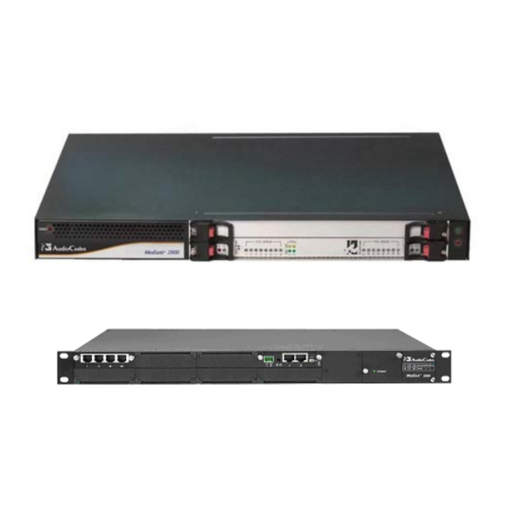
Page 35: V6100 Physical Description
8 E1/T-1 Spans. 8 RJ-48c trunk connectors V6100 Physical Description Designed to meet Network Equipment Building System (NEBS) Level 3, the V6100 is a 19- inch industrial platform chassis, 1U high and 13.8 inch deep. The V6100 supports a scalable, modular architecture that includes up to four modules, a... -
Page 36: V6100 Front Panel
V6100 Front Panel Figure 6 shows a front view of the V6100. Figure 6 V6100 Front View & CPU Enlargement Table 11 V6100 Front View Component Descriptions Item # Label Component Description Front View of Chassis 4 RJ-48c ports module. - Page 37 I/O Modules The V6100 supports up to four digital trunks (fully flexible, from a single and up to four trunks per module). If the power fails, a relay connects trunks 1 to 2 and 3 to 4 (in the same module) acting as a fallback for PSTN trunks.
- Page 38 / redundancy cannot occur. The front panel of the power supply unit features a power supply LED that is lit green when the V6100 is powered up. If this LED does not light up, a power supply problem may be present.
- Page 39 Fan Tray Module The V6100 components are cooled by a fan tray unit located to the extreme right, when facing the front panel (see Figure The fan tray unit draws air in by six fans through a perforated grill at the right side of the chassis.
- Page 40 Alternatively, if you are replacing the filter, discard the old air filter and replace it with an air filter purchased from 3Com. Attach the (new / cleaned) air filter to the fan try module; position the two holes on the...
- Page 41 Be sure to reinsert the fan tray unit while you are cleaning the air filter and reinsert the air filter as soon as it is clean. Front Panel LEDs Figure 10 shows the location of the front panel LEDs on the V6100. They are described in Table Table 13 Table...
-
Page 42: V6100 Rear Panel
Alarm Indication Signal (the Blue Alarm) Remote Alarm Indication (the Yellow Alarm) Either there is a failure / disruption in the AC power supply or the power is currently not being supplied to the V6100 through the AC power supply entry. Table 14... -
Page 43: V6100 Modules
Dual AC Power Supply Entry. 100-240v~1A Currently only the left-hand connector is active. Support for an active right-hand connector is intended in a future release. V6100 Modules The extractable V6100 modules are shown in Table Table 16 Extractable V6100 Modules Module... -
Page 44: V6100 Lifeline Phone Link
Power supply module V6100 Lifeline Phone Link The V6100 Digital with either one or two modules, each with 1 or 2 pairs of spans can provide a “Lifeline” telephone link. In the event of power failure, a link is provided by the closing of a metallic switch in the module so that the trunk from the PBX is routed out of the module to the PSTN. -
Page 45: Tp-260 Physical Description
Figure 12 V6100 Lifeline Phone Link The V6100 Digital with 4 modules each with 1 port, does NOT support the Lifeline. TP-260 Physical Description The TP-260 board is a fully ‘Plug and Play’ device. The PC’s boot-up sequence determines its I/O addresses and interrupts. -
Page 46: Tp-260 Leds
5 = Tx TIP body = shield TP-260 LEDs Table 18 through to Table 20 for LEDs. Table 18 Ethernet LEDs Label LED Color Function Yellow Receiving data Green Link Ethernet connection is ON (Link) V6100 and V7122 User Guide... - Page 47 OFF for half-duplex. Orange Link Transmit. When the PHY transmits, the LED toggles. RS-232 Internal use only. FAIL Indication from the TPM-1100. CLK40M When the LED toggles, the CLK40M for the PCI controller is active. V6100 and V7122 User Guide...
-
Page 48: Reader's Notes
Reader’s Notes V6100 and V7122 User Guide... -
Page 49: Chapter 3: Installation
(see TP-1610 Front Panel LED Indicators for details on the V7122 LEDs). When you have completed the above relevant sections you are then ready to start configuring the gateway ( C hapter 4: Getting Started). V6100 and V7122 User Guide... -
Page 50: Unpacking
Remove the V7122 gateway from the carton. Check that there is no equipment damage. Check, retain and process any documents. Notify 3Com or your local supplier of any damage or discrepancies Retain any diskettes or CDs. Package Contents Ensure that in addition to the V7122, the package contains: connection type) and one DC adaptor (screw connection type) connected to the rear panel of the V7122 are supplied;... -
Page 51: Mounting The V7122
Align a bracket over 2 holes on one side (so that the bracket’s larger holes face front) and with the 2 supplied replacement screws, screw in the bracket. Perform the same procedure on the other side. V6100 and V7122 User Guide... - Page 52 (of your choosing) in the vertical tracks of the 19-inch rack. Use standard 19-inch rack bolts (not provided) to fasten the device to the frame of the rack. 3Com recommends using two additional (not supplied) rear mounting brackets to provide added support. V6100 and V7122 User Guide...
-
Page 53: Cabling The V7122
Component Description RTM locking screws. ETHERNET Two Category 5 network cables, connected to the 2 Ethernet RJ-45 ports. TRUNKS Two 50-pin Telco connector cables, each supporting 8 trunks. Protective earthing screw. 100-240~1.5A Dual AC power cables. V6100 and V7122 User Guide... - Page 54 Install the Ethernet connection (see Installing the Ethernet Connection). Optionally, connect the V7122 RS-232 port to your PC (see Connecting the RS-232 Port to Your PC). Connect the power supply (see Connecting the Power Supply). V6100 and V7122 User Guide...
- Page 55 Connect the E1/T1 trunk cables to the ports labeled ’Trunks 1 to 8’ (in the case of the 8- trunk device) on the RTM. Connect the other ends of the Trunk cables to the PBX/PSTN switch. V6100 and V7122 User Guide...
- Page 56 RS-232 port to either COM1 or COM2 RS-232 communication port on your PC. The required connector pinout and gender are shown in Figure 23. For information on establishing a serial communications link with the gateway, see Establishing a Serial Communications Link with the V7122. V6100 and V7122 User Guide...
- Page 57 Each of the dual power cables can be connected to different AC power phases. Connecting the DC Power Supply To connect the V7122 to a DC power supply use one of these two options: DC Terminal block with a screw connection type. V6100 and V7122 User Guide...
- Page 58 Connect the two insulated wires to the correct DC power supply. Ensure that the connections to the DC power supply maintain the correct polarity (see Figure 25). Insert the terminal block into the DC inlet located on the V7122. V6100 and V7122 User Guide...
-
Page 59: Installing The Tp-1610
Install the TP-1610 in your PC (see Installing the TP-1610). Cable the TP-1610 (see Cabling the TP-1610). When you have completed the above relevant sections you are then ready to start configuring the gateway ( C hapter 4: Getting Started). V6100 and V7122 User Guide... -
Page 60: Unpacking
Remove the TP-1610 board from the carton. Check that there is no equipment damage. Check, retain and process any documents. Notify 3Com or your local supplier of any damage or discrepancies. Retain any diskettes or CDs. Package Contents Ensure that in addition to the TP-1610, the package contains: Optionally, an RTM module. - Page 61 Press the red ejector buttons on the two black ejector/injector latches on both ends and wait for the hot-swap blue LED to light, indicating that the board can be removed. Pull on the two ejector/injector latches and ease out the board from the slot. V6100 and V7122 User Guide...
-
Page 62: Cabling The Tp-1610
Cabling the V6100). After connecting the V6100 to the power source, the power LED on the front panel of the power supply unit is lit green (after a self-testing period of about 2 minutes). Any power supply malfunction results in the LED switching off (see... -
Page 63: Package Contents
Mounting the V6100 on a Desktop The integral front brackets are not required for a desktop installation. Optionally, attach the four (supplied) anti-slide bumpers to the base of the V6100 and place it on the desktop in the position you require. - Page 64 To place the V6100 on a 19-inch rack’s shelf: Place the V6100 on a preinstalled shelf. It is recommended to attach the V6100 integral front brackets to the frame of the rack to prevent it from sliding off the shelf during cabling. Use standard 19-inch rack bolts (not provided) to fasten the front of the V6100 to the frame of the rack.
-
Page 65: Cabling The V6100
Connect the first Ethernet connection (labeled I), located on the CPU module of the V6100 front panel, directly to the network using a standard RJ-45 Ethernet cable (and the second connection as optional redundancy / backup). Note that for redundant operation it is recommended to connect each of the Ethernet connectors to a different switch. - Page 66 Figure 28) connect the V6100 RS-232 port (Labeled I0I0) to either COM1 or COM2 RS-232 communication port on your PC. For information on establishing a serial communications link with the V6100, see Establishing a Serial Communications Link with the V7122.
- Page 67 Connect two additional wires into the mate’s spring-cage connections in position 2 and 1 (represented by label II in Figure 6) (see also Figure 29). During normal operation, dry contact labeled II is closed. If a malfunction occurs, dry contact labeled II opens. V6100 and V7122 User Guide...
-
Page 68: Installing The
To reduce the risk of damage due to electrostatic discharge when installing or servicing electronic equipment, it is recommended that anti-static earthing straps and mats be used. Not currently supported. Contact 3Com regarding availability. V6100 and V7122 User Guide... -
Page 69: Unpacking
Remove the TP-260 board from the carton. Check that there is no equipment damage. Check, retain and process any documents. Notify 3Com or your local supplier of any damage or discrepancies. Retain any diskettes or CDs. Package Contents Ensure that in addition to the TP-260, the package contains:... -
Page 70: Cabling The
(labeled 5/8) on each splitter supports each of the last four trunks. The TP-260 E1/T1 cable splitter is part of the 8-span TP-260 product and is PSTN certified. When using a non-3Com E1/T1 cable splitter, 3Com cannot guarantee compliance with PSTN homologations. Figure 31... - Page 71 14. Note that when assigning an IP address to the TP-260 using HTTP (under Step 1 in Assigning an IP Address Using HTTP), you may be required to disconnect this cable and re-cable it differently. V6100 and V7122 User Guide...
-
Page 72: Reader's Notes
Reader’s Notes V6100 and V7122 User Guide... -
Page 73: Chapter 4: Getting Started
Software Upgrade wizard, available through the Web Interface (see Software Upgrade Wizard), or alternatively use the BootP/TFTP configuration utility (see Upgrading the V7122). For information on the configuration files, see C hapter 16: Configuration Files. V6100 and V7122 User Guide... -
Page 74: Assigning The V7122 Ip Address
BootP/TFTP (Trivial File Transfer Protocol) configuration utility to access the device, ‘reflash’ the load and reset the password (see Appendix B : The BootP/TFTP Configuration Utility for detailed information on using a BootP/TFTP configuration utility to access the device). V6100 and V7122 User Guide... -
Page 75: Assigning An Ip Address Using Bootp
First access the CLI using a standard Telnet application or using a serial communication software (e.g., HyperTerminalTM) connected to the RS-232 port (if supported) (see A ccess CLI). Then assign the V7122 an IP address (see Assign an IP Address). V6100 and V7122 User Guide... - Page 76 Connect the RS-232 port to your PC (For the V7122, see Connecting the RS-232 Port to Your PC. For the V6100 see Connecting the V6100 RS-232 Port to Your PC). Use serial communication software (e.g., HyperTerminal ) to connect to the V7122.
-
Page 77: Configuring The V7122 Basic Parameters
To configure the V7122 basic parameters use the Embedded Web Server’s ‘Quick Setup’ screen (shown in Figure 32). See Accessing the Embedded Web Server for information on accessing the ‘Quick Setup’ screen. Figure 32 V7122 Quick Setup Screen V6100 and V7122 User Guide... - Page 78 You are now ready to start using the gateway. To prevent unauthorized access to the V7122, it is recommended that you change the username and password that are used to access the Web Interface. See Configuring the Web User Accounts for details on how to change the username and password. V6100 and V7122 User Guide...
- Page 79 VoIP gateway configuration (ini file) and store it in a directory on your PC. This saved file can be used to restore configuration settings at a future time. For information on backing up and restoring the gateway’s configuration, see Restoring and Backing up the Gateway Configuration. V6100 and V7122 User Guide...
-
Page 80: Reader's Notes
Reader’s Notes V6100 and V7122 User Guide... -
Page 81: Chapter 5: Web Management
Server). Secured HTTP connection (HTTPS) (see Embedded Web Server Configuration). Limiting access to a predefined list of IP addresses (see Configuring the Web and Telnet Access List). Managed access using a RADIUS server (see SRTP). V6100 and V7122 User Guide... -
Page 82: User Accounts
If the access level of the user is equal to or greater than the screen’s write access level, the screen can be modified. The default attributes for the two accounts are shown in Table V6100 and V7122 User Guide... -
Page 83: Limiting The Embedded Web Server To Read-Only Mode
Disabling the Embedded Web Server Access to the Embedded Web Server can be disabled by using the ini file parameter ‘DisableWebTask = 1’. The default is access enabled Accessing the Embedded Web Server To access the Embedded Web Server: V6100 and V7122 User Guide... -
Page 84: Using Internet Explorer To Access The Embedded Web Server
Prompt for username and password. b) Select the Advanced tab, scroll down until the HTTP 1.1 Settings are displayed and verify that the Use HTTP 1.1 option is checked. Restart the browser. V6100 and V7122 User Guide... -
Page 85: Getting Acquainted With The Web Interface
Submenu bar - appears on the top of screens and contains submenu options. Main action frame - the main area of the screen in which information is viewed and configured. Corporate logo – 3Com corporate logo. For information on how to remove this logo, see Customizing the V7122 Web Interface. -
Page 86: Saving Changes
The hyphen character is used in number entry only, as part of a range definition. For example, the entry [20-29] means ‘all numbers in the range 20 to 29’. V6100 and V7122 User Guide... -
Page 87: Protocol Management
Each coder can appear only once. From the Packetization Time drop-down list, select the packetization time (in msec) for the coder you selected. The packetization time determines how many coder payloads are combined into a single RTP packet. V6100 and V7122 User Guide... -
Page 88: Advanced Parameters
An exception to this logic is when the remote gateway is a Cisco device (IsCiscoSCEMode). Advanced Parameters Use this submenu to configure the following gateway’s advanced control protocol parameters: CDR and Debug Miscellaneous Parameters Supplementary Services V6100 and V7122 User Guide... -
Page 89: Number Manipulation Tables
Open the Number Manipulation screen you want to configure (Protocol Management menu > Manipulation Tables submenu); the relevant Manipulation table screen is displayed. Figure 36 shows the ‘Source Phone Number Manipulation Table for Tel IP calls’. V6100 and V7122 User Guide... - Page 90 Source IP address matches the IP address defined in the ‘Source IP’ field (if applicable). The number manipulation can be performed using a combination of each of the above criteria, or using each criterion independently. For available notations that represent multiple numbers, see Dialing Plan Notation. V6100 and V7122 User Guide...
- Page 91 Select the Number Plan assigned to this entry. You can select Unknown [0], Private [9] or E.164 Public [1]. The default is Unknown. For a detailed list of the available NPI/TON values, see Numbering Plans and Type of Number. V6100 and V7122 User Guide...
- Page 92 [2,3,4]xxx# represents four-digit numbers that start with 2, 3 or 4 54324 represents any number that starts with 54324 54324xx# represents a 7 digit number that starts with 54324 123[100-200]# represents all numbers from 123100 to 123200. V6100 and V7122 User Guide...
- Page 93 0/0 - Unknown/Unknown 1/1 - International number in ISDN/Telephony numbering plan 1/2 - National number in ISDN/Telephony numbering plan 1/4 - Subscriber (local) number in ISDN/Telephony numbering plan 9/4 - Subscriber (local) number in Private numbering plan V6100 and V7122 User Guide...
-
Page 94: Configuring The Routing Tables
(with a different IP address), or use an FQDN that resolves to two IP addresses. Call is sent to the alternative destination when one of the following occurs: V6100 and V7122 User Guide... - Page 95 In the ‘Routing Index' drop-down list, select the range of entries that you want to edit. Configure the Tel to IP Routing table according to Table Click the Submit button to save your changes. To save the changes so they are available after a power fail, see Save Configuration. V6100 and V7122 User Guide...
- Page 96 Ping Error = No ping to IP destination, route is not available QoS Low = Bad QoS of IP destination, route is not available DNS Error = No DNS resolution (only when domain name is used instead of an IP address). V6100 and V7122 User Guide...
- Page 97 To configure the IP to Trunk Group Routing table: Open the ‘IP to Trunk Group Routing’ screen (Protocol Management menu > Routing Tables submenu > IP to Trunk Group Routing option); the ‘IP to Trunk Group Routing’ table screen is displayed. V6100 and V7122 User Guide...
- Page 98 IP Tel call (obtained from the Contact header in the INVITE message). The source IP address can include the ‘x’ wildcard to represent single digits. For example: 10.8.8.xx represents all the addresses between 10.8.8.10 to 10.8.8.99. V6100 and V7122 User Guide...
- Page 99 In the ‘First IP Address’ field, enter the first IP address that the hostname is translated to. In the ‘Second IP Address’ field, enter the second IP address that the hostname is translated to. Repeat Steps 2 to 4, for each Internal DNS Table entry. V6100 and V7122 User Guide...
- Page 100 Open the ‘Reasons for Alternative Routing’ screen (Protocol Management menu > Routing Tables submenu > Reasons for Alternative Routing option); the ‘Reasons for Alternative Routing’ screen is displayed. Figure 40 Reasons for Alternative Routing Screen V6100 and V7122 User Guide...
-
Page 101: Configuring The Profile Definitions
Tel to IP and IP to Trunk Group Routing tables, or associate different Profiles to the gateway’s B-channels(s). The Profiles contain parameters such as Coders, T.38 Relay, Voice and DTMF Gains, Silence Suppression, Echo Canceler, RTP V6100 and V7122 User Guide... - Page 102 To configure the coder group settings: Open the ‘Coder Group Settings’ screen (Protocol Management menu > Profile Definitions submenu > Coder Group Settings option); the ‘Coder Group Settings’ screen is displayed. Figure 42 Coder Group Settings Screen V6100 and V7122 User Guide...
- Page 103 ‘annexb=no’ in the SDP of the relevant SIP messages. If silence suppression is set to ‘Enable w/o Adaptations’, ‘annexb=yes’ is included. An exception to this logic is when the remote gateway is a Cisco device (IsCiscoSCEMode). V6100 and V7122 User Guide...
- Page 104 (noted by an asterisk in the description of the parameter TelProfile_ID) of the preferred Profile are applied to that call. If the Preference of the Tel and IP Profiles is identical, the Tel Profile parameters are applied. V6100 and V7122 User Guide...
- Page 105 IP Profiles can also be used when working with Proxy server (set ‘AlwaysUseRouteTable’ to 1). To configure the IP Profile settings: Open the ‘IP Profile Settings’ screen (Protocol Management menu > Profile Definitions submenu > IP Profile Settings option); the ‘IP Profile Settings’ screen is displayed. V6100 and V7122 User Guide...
- Page 106 Configure the Profile’s parameters according to your requirements. For detailed information on each parameter see the description of the screen in which it is configured as an individual parameter. V6100 and V7122 User Guide...
-
Page 107: Configuring The Trunk Group Table
For example, enter [1-24] to specify the channels from 1 to 24. The number of defined channels must not exceed the number of the trunk’s B-channels (1-24 for T1 spans and 1-31 for E1 spans). To represent all B-channels use a single asterisk instead. V6100 and V7122 User Guide... -
Page 108: Configuring The Trunk Group Settings
Trunk group), the global rule, defined by the Channel Select Mode parameter (Protocol Definition > General Parameters), applies. To configure the Trunk Group Settings table: Open the ‘Trunk Group Settings’ screen (Protocol Management menu > Trunk Group Settings); the ‘Trunk Group Settings’ screen is displayed. V6100 and V7122 User Guide... - Page 109 Trunk Group and then starts ascending again (default). Ascending Select the lowest available channel. Always start at the lowest channel number in the Trunk Group and if that channel is not available, select the next higher channel. V6100 and V7122 User Guide...
-
Page 110: Advanced Configuration
OSs, and network architectures. Up to five different NFS file systems can be configured. NFS is utilized by the V7122 to load the cmp, ini and configuration files via the Automatic Update mechanism (see Automatic Update Mechanism). V6100 and V7122 User Guide... - Page 111 To save the changes so they are available after a power fail, see Save Configuration. To avoid terminating calls in progress, a row must not be deleted or modified while the board is currently accessing files on that remote NFS file system. V6100 and V7122 User Guide...
- Page 112 Settings>IP Settings screen). Up to 50 routing entries are available. To configure the IP Routing table: Open the ‘IP Routing Table’ screen (Advanced Configuration menu > Network Settings > IP Routing Table option); the ‘IP Routing Table’ screen is displayed. V6100 and V7122 User Guide...
- Page 113 A read-only field that indicates the time period for which the specific routing rule is valid. The lifetime of a static route is infinite. Hop Count The maximum number of allowed routers between the gateway and destination. V6100 and V7122 User Guide...
-
Page 114: Configuring The Media Settings
Initially, the screen appears with the parameters fields grayed (indicating read-only). The Stop Trunk button appears at the bottom of the screen. The Trunk Status indicators appear colored. Table 36 shows the possible indicators and their descriptions. V6100 and V7122 User Guide... - Page 115 Trunk’s Status indicator. The first parameter named ‘Trunk ID’ changes according to the trunk you click. The parameters displayed are for the selected trunk only. V6100 and V7122 User Guide...
- Page 116 Click the arrow button (-->) to the right of the relevant behavior parameter; a new window appears. b) Modify each bit field according to your requirements. c) Click the Submit button to save your changes. V6100 and V7122 User Guide...
-
Page 117: Configuring Ss7 Tunneling
For a detailed description of M2P2 attributes, see SS7 Parameter Tables. To configure the M2P2 Attributes parameters: Open the ‘M2P2 Attributes‘ screen (Advanced Configuration menu > SS7 Configuration > M2P2 Attributes option); the ‘M2P2 Attributes’ screen is displayed. V6100 and V7122 User Guide... - Page 118 Configuring Links For a detailed description of Links, see SS7 Parameter Tables. To configure the Links parameters: Open the ‘Links‘ screen (Advanced Configuration menu > SS7 Configuration > Links option); the ‘Links’ screen is displayed. V6100 and V7122 User Guide...
- Page 119 For a detailed description of Sigtran Group IDs, see SS7 Parameter Tables. To configure the Sigtran Group IDs parameters: Open the ‘Sigtran Group IDs‘ screen (Advanced Configuration menu > SS7 Configuration > Sigtran Group IDs option); the ‘Sigtran Group IDs‘ screen is displayed. V6100 and V7122 User Guide...
- Page 120 To configure the Sigtran Interface IDs parameters see SS7 Parameter Tables. Open the ‘Sigtran Interface IDs‘ screen (Advanced Configuration menu > SS7 Configuration > Sigtran Interface IDs option); the ‘Sigtran Interface IDs‘ screen is displayed. V6100 and V7122 User Guide...
-
Page 121: Configuring The Tdm Bus Settings
Click the Submit button to save your changes. To save the changes so they are available after a power fail, see Save Configuration. A device reset is required to activate the TDM Bus Settings parameters. To reset the V7122, see Save Configuration. V6100 and V7122 User Guide... -
Page 122: Restoring And Backing Up The Gateway Configuration
VoIP gateway information stored on your computer. To restore or back up the ini file: Open the ‘Configuration File’ screen (Advanced Configuration menu > Configuration File); the ‘Configuration File’ screen is displayed. V6100 and V7122 User Guide... -
Page 123: Regional Settings
Voice Prompts. For detailed information on the configuration files, see C hapter 16: Configuration Files. To configure the date and time of the V7122: Open the ‘Regional Settings’ screen (Advanced Configuration menu > Regional Settings); the ‘Regional Settings' screen is displayed. V6100 and V7122 User Guide... - Page 124 A device reset is required to activate a loaded CPT file. To save the loaded auxiliary files so they are available after a power fail, see Save Configuration. To reset the V7122, see Save Configuration. V6100 and V7122 User Guide...
-
Page 125: Security Settings
Embedded Web Server. To change the Web User Accounts attributes: Open the ‘Web User Accounts’ screen (Advanced Configuration menu > Security Settings > Web User Accounts option); the ‘Web User Accounts’ screen is displayed. V6100 and V7122 User Guide... - Page 126 19 case-sensitive characters. A user with a ‘Security Administrator’ access level can change all attributes for all accounts. Users with an access level other than ‘Security Administrator’ can only change their own password and username. V6100 and V7122 User Guide...
- Page 127 Configuring the Firewall Settings The V7122 accommodates an internal Firewall, allowing the security administrator to define network traffic filtering rules. For detailed information on the internal Firewall, see Internal Firewall. V6100 and V7122 User Guide...
- Page 128 Click the radio button of the entry you want to activate. Click the Activate Rule button; the rule is active. To de-activate an activate rule: Click the radio button of the entry you want to activate. V6100 and V7122 User Guide...
-
Page 129: Configuring The Management Settings
Open the SNMP Managers Table screen by clicking the arrow sign (-->) to the right of the SNMP Managers Table label; the SNMP Managers Table screen is displayed (Figure 61). Configure the SNMP manager’s parameters. V6100 and V7122 User Guide... - Page 130 SNMP Community Strings label; the SNMP Community Strings screen is displayed (Figure 62). Configure the SNMP Community Strings parameters according to Table Click the Submit button to save your changes. To save the changes so they are available after a power fail, see Save Configuration. V6100 and V7122 User Guide...
-
Page 131: Status & Diagnostic
IP Connectivity The IP Connectivity screen provides you with an online read-only network diagnostic connectivity information on all destination IP addresses configured in the Tel to IP Routing table. V6100 and V7122 User Guide... - Page 132 Host name (or IP address) defined in the destination IP address field in the Tel to IP Routing table. Connectivity The method according to which the destination IP address is queried periodically (currently Method only by ping). V6100 and V7122 User Guide...
- Page 133 The release reason can be viewed in the Termination Reason field in the CDR message. For detailed information on each counter, see Table You can reset this information by clicking the Reset Counters button. V6100 and V7122 User Guide...
- Page 134 This counter indicates the number of calls that failed as a result of a busy line. It is Failed Calls due incremented as a result of the following release reason: to a Busy Line GWAPP_USER_BUSY (17) V6100 and V7122 User Guide...
- Page 135 The Call Routing Status screen provides you with information on the current routing method used by the gateway. This information includes the IP address and FQDN (if used) of the Proxy server the gateway currently operates with. Figure 65 Call Routing Status Screen V6100 and V7122 User Guide...
-
Page 136: Monitoring The V7122 Trunks & Channels
To monitor the status of the trunks and B-channels follow this step: Open the ‘Trunk & Channel Status’ screen (Status & Diagnostics menu > Channel Status); the ‘Trunk & Channel Status’ screen is displayed. Figure 66 V7122 Trunk & Channel Status Screen V6100 and V7122 User Guide... - Page 137 Click the numbered icon of the specific channel whose detailed status you need to check/monitor; the channel-specific Channel Status screen appears, shown in Figure Click the submenu links to check/view a specific channel’s parameter settings. V6100 and V7122 User Guide...
-
Page 138: Activating The Internal Syslog Viewer
Syslog logging level, in the range 0 to 5, where 5 is the highest level. Open the ‘Message Log’ screen (Status & Diagnostics menu > Message Log); the ‘Message Log’ screen is displayed and the Log is activated. V6100 and V7122 User Guide... -
Page 139: Device Information
From this screen you can also view and remove any loaded files used by the V7122 (stored in the RAM). To access the Device Information screen: Open the ‘Device Information’ screen (Status & Diagnostics menu > Device Information); the ‘Device Information’ screen is displayed. V6100 and V7122 User Guide... -
Page 140: Viewing The Ethernet Port Information
Redundancy. For detailed information on the Ethernet interface configuration, see Ethernet Interface Configuration. To view the Ethernet Port Information parameters: Open the ‘Ethernet Port Information’ screen (Advanced Configuration menu > Network Settings > Ethernet Port Information option); the ‘Ethernet Port Information’ screen is displayed. V6100 and V7122 User Guide... -
Page 141: Front Panel View (V6100 Only)
Shows the speed, in Mbps, that Ethernet port 2 is using (10 Mbps or 100 Mbps). Front Panel View (V6100 Only) The Front Panel View screen displays the configuration of the V6100 in real time (the number of installed modules and the number of trunks on each module). For information on the trunk’s status indicators, see... -
Page 142: Software Update Menu
Figure 72 V6100 Front Panel View Screen Software Update Menu The ‘Software Update’ menu enables users to upgrade the V7122 software by loading a new cmp file along with the ini and a suite of auxiliary files, or to update the existing auxiliary files. - Page 143 (Figure 74). When in the Wizard process, the rest of the Web application is unavailable and the background Web screen is disabled. After the process is completed, access to the full Web application is restored. V6100 and V7122 User Guide...
- Page 144 Click Back; the ‘Load a cmp File’ screen is reverted to; see Figure d) Click Next; the ‘Load an ini File’ screen opens; see Figure 76. Loading a new ini file or any other auxiliary file listed in the Wizard is optional. V6100 and V7122 User Guide...
- Page 145 Click Back; the ‘Load a cmp file’ screen is reverted to; see Figure d) Click Next; the ‘Load a CPT File’ screen opens (see Figure 77); Loading a new CPT file or any other auxiliary file listed in the Wizard is optional. V6100 and V7122 User Guide...
- Page 146 ‘End Process’ screen appears displaying the burned configuration files (see Figure 79). b) Click Cancel, the V7122 resets, utilizing the files previously stored in flash memory. (Note that these are NOT the files you loaded in the previous Wizard steps). Figure 78 FINISH Screen V6100 and V7122 User Guide...
-
Page 147: Auxiliary Files
PBX extensions as IP phones in the global ‘IP world’. To load an auxiliary file to the gateway: Open the ‘Auxiliary Files’ screen (Software Upgrade menu > Load Auxiliary Files); the ‘Auxiliary Files’ screen is displayed. V6100 and V7122 User Guide... - Page 148 A device reset is required to activate a loaded CPT file, and may be required for the activation of certain ini file parameters. To save the loaded auxiliary files so they are available after a power fail, see Save Configuration. To reset the V7122, see Save Configuration. V6100 and V7122 User Guide...
-
Page 149: Updating The Software Upgrade Key
To save the changes to the non-volatile: Click the Save Configuration button on the main menu bar; the ‘Save Configuration’ screen is displayed. Figure 81 Save Configuration Screen V6100 and V7122 User Guide... -
Page 150: Resetting The V7122
For detailed information on the Web User Accounts, see User Accounts. To log off the Embedded Web Server: Click the Log Off button on the main menu bar; the Log Off prompt screen is displayed. V6100 and V7122 User Guide... - Page 151 Figure 83 Log off Prompt Click OK in the prompt; the Web session is logged off. V6100 and V7122 User Guide...
-
Page 152: Reader's Notes
Reader’s Notes V6100 and V7122 User Guide... -
Page 153: Chapter 6: Ini File Configuration Of The V7122
Restoring and Backing up the Gateway Configuration). Open the file (the file opens in Notepad or a Customer-defined text file editor) and modify the ini file parameters according to your requirements. Save and close the file. V6100 and V7122 User Guide... -
Page 154: The Ini File Content
53, parameters in brackets are the format in the Embedded Web Server. The ini File Structure The ini file can contain any number of parameters. The parameters are divided into groups by their functionality. The general form of the ini file is shown in Figure V6100 and V7122 User Guide... -
Page 155: The Ini File Structure Rules
The parameter name is NOT case-sensitive; the parameter value is NOT case-sensitive except for coder names. The ini file should be ended with one or more carriage returns. The ini File Example Figure 85 shows an example of an ini file for the VoIP gateway. V6100 and V7122 User Guide... -
Page 156: Networking Parameters
EthernetPhyConfiguration 0 = 10 Base-T half-duplex 1 = 10 Base-T full-duplex 2 = 100 Base-TX half-duplex 3 = 100 Base-TX full-duplex 4 = auto-negotiate (default) For detailed information on Ethernet interface configuration, Ethernet Interface Configuration. V6100 and V7122 User Guide... - Page 157 If the domain name isn’t found, the gateway performs a DNS resolution using an external DNS server. This parameter can appear up to 10 times. V6100 and V7122 User Guide...
- Page 158 The compare operation that is performed on the IP address is enabled by default and is controlled by the parameter ‘EnableIPAddrTranslation’. The compare operation that is performed on the UDP port is disabled by default and is controlled by the parameter ‘EnableUDPPortTranslation’. V6100 and V7122 User Guide...
- Page 159 UDP port of the outgoing stream is replaced by the source UDP port of the first incoming packet. The NAT mechanism and the IP address translation must be enabled for this parameter to take effect (DisableNAT = 0, EnableIpAddrTranslation = 1). V6100 and V7122 User Guide...
- Page 160 6012, etc. If RTP Base UDP Port is not a factor of 10, the following message is generated: ‘invalid local RTP port’. For detailed information on the default RTP/RTCP/T.38 port allocation, see Default RTP/RTCP/T.38 Port Allocation. V6100 and V7122 User Guide...
- Page 161 IP address (in dotted format notation) of the NTP server. [NTP Server IP Address] The default IP address is 0.0.0.0 (the internal NTP client is disabled). For information on NTP support, see Simple Network Time Protocol Support. V6100 and V7122 User Guide...
- Page 162 VLAN identifier. The valid range is 1 to 4094. The default value is 1. VlanControlVlanID Sets the control VLAN identifier. [Control VLAN ID] The valid range is 1 to 4094. The default value is 2. V6100 and V7122 User Guide...
- Page 163 The gateway’s subnet mask in the Media network. [Subnet Mask] The default subnet mask is 0.0.0.0. LocalMediaDefaultGW The gateway’s default gateway IP address in the Media [Default Gateway Address] network. The default value is 0.0.0.0. V6100 and V7122 User Guide...
- Page 164 The default value is 0.0.0.0. PPPoERecoverIPAddress IP address to use when booting from the flash to non-PPPoE (Point-to-Point Protocol over Ethernet) environments. The valid IP address range is in dotted notation xxx.xxx.xxx.xxx. The default value is 10.4.10.4. V6100 and V7122 User Guide...
- Page 165 The domain name or IP address of the NFS server. If a [Host / IP] domain name is provided, a DNS server must be configured. Path to the root of the remote file system. NFSServers_RootPath In the format: ‘/’ + [path] [Root Path] For example, /audio V6100 and V7122 User Guide...
- Page 166 The valid range is 0 to 65535. When filtering fragmented IP packets, the Packet Size field relates to the overall (reassembled) packet size, not to the size of each fragment. AccessList_Byte_Rate Expected traffic rate (bytes per second). [Byte Rate] V6100 and V7122 User Guide...
- Page 167 Tolerance of traffic rate limit (number of bytes) Burst Bytes AccessList_Allow_Type Action upon match (allow or block) [Action Upon Match] AccessList_MatchCount A read-only field that provides the number of packets [Match Count] accepted / rejected by a specific rule. V6100 and V7122 User Guide...
-
Page 168: System Parameters
SPC (Sensitive Parameters Value Change) - Changes made to sensitive parameters: (1) IP Address (2) Subnet Mask (3) Default Gateway IP Address (4) ActivityListToLog For example: ActivityListToLog = 'pvc', 'afl', 'dr', 'fb', 'swu', 'ard', 'naa', 'spc' V6100 and V7122 User Guide... - Page 169 The CDR messages are sent to UDP port 514 (default Syslog port). HeartBeatDestIP Destination IP address (in dotted format notation) to which the gateway sends proprietary UDP ‘ping’ packets. The default IP address is 0.0.0.0. V6100 and V7122 User Guide...
- Page 170 RTP packets. To overcome this issue, set ‘DisconnectOnBrokenConnection=0’; the gateway doesn’t detect RTP packets arriving from the original source IP address, and switches (after 300 msec) to the RTP packets arriving from the new source IP address. V6100 and V7122 User Guide...
- Page 171 The cmp file is validated before it is burned to flash. The checksum of the cmp file is also compared to the previously-burnt checksum to avoid unnecessary resets. V6100 and V7122 User Guide...
- Page 172 This option can be used to activate offline (not on-the-fly) parameters that are loaded via IniFileUrl. 0 = The immediate restart mechanism is disabled (default). 1 = The gateway immediately restarts after an ini file with this parameter set to 1 is loaded. V6100 and V7122 User Guide...
- Page 173 1 = 1 second (default). 2 = 3 second. 3 = 6 second. 4 = 30 second. 5 = 60 second. This parameter only takes effect from the next reset of the device. V6100 and V7122 User Guide...
-
Page 174: Web And Telnet Parameters
1 = Password and username are reset (for the default username and password, see Table 26). The username and password cannot be reset from the Web (i.e., via AdminPage or by loading an ini file). V6100 and V7122 User Guide... - Page 175 Name of the image file containing the user’s logo. File name can be up to 47 characters. The logo file name can be used to replace 3Com’ default Web logo with a user defined logo. Use a gif, jpeg or jpg image file.
-
Page 176: Security Parameters
Secure Hypertext Transport Protocol (HTTPS) Parameters HTTPSOnly Determines the protocol types used to access the Embedded Web Server. [Secured Web Connection] 0 = HTTP and HTTPS (default). 1 = HTTPS only (unencrypted HTTP packets are blocked). V6100 and V7122 User Guide... - Page 177 The destination UDP/TCP ports (on this device) to which packets are sent. AccessList_End_Port The valid range is 0 to 65535. [Local Port Range] When the protocol type isn’t TCP or UDP, the entire range must be provided. V6100 and V7122 User Guide...
- Page 178 Tolerance of traffic rate limit (number of bytes) [Burst Bytes] AccessList_Allow_Type Action upon match (allow or block) [Action Upon Match] AccessList_MatchCount A read-only field that provides the number of packets accepted / rejected by a [Match Count] specific rule. V6100 and V7122 User Guide...
-
Page 179: Radius Parameters
Defines the default access level for the gateway when the RADIUS [Default Access Level] (authentication) response doesn’t include an access level attribute. The valid range is 0 to 255. The default value is 200 (Security Administrator'). V6100 and V7122 User Guide... -
Page 180: Snmp Parameters
Up to five IP addresses of remote trusted SNMP managers from which the SNMP agent accepts and processes get and set requests. If no values are assigned to these parameters any manager can access the device. Trusted managers can work with all community strings. V6100 and V7122 User Guide... - Page 181 Up to five read / write community strings (up to 19 characters each). The default string is ‘private’. [SNMP Community Strings Table] SNMPTrapCommunityString Community string used in traps (up to 19 characters). [SNMP Community Strings Table] The default string is ‘trapuser’. V6100 and V7122 User Guide...
-
Page 182: Sip Configuration Parameters
SIP URI, in the From header. If not specified, the gateway IP address is used instead (default). IsProxyUsed 0 = Proxy isn’t used, the internal routing table is used instead (default). [Enable Proxy] 1 = Proxy is used. V6100 and V7122 User Guide... - Page 183 ProxyName Home Proxy Domain Name. If specified, the name is used as Request-URI [Proxy Name] in REGISTER, INVITE and other SIP messages. If the proxy name isn’t specified, the Proxy IP address is used instead. V6100 and V7122 User Guide...
- Page 184 Contact header in 30x response) (default). 1 = All INVITE messages, including those generated as a result of Transfer or Redirect are sent to Proxy. Applicable only if Proxy server is used and ‘AlwaysSendtoProxy=0’. V6100 and V7122 User Guide...
- Page 185 UserAgentDisplayInfo Defines the string that is used in the SIP request header ‘User-Agent’ and [User-Agent Information] SIP response header ‘Server’. If not configured, the default string ‘3Com product-name s/w-version’ is used (e.g., User-Agent: 3Com-Sip-Gateway- V7122/v.4.80.004.008). When configured, the string ‘UserAgentDisplayInfo s/w-version’...
- Page 186 To enable the redundant Proxies mechanism set ‘EnableProxyKeepAlive’ to 1 or 2. UserName Username used for Registration and for Basic/Digest authentication [User Name] process with Proxy / Registrar. Parameter doesn’t have a default value (empty string). V6100 and V7122 User Guide...
- Page 187 Keep-Alive messages when EnableProxyKeepAlive = 2 (REGISTER). Typically a value of 3600 is assigned, for one hour registration. The gateway resumes registration according to the parameter RegistrationTimeDivider. The default is 3600 seconds. V6100 and V7122 User Guide...
- Page 188 1 = RPI headers are generated in SIP INVITE messages for both called and calling numbers. IsUserPhone 0 = Doesn’t use ‘user=phone’ string in SIP URI. [Use “user=phone” in SIP 1 = ‘user=phone’ string is part of the SIP URI (default). URL] V6100 and V7122 User Guide...
- Page 189 30 (default), 60, Disable [0] 6.3 [1] Always 4 [g7231] 90, 120 Enable [1] (default) 10, 20 (default), G.726 Disable [0] 30, 40, 50, 60, Always 32 Always 2 [g726] Enable [1] 80, 100, 120 V6100 and V7122 User Guide...
- Page 190 Disable [0] Always 0 [Evrc] 60, 80, 100 120) Enable [1] Transpar 20 (default), 40, Dynamic (0- Disable [0] Always 64 [Transpar 60, 80, 100, 120 120) Enable [1] ent] Doesn’t apply to the V6100. V6100 and V7122 User Guide...
- Page 191 Obsolete parameter, use CoderName instead. TransparentPayloadType Obsolete parameter, use CoderName instead. DSPVersionTemplateNumb Determines the number of the DSP load (doesn’t apply to the V6100). Each load has a different coder list, a different channel capacity and different [DSP Version Template supported features.
- Page 192 When ‘IsFaxUsed’ is set to 1, 2 or 3 the parameter ‘FaxTransportMode’ is ignored. When the value of IsFaxUsed is other than 1, T.38 might still be used without the control protocol’s involvement. To completely disable T.38, set FaxTransportMode to a value other than 1. V6100 and V7122 User Guide...
- Page 193 The valid range is 10 to 100000. The default value is 90. SIPMaxRtx Number of UDP transmissions (first transmission + retransmissions) of SIP [SIP Maximum Rtx] messages. The range is 1 to 7. The default value is 7. V6100 and V7122 User Guide...
- Page 194 EnableHold 0 = Hold service is disabled. [Enable Hold] 1 = Hold service is enabled, held tone is played to holding party (default). V6100 and V7122 User Guide...
- Page 195 SDP. However some gateways use the absence of the ‘telephony-event’ from the SDP to decide to send DTMF digits inband using G.711 coder, if this is the case you can set ‘RxDTMFOption=0’. V6100 and V7122 User Guide...
- Page 196 The DTMF transmit methods are defined using a repetition of the same (TxDTMFOption) parameter (up to five options can be provided). IsDTMFUsed Obsolete parameter, use TxDTMFOption instead. [Use Out-of-Band DTMF] OutOfBandDTMFFormat Obsolete parameter, use TxDTMFOption instead. [Out-of-Band DTMF Format] V6100 and V7122 User Guide...
- Page 197 (# of ‘p’ * 1.5 seconds) and then sends the rest of the DTMF digits using the method chosen (in-band, out-of-band). The called number can include several ‘p’ characters (1.5 seconds pause). For example, the called number can be as follows: 1001pp699, 8888p9p300. V6100 and V7122 User Guide...
- Page 198 (default) 10, 20 (default), G.726 Always Disable [0] 30, 40, 50, 60, 80, Always 2 [g726] Enable [1] 100, 120 GSM-FR 20 (default), 40, Always Disable [0] gsmFull Always 3 60, 80 Enable [1] Rate V6100 and V7122 User Guide...
- Page 199 20 (default), 40, Dynamic Disable [0] Always 0 [Evrc] 60, 80, 100 (0-120) Enable [1] Transpar 20 (default), 40, Always Dynamic Disable [0] [Transpar 60, 80, 100, 120 (0-120) Enable [1] ent] Doesn’t apply to the V6100. V6100 and V7122 User Guide...
- Page 200 Therefore, it is highly recommended not to select both coders simultaneously. This parameter (CoderName_ID) can appear up to 20 times (five coders in four coder groups). For example: CoderName_1 = g711Alaw64k,20,,,0 CoderName_1 = g711Ulaw64k,40 CoderName_1 = g7231,90,1,,1 CoderName_2 = g726,$$,2,,0 V6100 and V7122 User Guide...
- Page 201 The IP ProfileID can be used in the Tel2IP and IP2Tel routing tables (Prefix and PSTNPrefix parameters). ‘Profile Name’ assigned to a ProfileID, enabling user to identify it intuitively and easily. This parameter can appear up to 9 times (ID = 1 to 9). V6100 and V7122 User Guide...
-
Page 202: Voice Mail Parameters
This parameter can appear up to 4 times (ID = 1 to 4). Voice Mail Parameters The Voice Mail (VM) application applies only to the V6100 and V7122. For detailed information on VM, see the CPE Configuration Guide for Voice Mail. - Page 203 The valid range is a 120-character string. Digit Pattern] DigitPatternForwardOnD Determines the digit pattern used by the PBX to indicate ‘call forward on do not disturb’. [Forward on Do Not The valid range is a 120-character string. Disturb Digit Pattern] V6100 and V7122 User Guide...
-
Page 204: Isdn And Cas Interworking-Related Parameters
IP to Trunk Group routing table is used to define the destination IP address of the terminating V7122. The terminating V7122 gateway automatically answers these calls if its E1/T1 protocol is set to ‘Transparent’ (ProtocolType = 5). V6100 and V7122 User Guide... - Page 205 SIP messages using a dedicated message body. Note that QSIG tunneling must be enabled on both the originating and terminating gateways. It is necessary to set the parameter ‘ISDNDuplicateQ931BuffMode’ to 128 (duplicate all messages) so that this mechanism can function. V6100 and V7122 User Guide...
- Page 206 Determines the method used to play Ringback tone to the Tel side. [Play Ringback Tone to It applies to all trunks that are not configured by the parameter Tel] PlayRBTone2Trunk. Similar description as the parameter ‘PlayRBTone2Trunk’. V6100 and V7122 User Guide...
- Page 207 If the Q.850 Release Cause is found, the SIP response assigned to it is sent to the IP side. If no match is found, the default static mapping is used. For example: CauseMapISDN2SIP=6,406 This parameter can appear up to 12 times. V6100 and V7122 User Guide...
- Page 208 PI in the Disconnect message, the call is released (default). 0 = Do not send a 183 message to IP. The call is released. 1, 8 = Sends 183 message to IP. PIForDisconnectMsg [Set PI in Rx Disconnect Obsolete parameter, use PIForDisconnectMsg_ID instead. Message] V6100 and V7122 User Guide...
- Page 209 Usually, the gateway requests the PBX to connect an incoming and an outgoing call. This parameter determines if the outgoing call (from the gateway to the PBX) must be connected before the transfer is initiated. V6100 and V7122 User Guide...
- Page 210 (Disconnect or Release messages). The gateway converts the AOC messages into SIP INFO (during a call) and BYE (end of a call) messages using a proprietary AOC SIP header. The gateway supports both Currency and Pulse AOC messages. V6100 and V7122 User Guide...
- Page 211 To activate this feature set the parameter ‘EnableDSPIPMDetectors’ to 1. Usually this feature is used only when early media is used to establish voice path before the call is answered. This feature is applicable only when the protocol type is CAS. V6100 and V7122 User Guide...
- Page 212 The valid range is 10 to 240. The default value is 50. Applicable only to Japan NTT PRI variant (ProtocolType = 16). This timer is also affected by the parameter ‘PSTNAlertTimeout’. V6100 and V7122 User Guide...
-
Page 213: Number Manipulation And Routing Parameters
For T1 CAS signaling: 0 to 23 for first span, 24 to 47 for second span, 48 to 71 for 3 span, and 72 to 95 for 4 span. It is suggested to use Trunk Groups in V7122 gateway to define enabled B- channels, instead of ChannelList parameter. V6100 and V7122 User Guide... - Page 214 1 = Add trunk ID number (single digit in the range 1 to 8) as a prefix to the called phone number for Tel IP incoming calls. This option can be used to define various routing rules. V6100 and V7122 User Guide...
- Page 215 Source Number and Display Name are set to ’100’ and the Presentation is set to Allowed (0). When the following is received ‘from: <sip:100@101.102.103.104>’, the outgoing Source Number is set to ‘100’ and the Presentation is set to Restricted (1). V6100 and V7122 User Guide...
- Page 216 An optional IP ProfileID (1 to 4) can be applied to each routing rule. The Source IP Address can include the ‘x’ wildcard to represent single digits. For example: 10.8.8.xx represents all IP addresses between 10.8.8.10 to 10.8.8.99. V6100 and V7122 User Guide...
- Page 217 The ‘b’ to ‘f’ manipulations rules are applied if the called and calling numbers match the ‘a’ and ‘g’ conditions. The manipulation rules are executed in the following order: ‘b’, ‘d’ and ‘c’. Parameters can be skipped by using the sign ‘$$’, for example: NumberMapTel2IP=01,2,972,$$,0,0,$$ NumberMapTel2IP=03,(2),667,$$,0,0,22 V6100 and V7122 User Guide...
- Page 218 The ‘b’ to ‘f’ and ‘h’ manipulation rules are applied if the called and calling numbers match the ‘a’ and ‘g’ conditions. The manipulation rules are executed in the following order: ‘b’, ‘d’ and ‘c’. Parameters can be skipped by using the sign ‘$$’, for example: SourceNumberMapTel2IP=01,2,972,$$,0,0,$$,1 SourceNumberMapTel2IP=03,(2),667,$$,0,0,22,0 V6100 and V7122 User Guide...
- Page 219 0/0 - Unknown/Unknown 1/1 - International number in ISDN/Telephony numbering plan 1/2 - National number in ISDN/Telephony numbering plan 1/4 - Subscriber (local) number in ISDN/Telephony numbering plan 9/4 - Subscriber (local) number in Private numbering plan V6100 and V7122 User Guide...
- Page 220 Restriction routing rule, IP=0.0.0.0, is applied), the call is released. Alternative Routing Parameters AltRoutingTel2IPEnable Operation modes of the Alternative Routing mechanism: [Enable Alt Routing Tel to IP] 0 = Disabled (default). 1 = Enabled. 2 = Enabled for status only, not for routing decisions. V6100 and V7122 User Guide...
-
Page 221: E1/T1 Configuration Parameters
Web Parameter Name TDMBusType TP-260 only. Must be set to 2. PCMLawSelect 1 = A-law 3 = μ-Law [PCM Law Select] Usually A-Law is used for E1 spans and μ-Law for T1 and J1 spans. V6100 and V7122 User Guide... - Page 222 Select ‘User Side’ when the PSTN or PBX side is configured as ‘Network side’, and vice-versa. If you don’t know the V7122 ISDN termination side, choose ‘User Side’ and see the ‘Status & Diagnostics>Channel Status’ screen. If the D-channel alarm is indicated, choose ‘Network Side’. V6100 and V7122 User Guide...
- Page 223 ‘x’ identifies the Trunk ID (0-7). Trunks that belong to the same NFAS group have the same number. With ISDN Non-Facility Associated Signaling you can use single D-channel to control multiple PRI interfaces. Applicable only to T1 ISDN protocols. V6100 and V7122 User Guide...
- Page 224 Set to -1 for default. IdlePCMPattern Range 0x00 to 0xFF Default = -1 (default pattern = 0xFF for μ-Law, 0x55 for A-law [Idle PCM Pattern] PCM Pattern to be applied to E1/T1 timeslot (B-channel) when the channel is idle. V6100 and V7122 User Guide...
- Page 225 (including the ‘Sending Complete’ Info Element) was fully received (via SETUP and/or subsequent INFO Q.931 messages). The ‘MaxDigits’ parameter can be used to limit the length of the collected number for V7122 ISDN overlap dialing (if sending complete was not received). V6100 and V7122 User Guide...
- Page 226 Resume (Reanswer) signal once a Suspend (Clear back) signal was received from the PBX. If this timer expires, the call is released. The valid range is 0 to 255. The default value is 0. Applicable only for MFC R2 CAS Brazil variant. V6100 and V7122 User Guide...
- Page 227 Q.931 Setup for incoming Tel IP calls. To configure the gateway to support several ‘ISDNInCallsBehavior’ features, summarize the individual feature values. For example to support both ‘2048’ and ‘65536’ features, set ‘ISDNInCallsBehavior = 67584. V6100 and V7122 User Guide...
- Page 228 131072 = Clears the call on reception of Q.931 Status with incompatible state. Otherwise, (default) no action is taken. To configure the gateway to support several ‘ISDNIBehavior’ features, summarize the individual feature values. For example to support both ‘512’ and ‘2048’ features, set ‘ISDNIBehavior = 2560’. V6100 and V7122 User Guide...
-
Page 229: Channel Parameters
Modem Transport Modes for a detailed description of Fax and Modem transfer modes; see Configuring the DTMF Transport Types for detailed description on DTMF transport modes. The Default Channel Parameters are applied to all V7122 channels. V6100 and V7122 User Guide... - Page 230 Coder the gateway uses when performing fax/modem bypass. Usually, [Fax/Modem Bypass Coder Type] high-bit-rate coders such as G.711 should be used. You can select: 0 = G.711 A-law 64 (default). 1 = G.711 μ-law. 4 = G.726 32. 11 = G.726 40. V6100 and V7122 User Guide...
- Page 231 0 to 150 msec (default=40) Determines the Jitter Buffer delay during fax and modem bypass session BellModemTransportType Determines the Bell modem transport method. 0 = Transparent (default). 2 = Bypass. 3 = Transparent with events. V6100 and V7122 User Guide...
- Page 232 G.711 coders is a standard one (8 for G.711 A-Law μ and 0 for G.711 -Law). The parameters defining payload type for the ‘old' 3Com’ Bypass mode. ‘FaxBypassPayloadType’ and ‘ModemBypassPayloadType’ are not used with NSE Bypass. The bypass packet interval is selected according to the parameter ‘FaxModemBypassBasicRtpPacketInterval’.
- Page 233 0 = Disable redundancy packets generation (default) [RTP Redundancy Depth] 1 = Enable generation of RFC 2198 redundancy packets. RFC2198PayloadType RTP redundancy packet payload type, according to RFC 2198. The range is 96-127. The default is 104. Applicable if ‘RTPRedundancyDepth=1’ V6100 and V7122 User Guide...
- Page 234 The valid values are 0 (default), 4, 6, 8 and 10. DTMFVolume -31 to 0 corresponding to -31 dBm to 0 dBm in 1 dB steps (default = -11 [DTMF Volume] dBm) DTMF gain control. V6100 and V7122 User Guide...
-
Page 235: Configuration Files Parameters
Locate the configuration files you want to load and the ini file in the same directory. Invoke a BootP/TFTP session; the ini and configuration files are loaded onto the device. Table 54 describes the ini file parameters that are associated with the configuration files. V6100 and V7122 User Guide... -
Page 236: Reader's Notes
The name (and path) of the file containing the User Information data. SaveConfiguration Determines if the gateway’s configuration (parameters and files) is saved to flash (non-volatile memory). 0 = Configuration isn’t saved to flash memory. 1 = Configuration is saved to flash memory (default). Reader’s Notes V6100 and V7122 User Guide... -
Page 237: Chapter 7: Using Bootp / Dhcp
Firmware file name – An optional parameter that contains the name of the firmware file to be loaded to the gateway via TFTP. ini file name - An optional parameter that contains the name of the ini file to be loaded to the gateway via TFTP. V6100 and V7122 User Guide... -
Page 238: Using Dhcp
(instead of using the gateway’s IP address). For example, if the gateway’s MAC address is 00908f010280, the DNS name is acl_66176. After physically resetting the gateway its IP address is displayed in the ‘Client Info’ column in the BootP/TFTP configuration utility (see Figure 131). Contact your System Administrator. V6100 and V7122 User Guide... -
Page 239: Using Bootp
This option is not available on DHCP servers The Vendor Specific Information field is disabled by default. To enable / disable this feature: set the ini file parameter ‘ExtBootPReqEnable’ (Table 43) or use the ‘-be’ command line switch (see Table 86). V6100 and V7122 User Guide... -
Page 240: Reader's Notes
Table 56 exemplifies the structure of the vendor specific information field for a TP-1610 slave module with IP address 10.2.70.1. Table 56 Structure of the Vendor Specific Information Field Vendor- Specific Information Code Reader’s Notes V6100 and V7122 User Guide... -
Page 241: Working With Supplementary Services
RTP packets, but continues to listen to the incoming RTP packets. Usually, the remote party plays, in this scenario, Music on Hold (MOH) and the V7122 forwards the MOH to the held party. V6100 and V7122 User Guide... -
Page 242: Call Transfer
The V7122 doesn't initiate call transfer, it only can respond to call transfer request. Configuring the DTMF Transport Types You can control the way DTMF digits are transported over the IP network to the remote endpoint. The following five modes are supported: V6100 and V7122 User Guide... - Page 243 RFC 2833 packets with the same PT as configured by the ‘RFC2833PayloadType’ parameter. If the remote side doesn’t include ‘telephony- event’ in its SDP, the gateway sends DTMF digits in transparent mode (as part of the voice stream). V6100 and V7122 User Guide...
-
Page 244: Fax & Modem Transport Modes
The channel is therefore in ‘Answer Tone’ mode until a decision is made. The packets sent to the network at this stage are T.38- complaint fax relay packets. V6100 and V7122 User Guide... - Page 245 FaxTransportMode = 2 (Bypass) V34ModemTransportType = 2 (Modem bypass) In this configuration, both T.30 and V.34 faxes work in Bypass mode FaxTransportMode = 1 (Relay) V34ModemTransportType = 2 (Modem bypass) V6100 and V7122 User Guide...
-
Page 246: Throughpacket
This is called jitter (delay variation), and degrades the perceived voice quality. To minimize this problem, the gateway uses a jitter buffer. The jitter buffer collects voice packets, stores them and sends them to the voice processor in evenly spaced intervals. V6100 and V7122 User Guide... - Page 247 - only when the Jitter Buffer is completely empty or completely full. When such condition occurs, the correction is performed by dropping several voice packets simultaneously or by adding several BFI packets simultaneously, so that the Jitter Buffer returns to its normal condition. V6100 and V7122 User Guide...
-
Page 248: Configuring The Gateway's Alternative Routing (Based On Connectivity And Qos)
DNS resolution – When host name is used (instead of IP address) for the destination route, it is resolved to an IP address by a DNS server. Connectivity and QoS are then applied to the resolved IP address. V6100 and V7122 User Guide... -
Page 249: Pstn Fallback As A Special Case Of Alternative Routing
Description Board’s Logic Channel Number CallId H.323/SIP Call Identifier Trunk Physical Trunk Number BChan Selected B-Channel ConId H.323/SIP Conference ID Trunk Group Number EPTyp Endpoint Type Orig Call Originator (IP, Tel) SourceIp Source IP Address V6100 and V7122 User Guide... - Page 250 Number of Incoming Lost Packets UniqueId unique RTP ID SetupTime Call Setup Time ConnectTime Call Connect Time ReleaseTime Call Release Time RTPdelay RTP Delay RTPjitter RTP Jitter RTPssrc Local RTP SSRC RemoteRTPssrc Remote RTP SSRC RedirectReason Redirect Reason V6100 and V7122 User Guide...
-
Page 251: Supported Radius Attributes
String VoIP used on this leg of the call Stop Acc h323-connect- String Stop Acc Connect time The values in column ‘AAA’ are as follows: ’Start Acc’ - Start Accounting ’Stop Acc’ - Stop Accounting V6100 and V7122 User Guide... - Page 252 NAS-Port- V7122 physical port type Start Acc String Type on which the call is active Asynchronous Stop Acc Response Attributes h323-return- Request reason failing Numeric Stop Acc code accepted authentication (0 = ok, V6100 and V7122 User Guide...
-
Page 253: Radius Server Messages
Gateway ‘A’ is configured to route all incoming Tel IP calls to gateway ‘B’. Gateway ‘B’ generates calls to PSTN on the same E1 Trunk as the call was originally received (in gateway ‘A’). Gateway ‘A’ IP address is 192.168.3.50 Gateway ‘B’ IP address is 192.168.3.51 V6100 and V7122 User Guide... -
Page 254: Proxy Or Registrar Registration Example
In gateway ‘B’, remove the first digit from each IP PSTN number, before it is used in an outgoing call: NumberMapIP2Tel = *,1 Proxy or Registrar Registration Example REGISTER sip:servername SIP/2.0 VIA: SIP/2.0/UDP 212.179.22.229;branch=z9hG4bRaC7AU234 From: <sip:GWRegistrationName@sipgatewayname>;tag=1c29347 To: <sip:GWRegistrationName@sipgatewayname> Call-ID: mailto:10453@212.179.22.229 Seq: 1 REGISTER Expires: 3600 Contact: sip:GWRegistrationName@212.179.22.229 Content-Length: 0 V6100 and V7122 User Guide... -
Page 255: Sip Call Flow Example
The Call Flow, shown in Figure 87, describes SIP messages exchanged between V7122 gateway and an MP-108 gateway during a simple call. MP-108 (10.8.201.108) with phone number ‘8000’, calls IPmedia 2000 (10.8.201.10) with phone number ‘1000’: V6100 and V7122 User Guide... - Page 256 User-Agent: 3Com-Sip-Gateway/MP-108 FXS/v.4.20.299.410 Supported: 100rel,em Allow: REGISTER,OPTIONS,INVITE,ACK,CANCEL,BYE,NOTIFY,PRACK,REFER,INFO Content-Type: application/sdp Content-Length: 208 o=3ComGW 18132 74003 IN IP4 10.8.201.108 s=Phone-Call c=IN IP4 10.8.201.108 t=0 0 m=audio 4000 RTP/AVP 8 96 a=rtpmap:8 pcma/8000 a=rtpmap:96 telephone-event/8000 a=fmtp:96 0-15 a=ptime:20 V6100 and V7122 User Guide...
- Page 257 Server: 3Com-Sip-Gateway/TrunkPack 1610/v.4.20.299.412 Supported: 100rel,em Allow: REGISTER,OPTIONS,INVITE,ACK,CANCEL,BYE,NOTIFY,PRACK,REFER,INFO Content-Type: application/sdp Content-Length: 206 o=3ComGW 30221 87035 IN IP4 10.8.201.10 s=Phone-Call c=IN IP4 10.8.201.10 t=0 0 m=audio 7210 RTP/AVP 8 96 a=rtpmap:8 pcma/8000 a=ptime:20 a=rtpmap:96 telephone-event/8000 a=fmtp:96 0-15 V6100 and V7122 User Guide...
-
Page 258: Sip Authentication Example
WWW-Authenticate header, and expect the re-INVITE to contain an Authorization header. The following example describes the Digest Authentication procedure including computation of user agent credentials. The REGISTER request is sent to Registrar/Proxy server for registration, as follows: V6100 and V7122 User Guide... - Page 259 According to the sub-header present in the WWW-Authenticate header the correct REGISTER request is formed. Since the algorithm used is MD5, take: The username from the ini file: M2K-3Com The realm return by the proxy: 3Com.com The password from the ini file: 3Com.
- Page 260 At this time a new REGISTER request is issued with the response: REGISTER sip:10.2.2.222 SIP/2.0 Via: SIP/2.0/UDP 10.1.1.200 From: <sip: 122@10.1.1.200>;tag=1c23940 To: <sip: 122@10.1.1.200> Call-ID: 654982194@10.1.1.200 Server: 3Com-Sip-Gateway/TrunkPack 1610/v.4.20.299.412 CSeq: 1 REGISTER Contact: sip:122@10.1.1.200: Expires:3600 Authorization: Digest, Username: MP108-3Com, realm="3Com.com”, nonce="11432d6bce58ddf02e3b5e1c77c010d2", uri=”10.2.2.222”, response=“ b9c45d0234a5abf5ddf5c704029b38cf” V6100 and V7122 User Guide...
- Page 261 Date: Thu, 26 Jul 2001 09:34:42 GMT Server: Columbia-SIP-Server/1.17 Content-Length: 0 Contact: <sip:122@10.1.1.200>; expires="Thu, 26 Jul 2001 10:34:42 GMT"; action=proxy; q=1.00 Contact: <122@10.1.1.200:>; expires="Tue, 19 Jan 2038 03:14:07 GMT"; action=proxy; q=0.00 Expires: Thu, 26 Jul 2001 10:34:42 GMT V6100 and V7122 User Guide...
-
Page 262: Reader's Notes
Reader’s Notes V6100 and V7122 User Guide... -
Page 263: Ethernet Interface Configuration
After reconfiguration has completed, connect the gateway to the new network and restart it. As a result, the remote configuration process that takes place in the new network uses a valid Ethernet configuration. V6100 and V7122 User Guide... -
Page 264: Ethernet Interface Redundancy
NAT are (1) reduces the number of global IP addresses required in a private network (global IP addresses are only used to connect to the Internet); (2) provides a better network security by hiding its internal architecture. Figure 88 illustrates the supported NAT architecture. V6100 and V7122 User Guide... -
Page 265: Stun
IP address and port allocated to it by the NAT. This information is later embedded in outgoing SIP/SDP messages and enables remote SIP user agents to reach the gateway. It also discovers the binding lifetime of the NAT (the refresh rate necessary to keep NAT ‘Pinholes’ open). V6100 and V7122 User Guide... -
Page 266: First Incoming Packet Mechanism
UDP port, the sending addresses won’t change. If both the IP address and UDP port need to be compared, then both parameters need to be set to 1. V6100 and V7122 User Guide... -
Page 267: Rtp No-Op
The IETF document defines a no-op payload format for RTP. This can be used to verify RTP connectivity and to keep NAT bindings and Firewall pinholes open. The draft defines the RTP payload as dynamic. 3Com’ default payload type is 120. Users can control activation of the RTP No-Op Packets by setting the parameter RTPNoOpEnable. -
Page 268: Pppoe Overview
A PPPoE session begins with a discovery phase. Only after this discovery is completed can the PPP state machine start (with LCP, Authentication etc, as described above). V6100 and V7122 User Guide... -
Page 269: Pppoe In 3Com Gateways
Further information on the transmission of PPPoE is available on the IETF website (http://www.ietf.org/rfc/rfc2516.txt). PPPoE in 3Com Gateways The 3Com gateway contains a PPPoE client embedded in its software. When correctly configured (see INI File parameters) the gateway can try to connect to a remote PPPoE Access Concentrator. -
Page 270: Ip Multicasting
Using multiple router support the media gateway can utilize these router messages to change its next hop and establish the best path. Multiple Routers support is an integral feature that doesn’t require configuration. V6100 and V7122 User Guide... -
Page 271: Simple Network Time Protocol Support
The V7122 can be configured to set a different DiffServ value to IP packets according to their class-of-service (Network, Premium Media, Premium Control, Gold and Bronze). For the mapping of an application to its class-of-service, see Table The DiffServ parameters are described in Table V6100 and V7122 User Guide... -
Page 272: Vlans And Multiple Ips
Traffic type tagging can be used to implement Layer 2 VLAN security. By discriminating traffic into separate and independent domains, the information is preserved within the VLAN. Incoming packets received from an incorrect VLAN are discarded. V6100 and V7122 User Guide... - Page 273 Media Premium media Control Premium control SIP over TLS (SIPS) Control Premium control Syslog Management Bronze Determined by the initiator of the ICMP Management request Determined by the initiator of the ARP listener Network request V6100 and V7122 User Guide...
-
Page 274: Getting Started With Vlans And Multiple Ips
Example of VLAN and Multiple IPs Configuration Default Network External IP Address Subnet Mask Gateway IP VLAN ID Type Routing Rule Address 10.31.174.50 255.255.0.0 0.0.0.0 83.4.87.X Control 10.32.174.50 255.255.0.0 0.0.0.0 130.33.4.6 Media 10.33.174.50 255.255.0.0 10.33.0.1 V6100 and V7122 User Guide... - Page 275 Modify the IP parameters to correspond to the values shown in Figure 90. Note that the OAM, Control and Media Network Settings parameters appear only after you select the option ‘Multiple IP Networks’ in the field ‘IP Networking Mode’. V6100 and V7122 User Guide...
- Page 276 Settings > IP Routing Table option); the ‘IP Routing Table’ screen is displayed. Figure 91 Example of the IP Routing Table Screen Use the ‘Add a new table entry’ pane to add the routing rules shown in Table V6100 and V7122 User Guide...
- Page 277 Single IP Network mode. The IP Routing table is required to define static routing rules for the OAM and Control networks since a default gateway isn’t supported for these networks. V6100 and V7122 User Guide...
-
Page 278: Reader's Notes
(-fb option) the firmware version and the ini file you prepared in the previous step to the V7122 (VLANs and multiple IPs support is available only when the firmware is burned to flash). Reset the V7122 after disabling it on the BootP/TFTP utility. Reader’s Notes V6100 and V7122 User Guide... -
Page 279: V7122 Clock Settings
TDMBusLocalReference = # (Trunk index: 0 to 7, default = 0) To configure the TDM Bus Clock Source parameters, see Configuring SS7 Tunneling. When the V7122 is used in a ‘non-span’ configuration, the internal gateway clock must be used (as explained above). V6100 and V7122 User Guide... -
Page 280: Isdn Overlap Dialing
23 B-channels of that particular T1 trunk. This channel is called the D-channel and usually resides on timeslot # 24. The ISDN Non-Facility Associated Signaling (NFAS) feature enables use of a single D- channel to control multiple PRI interfaces. V6100 and V7122 User Guide... -
Page 281: Nfas Interface Id
Switch. The default value of the Interface ID is identical to the number of the physical T1 trunk (0 for the first V7122 trunk, 1 for the second V7122 T1 trunk etc. up to 7). V6100 and V7122 User Guide... -
Page 282: Working With Dms-100 Switches
NFASGroupNumber_1 = 1 NFASGroupNumber_2 = 1 NFASGroupNumber_3 = 1 DchConfig_0 = 0 ;Primary T1 trunk DchConfig_2 = 2 ;24 B-channel NFAS trunk DchConfig_3 = 2 ;24 B-channel NFAS trunk DchConfig_4 = 2 ;24 B-channel NFAS trunk V6100 and V7122 User Guide... -
Page 283: Redirect Number And Calling Name (Display)
The following tables define the V7122 redirect number and calling name (Display) support for various PRI variants: Table 62 Calling Name (Display) DMS-100 NI-2 4/5ESS Euro ISDN NT TE TE NT Table 63 Redirect Number DMS-100 NI-2 4/5ESS Euro ISDN NT TE TE NT V6100 and V7122 User Guide... -
Page 284: Reader's Notes
Reader’s Notes V6100 and V7122 User Guide... -
Page 285: Restoring Networking Parameters To Their Initial State
DVANCED YSTEM APABILITIES Restoring Networking Parameters to their Initial State You can use the ‘Reset’ button to restore the V7122 / TP-1610 and V6100 networking parameters (described in Table 26) to their factory default values and to reset the username and password. -
Page 286: Establishing A Serial Communications Link With The V7122
Connect the RS-232 port to your PC (For the V7122 / TP-1610, see Connecting the RS- 232 Port to Your PC. For the V6100, see Connecting the V6100 RS-232 Port to Your PC). Use a serial communication software (e.g., HyperTerminal ) with the following... -
Page 287: Automatic Update Mechanism
# Load Voice Prompts file using FTPS with user ‘root’ and password ‘wheel’ VPFileUrl = 'ftps://root:wheel@ftpserver.corp.com/vp.dat' # Update every day at 03:00 AM AutoUpdatePredefinedTime = '03:00' # Note: The cmp file isn’t updated since it is disabled by default (AutoUpdateCmpFile). V6100 and V7122 User Guide... - Page 288 # Each device loads a file named after its MAC address, # (e.g., config_00908F033512.ini) IniFileURL = 'http://www.corp.com/config_<MAC>.ini' # Reset the device after configuration is updated. # The device resets after all of the files are processed. ResetNow = 1 V6100 and V7122 User Guide...
-
Page 289: Startup Process
(cmp) file and / or configuration files from a preconfigured TFTP server. If a preconfigured TFTP server doesn’t exist, the gateway operates using the existing software and configuration files loaded on its non-volatile memory. V6100 and V7122 User Guide... - Page 290 This can be changed by the BootPDelay ini file parameter. Also, the number of requests is 3 by default and can be changed by BootPRetries ini file parameter. (Both parameters can also be set using the BootP command line switches). V6100 and V7122 User Guide...
- Page 291 Figure 95 V7122 Startup Process V6100 and V7122 User Guide...
-
Page 292: Using Parameter Tables
Index Fields: 1. Source Ports 2. Destination IP 3. Destination Port Source Port Destination IP Destination Port Connection Name Application Type 2020 10.4.1.50 2020 ATM_TEST_EQ LAB_EQ 2314 212.199.201.20 4050 ATM_ITROP_LOOP LAB_EQ 6010 10.3.3.41 6010 REMOTE_MGMT MGMT V6100 and V7122 User Guide... -
Page 293: Table Indices
Users should add lines to a Dynamic table via the ini file or at run-time via the Embedded Web Server for example. Certain dynamic tables may initialize a line (or more) at start-up. If so, it is explained in the specific table's documentation. V6100 and V7122 User Guide... -
Page 294: Secret Tables
(parameters that are not specified as Read-Only). An exception is Index-fields that are always mandatory. In the example provided in Table all fields except for the ‘Time Connected’ field are loaded. V6100 and V7122 User Guide... - Page 295 ; NOTE: Item_Color is not specified. It will be given default value. [Items_Table] ; Fields declaration Format Item_Index = Item_Name, Item_Serial_Number, Item_weight; Items_Table 0 = Computer, 678678, 6; Items_Table 6 = Computer-screen, 127979, 9; Items_Table 2 = Computer-pad, 111111, $$; [\Items_Table] V6100 and V7122 User Guide...
-
Page 296: Customizing The V7122 Web Interface
Customers incorporating the V7122 into their portfolios can customize the device’s Web Interface to suit their specific corporate logo and product naming conventions. Customers can customize the Web Interface’s title bar (3Com’ title bar is shown in Figure a customized title bar is shown in Figure 98). -
Page 297: Replacing The Main Corporate Logo
Wizard) disappear. Also note that the browser’s title bar is automatically updated with the string assigned to the WebLogoText parameter when 3Com’ default logo is not used. Replacing the Main Corporate Logo with an Image File Use a gif, jpg or jpeg file for the logo image. It is important that the image file has a fixed height of 59 pixels (the width can be configured). - Page 298 Add/modify the two ini file parameters in Table 66 according to the procedure described Modifying an ini File. Loading the device’s ini file via the ‘Configuration File’ screen in the Web Interface doesn’t load the corporate logo image files as well. V6100 and V7122 User Guide...
-
Page 299: Replacing The Background Image File
Modifying ini File Parameters via the Web AdminPage. To replace 3Com’ default logo with a text string via the ini file, add/modify the two ini file parameters in Table 67 according to the procedure described in Modifying an ini File. - Page 300 The name (and path) of the file containing the new background. BkgImageFileName Use a gif, jpg or jpeg image file. The default is 3Com background file. The length of the name of the image file is limited to 47 characters.
-
Page 301: Customizing The Product Name
Modifying ini File Parameters via the Web AdminPage. To replace 3Com’ default product name with a text string via the ini file, add/modify the two ini file parameters in Table 69 according to the procedure described in Modifying an File. -
Page 302: Software Upgrade Key
Stored in the device’s non-volatile flash memory, the string defines the features and capabilities allowed by the specific key purchased by the user. The device allows users to utilize only these features and capabilities. A new key overwrites a previously installed key. V6100 and V7122 User Guide... -
Page 303: Backing Up The Current Software Upgrade Key
The Software Upgrade Key is an encrypted key. Each TPM utilizes a unique key. The Software Upgrade Key is provided by 3Com only. Backing up the Current Software Upgrade Key Back up your current Software Upgrade Key before loading a new key to the device. You can always reload this backed-up key to restore your device capabilities to what they originally were if the ‘new’... - Page 304 Validate the new key by scrolling through the ‘Key features:’ panel and verifying the presence / absence of the appropriate features. After verifying that the Software Upgrade Key was successfully loaded, reset the device; the new capabilities and resources are active. V6100 and V7122 User Guide...
- Page 305 Software Upgrade Key via TFTP server, the extension of the key file must be ini. Start the BootP/TFTP configuration utility and from the Services menu in the main screen, choose option Clients; the Client Configuration screen is displayed (see Figure 134). V6100 and V7122 User Guide...
-
Page 306: Verifying That The Key Was Successfully Loaded
Open the Software Upgrade Key file and check that the S/N line of the specific device whose key you want to update is listed in it. If it isn’t, contact 3Com. Verify that you’ve loaded the correct file and that you haven’t loaded the device’s ini file or the CPT ini file by mistake. -
Page 307: Tdm Tunneling
In addition, when a failure in a physical trunk or in the IP network occurs, the V7122 gateways reestablish the tunneling connections as soon as the network restores. It is recommended to use the keep-alive mechanism for each connection by activating ‘session expires’ timeout, and using Reinvite messages. V6100 and V7122 User Guide... - Page 308 TrunkGroup = 2/1-31,3000,1 TrunkGroup = 3/1-31,4000,1 TrunkGroup = 0/16-16,7000,2 TrunkGroup = 1/16-16,7001,2 TrunkGroup = 2/16-16,7002,2 TrunkGroup = 3/16-16,7003,2 CoderName = 'g7231' CoderName = 'Transparent' CoderName_1 = 'g7231' CoderName_2 = 'Transparent' TelProfile_1 = voice,$$,1,$$,$$,$$,$$,$$,$$,$$ TelProfile_2 = data,$$,2,$$,$$,$$,$$,$$,$$,$$ V6100 and V7122 User Guide...
-
Page 309: Ss7 Tunneling
SS7 Tunneling doesn’t apply to the V6100. The Signaling System 7 (SS7) tunneling feature facilitates peer-to-peer transport of SS7 links between gateways that support 3Com' unique MTP2 (Message Transfer Part) Tunneling application (M2TN) for transferring SS7 MTP2 link data over IP. In this scenario, both sides of the link are pure TDM switches and are unaware of the IP tandem that is utilized between them. -
Page 310: Mtp2 Tunneling Technology
FISU (Fill in Signaling Unit) messages over IP. These messages, in addition to MTP2 timing, are terminated and supported, respectively, by the remote and central sides. Therefore, the MTP2 connections are not affected by the fact that they are transported over IP. V6100 and V7122 User Guide... -
Page 311: Ss7 Characteristics
MTP attributes simultaneously. To set each MTP attribute individually, add _xx (xx equals the element number in the range of 0 to 2) to the end of the ini file field name. Table 70 SS7 Parameters ini File Parameter Name Description V6100 and V7122 User Guide... - Page 312 Defines the SS7 MTP2 T2 unaligned timer (in msecs). [T2] The valid range is 0 to 200000. The default value is 150000. SS7_MTP2_Param_Timer_T3 Defines the SS7 MTP2 T3 timer aligned. [T3] The valid range is 0 to 20000. The default value is 2000. V6100 and V7122 User Guide...
-
Page 313: Ss7 Parameter Tables
The default value is 83. SS7_SIG_LAYER Determines the SIGTRAN group layer (IUA/M2UA/M3UA). [Group Layer] Choose either: 0 = no_layer (default) 1 = iua 2 = m2ua 3 = m3ua 4 = m2tunnel 5 = V5ua V6100 and V7122 User Guide... - Page 314 The valid range is 2 to 0xFFFE. The default value is 2. SS7_MGC_NUM_OUT_STREAM Determines the SIGTRAN group's number of outbound streams. [Outbound Streams Number] The valid range is 2 to 0xFFFE. The default value is 2. V6100 and V7122 User Guide...
- Page 315 Determines the index field for a line. [Link Number] The valid range is 0 to 7. The default value is 0. SS7_LINK_ROWSTATUS Determines the RowStatus field for a line. The valid range is acPARAMSET_ROWSTATUS_DOESNOTEXIST to acPARAMSET_ROWSTATUS_DESTROY. The default value is acPARAMSET_ROWSTATUS_DOESNOTEXIST. V6100 and V7122 User Guide...
- Page 316 The valid range is 0 to 1. The default value is 0. SS7_LINK_INHIBITION Determines the link inhibit indicator - if set, indicates link is [Inhibition] inhibited. The valid range is 0 to 1. The default value is L3_LINK_UNINHIBITED. V6100 and V7122 User Guide...
- Page 317 Determines the second index field for line. [Link-set Number] The valid range is 0 to 7. The default value is 0. SS7_LINKSET_ROWSTATUS Determines the RowStatusField for line. The valid range is acPARAMSET_ROWSTATUS_DOESNOTEXIST to acPARAMSET_ROWSTATUS_DESTROY. The default value is acPARAMSET_ROWSTATUS_DOESNOTEXIST. V6100 and V7122 User Guide...
-
Page 318: Ss7 Mtp2 Tunneling Ini File Example
In the MGC gateway, change the parameter ‘SS7_DEST_IP’ to the actual IP address of the M2UA SG gateway. Change the value of the ‘SyslogServerIP’ parameter in the MGC and SG gateways to your Syslog server IP address. V6100 and V7122 User Guide... - Page 319 CLOCKMASTER= 1 ;acUSER_TERMINATION_SIDE = 0 TerminationSide = 1 ;acEXTENDED_SUPER_FRAME=0 FramingMethod = 0 ;acB8ZS = 0 2 for E1_CAS - FCD LineCode = 0 [SS7] SS7_MTP2_PARAM_TIMER_T1_0=50000 SS7_MTP2_PARAM_TIMER_T2_0=150000 SS7_MTP2_PARAM_TIMER_T3_0=1000 SS7_MTP2_PARAM_TIMER_T4E_0=500 SS7_MTP2_PARAM_TIMER_T4N_0=8200 SS7_MTP2_PARAM_TIMER_T5_0=100 SS7_MTP2_PARAM_TIMER_T6_0=3000 SS7_MTP2_PARAM_TIMER_T7_0=2000 [syslog] SYSLOGSERVERIP = 168.100.0.1 V6100 and V7122 User Guide...
- Page 320 SS7_LINK_TABLE 6 = new_link_6, 0, 2, 1, 3, 7, 3, 1, 0, 5, 50, 7, 1, 0, 30000, 5000, 30000; [ \SS7_LINK_TABLE ] [ SS7_SIG_IF_GROUP_TABLE ] FORMAT SS7_SIG_IF_GR_INDEX = SS7_IF_GR_ID,SS7_SIG_SG_MGC, SS7_SIG_LAYER, SS7_SIG_TRAF_MODE, SS7_SIG_T_REC, SS7_SIG_T_ACK, SS7_SIG_T_HB, SS7_SIG_MIN_ASP, SS7_SIG_BEHAVIOUR, SS7_LOCAL_SCTP_PORT, SS7_SIG_NETWORK, SS7_DEST_SCTP_PORT, SS7_DEST_IP, SS7_MGC_MX_IN_STREAM, SS7_MGC_NUM_OUT_STREAM; SS7_SIG_IF_GROUP_TABLE 2000, 2000, 30000, 2904, V6100 and V7122 User Guide...
- Page 321 ;e1_euro_isdn=1 t1_isdn=2 ;e1_cas_r2=8 (8 for fcd); e1_trans_62=5 ProtocolType = 5 TraceLevel ; acCLOCK_MASTER_ON =1 ClockMaster= 1 TerminationSide = 1 ;acEXTENDED_SUPER_FRAME=0 FramingMethod = 0 ;acB8ZS = 0 2 for E1_CAS - FCD LineCode = 0 WATCHDOGSTATUS = 0 [ SS7_LINK_TABLE ] V6100 and V7122 User Guide...
-
Page 322: Qsig Tunneling
QSIG functionality can only be partially achieved. When tunneling is used, all QSIG capabilities are supported, whereas the tunneling medium (the SIP network) does not need to process these messages. V6100 and V7122 User Guide... -
Page 323: Implementation
To enable QSIG tunneling set the parameter EnableQSIGTunneling to 1 on both the originating and terminating gateways, and the parameter ‘ISDNDuplicateQ931BuffMode’ to 128 (duplicate all messages) (both parameters are described in ISDN and CAS Interworking- Related Parameters). V6100 and V7122 User Guide... -
Page 324: Reader's Notes
Reader’s Notes V6100 and V7122 User Guide... -
Page 325: Ipsec And Ike
110). The IKE protocol is responsible for obtaining the IPSec encryption keys and encryption profile (known as IPSec Security Association (SA)). Using IPSec reduces the channel capacity of the V7122 / TP-1610 by 24 channels. V6100 and V7122 User Guide... - Page 326 The IKE negotiation is as follows: Main mode (the main mode creates a secured channel for the quick mode) SA negotiation – The peers negotiate their capabilities using four (two for the V6100) proposals. Each proposal includes three parameters: Encryption method, Authentication protocol and the length of the key created by the DH protocol.
-
Page 327: Ipsec
V7122 channel capacity is reduced by 4 DSP cores (for example, 24 channels in the default template). On the TP-260 and V6100 the channel capacity isn’t reduced. V6100 and V7122 User Guide... - Page 328 IKE negotiation for a specific peer. A different set of parameters can be configured for each of the 20 available peers. (V6100 only) Up to two IKE main mode proposals (Encryption / Authentication / DH group combinations) can be defined. The same proposals must be configured for all peers.
- Page 329 Parameter Name Description Authentication Method Determines the valid authentication method (V6100 only). [IkePolicyAuthenticationMeth 0 = Pre-shared key based authentication (default). 1 = X.509 Certificate based authentication. To configure the server / client certificates, see Server Certificate Replacement Client Certificates. When X.509 authentication is configured, the IKEPolicySharedKey parameters aren’t required.
- Page 330 To configure the IKE table using the Embedded Web Server follow the next 6 steps: Access the Embedded Web Server (see Accessing the Embedded Web Server). Open the ‘IKE Table’ screen (Advanced Configuration menu > Security Settings > IKE Table option); the ‘IKE Table’ screen is displayed. V6100 and V7122 User Guide...
- Page 331 Delete and click OK in the prompt. IPSec Configuration The parameters described in Table 76 are used to configure the SPD table. A different set of parameters can be configured for each of the 20 available IP destinations. V6100 and V7122 User Guide...
- Page 332 To refrain from a situation where the SA expires, a new SA is being negotiated while the old one is still valid. As soon as the new SA is created, it replaces the old one. This procedure occurs whenever an SA is about to expire. V6100 and V7122 User Guide...
- Page 333 The order of the parameters is irrelevant. Parameters are not mandatory unless stated otherwise. To support more than one Encryption / Authentication proposals, for each proposal specify the relevant parameters in the Format line. Note that the proposal list must be contiguous. V6100 and V7122 User Guide...
- Page 334 To configure the SPD table using the Embedded Web Server follow the next 6 steps: Access the Embedded Web Server (see Accessing the Embedded Web Server). Open the ‘IPSec Table’ screen (Advanced Configuration menu > Security Settings > IPSec Table option); the ‘IPSec Table’ screen is displayed. V6100 and V7122 User Guide...
- Page 335 To save the changes so they are available after a power fail, see Save Configuration. To delete a peer from the SPD table, select it in the ‘Policy Index’ drop-down list, click the button Delete and click OK in the prompt. V6100 and V7122 User Guide...
- Page 336 IPSec tables, the previously loaded tables remain valid. To invalidate a previously loaded ini file's IPSec tables, load a new ini file with an empty IPSec table (shown below). Figure 116 Empty IPSec / IKE Tables [IPSec_IKEDB_Table] [\IPSec_IKEDB_Table] [IPSEC_SPD_TABLE] [\IPSEC_SPD_TABLE] V6100 and V7122 User Guide...
-
Page 337: Ssl/Tls
(HTTPS) connections by changing the parameter HTTPSOnly to 1 (described in Table 44). You can also change the port number used for the secured Web server (by default 443) by changing the ini file parameter, HTTPSPort (described in Table 44). V6100 and V7122 User Guide... -
Page 338: Secured Telnet
Telnet interface over a secured connection; examples include C-Kermit for UNIX, Kermit-95 for Windows, and 3Com' acSSLTelnet utility for Windows (that requires prior installation of the free OpenSSL toolkit). Contact 3Com to obtain the acSSLTelnet utility. Server Certificate Replacement The V7122 is supplied with a working SSL configuration consisting of a unique self-signed server certificate. - Page 339 Certification Authority or CA) signs this request and send you a server certificate for the device. Save the certificate in a file (e.g., cert.txt). Ensure the file is a plain-text file with the ‘BEGIN CERTIFICATE’ header. Figure 119 is an example of a Base64-Encoded X.509 Certificate. V6100 and V7122 User Guide...
-
Page 340: Client Certificates
Since X.509 certificates have an expiration date and time, the V7122 must be configured to use NTP (See Simple Network Time Protocol Support) to obtain the current date and time. Without a correct date and time, client certificates cannot work. V6100 and V7122 User Guide... -
Page 341: Srtp
Use the parameter MediaSecurityBehaviour (described in Security Parameters) to select the gateway’s mode of operation: Must or Prefer. These modes determine the behavior of the gateway if negotiation of the cipher suite fails. V6100 and V7122 User Guide... -
Page 342: Radius Login Authentication
RADIUS authentication requires HTTP basic authentication, meaning the username and password are transmitted in clear text over the network. Therefore, users are recommended to set the parameter ‘HttpsOnly = 1’ to force the use of HTTPS, since the transport is encrypted. V6100 and V7122 User Guide... -
Page 343: Setting Up A Radius Server
In the RADIUS server, define the list of users authorized to use the gateway, using one of the password authentication methods supported by the server implementation. The following example shows a user configuration file for FreeRADIUS using a plain-text password. V6100 and V7122 User Guide... -
Page 344: Configuring Radius Support
In the field ‘Local RADIUS Password Cache Timeout’, enter a time (in seconds); when this time expires, the username and password verified by the RADIUS server becomes invalid and a username and password must be re-validated with the RADIUS server. V6100 and V7122 User Guide... - Page 345 Add the following parameters to the ini file. For information on modifying the ini file, see Modifying an ini File. EnableRADIUS = 1 WebRADIUSLogin = 1 RADIUSAuthServerIP = IP address of RADIUS server RADIUSAuthPort = port number of RADIUS server, usually 1812 SharedSecret = your shared secret' HTTPSOnly = 1 V6100 and V7122 User Guide...
-
Page 346: Internal Firewall
Destination UDP/TCP ports (on this device) Protocol type Maximum packet size, byte rate per second, and allowed data burst Action upon match (allow or block) Figure 124 shows an example of an access list definition via ini file: V6100 and V7122 User Guide... - Page 347 AccessList 10 = 10.0.0.0, 255.0.0.0, 0, 65535, any, 0, 40000, 50000, allow ; AccessList 15 = 10.31.4.0, 255.255.255.0, 4000, 9000, any, 0, 0, 0, allow ; AccessList 20 = 0.0.0.0, 0.0.0.0, 0, 65535, any, 0, 0, 0, block; [ \ACCESSLIST ] V6100 and V7122 User Guide...
-
Page 348: Network Port Usage
6000, 6010 fixed increments of 10. The number of ports RTP traffic and up used depends on the channel capacity of the device. 6001, 6011 RTCP traffic Always adjacent to the RTP port number and up V6100 and V7122 User Guide... -
Page 349: Recommended Practices
HTTPS traffic (and block port 80). If you don't need the Web interface, disable the Web server (DisableWebTask). If you use Telnet, do not use the default port (23). Use SSL mode to protect Telnet traffic from network sniffing. V6100 and V7122 User Guide... -
Page 350: Legal Notice
By default, the V7122 supports export-grade (40-bit and 56-bit) encryption due to US government restrictions on the export of security technologies. To enable 128-bit and 256-bit encryption on your device, contact your 3Com representative. This product includes software developed by the OpenSSL Project for use in the OpenSSL Toolkit (www.openssl.org) -
Page 351: Self-Testing
If an error is detected, an error message is sent to the Syslog. Enhanced - (doesn’t apply to the V6100) The Enhanced test is performed every time the V7122 starts up. The following hardware components are tested: a) TSA (Time Slot Assigner). -
Page 352: Syslog Support
Periodic – (doesn’t apply to the V6100) The Periodic Test is performed every hour after startup, even when there is full traffic on the V7122; quality is not degraded. The following hardware components are being tested: a) TSA. b) PSTN framers (when they are used). -
Page 353: Syslog Servers
To determine the Syslog logging level use the parameter ‘GWDebugLevel’ (Table 43). To enable the gateway to send log messages that report certain types of web actions according to a pre-defined filter use the parameter ‘ActivityListToLog’ (described in Table 43). V6100 and V7122 User Guide... -
Page 354: Reader's Notes
Reader’s Notes V6100 and V7122 User Guide... -
Page 355: About Snmp
Get-Next - A request that returns the next name (and value) of the ‘next’ object supported by a network device given a valid SNMP name. Set - A request that sets a named object to a specific value. V6100 and V7122 User Guide... -
Page 356: Snmp Mib Objects
The ‘private’ SNMP branch - Contains those ‘extended’ SNMP objects defined by network equipment vendors. The ‘experimental’ and ‘directory’ SNMP branches - Also defined within the ‘internet’ root directory, these branches are usually devoid of any meaningful data or objects. V6100 and V7122 User Guide... -
Page 357: Snmp Extensibility Feature
The basic alarm system has been extended to a carrier-grade alarm system. A carrier-grade alarm system provides a reliable alarm reporting mechanism that takes into account EMS outages, network outages, and transport mechanism such as SNMP over UDP. V6100 and V7122 User Guide... -
Page 358: Active Alarm Table
NOTIFICATION-LOG-MIB As with the acActiveAlarmTable, the acAlarmHistoryTable is a simple, one-row-per-alarm table that is easy to view with a MIB browser. V6100 and V7122 User Guide... -
Page 359: Cold Start Trap
- a generic-type of PM MIB that covers: Control protocol RTP stream System packets statistics acPerfMediaServices - Media services devices specific performance MIB. acPerfH323SIPGateway – holds statistics on Tel to IP and vice versa. V6100 and V7122 User Guide... -
Page 360: Trunkpack-Vop Series Supported Mibs
ALARM-MIB - This is an IETF MIB (RFC 3877) also supported as part of our implementation of carrier grade alarms. This MIB is a new standard and is therefore under the 3Com.acExperimental branch. V6100 and V7122 User Guide... - Page 361 As noted above, five new MIBs cover the device’s general parameters. Each contains a Configuration subtree for configuring related parameters. In some, there also are Status and Action subtrees. V6100 and V7122 User Guide...
- Page 362 - for configuring ATM related parameters acAtmStatus - for the status of ATM connections acAlarm - This is 3Com' proprietary carrier-grade alarm MIB. It is a simpler implementation of the notificationLogMIB and the IETF suggested alarmMIB (both also supported in all 3Com’ devices).
-
Page 363: Traps
- Indicates that no free channels are available. acBoardControllerFailureAlarm - The Gatekeeper/Proxy is not found or registration failed. Internal routing table can be used for routing. acBoardOverloadAlarm - Overload in one or some of the system's components. V6100 and V7122 User Guide... - Page 364 LAPD link with its peer connection. The trap is sent out with one of the following textual descriptions: D-channel synchronized D-channel not-synchronized In addition to the listed traps, the device also supports the following standard traps: dsx1LineStatusChange dsx3LineStatusChange – implementation pending. coldStart authenticationFailure V6100 and V7122 User Guide...
-
Page 365: Snmp Interface Details
COMMUNITY-MIB. To configure the trap community string, the EM must also use the snmpVacmMIB and the snmpTargetMIB. To add a read-only community string (v2user): Add a new row to the srCommunityTable with CommunityName v2user and GroupName ReadGroup. V6100 and V7122 User Guide... -
Page 366: Trusted Managers
By default, the agent accepts ‘get’ and ‘set’ requests from any IP address, as long as the correct community string is used in the request. Security can be enhanced via the use of Trusted Managers. A Trusted Manager is an IP address from which the SNMP Agent V6100 and V7122 User Guide... - Page 367 Trusted Managers). Add a row to the snmpTargetAddrTable with these values: Name=mgrN, TagList=MGR, Params=v2cparams, where N is an unused number between 0 and 4. Add a row to the tgtAddressMaskTable table with these values: Name=mgrN, tgtAddressMask=255.255.255.255:0. V6100 and V7122 User Guide...
-
Page 368: Snmp Ports
Use the default. Multiple SNMP Trap Destinations An agent can send traps to up to five managers. For each manager, set the manager’s IP address, receiving port number and enable sending traps to that manager. V6100 and V7122 User Guide... - Page 369 The lines in the file below are commented out with the ‘;’ at the beginning of the line. All of the lines below are commented out since the first line character is a semi-colon. V6100 and V7122 User Guide...
-
Page 370: Trap Mangers Configuration Via Snmp
Trap Mangers Configuration via SNMP Two MIB interfaces are available for configuring the trap managers. The first, via the obsolete acBoard MIB (will be removed in the following version); the second, via the standard snmpTargetMIB. V6100 and V7122 User Guide... - Page 371 Name=trapN, TagList=AC_TRAP, Params=v2cparams, where N is an unused number between 0 and 4. All changes to the trap destination configuration take effect immediately. To delete a trap destination: Remove the appropriate row from the snmpTargetAddrTable. V6100 and V7122 User Guide...
-
Page 372: Snmp Manager Backward Compatibility
If the module on which the GET operation is performed is the second module, then the values of these two objects are different. If, on the other hand, the module is the first module, the values of these two objects are the same. V6100 and V7122 User Guide... -
Page 373: Snmp Nat Traversal
The EMS is not included in the device’s supplied package. Contact 3Com for detailed information on 3Com’ EMS and on 3Com’ EVN - Enterprise VoIP Network – solution for large VoIP deployments. -
Page 374: Reader's Notes
Reader’s Notes V6100 and V7122 User Guide... -
Page 375: Configuring The Call Progress Tones
Only the dat file can be loaded to the V7122 gateway. To load the Call Progress Tones (dat) file to the V7122, use the Embedded Web Server (see Auxiliary Files) or the ini file (see Configuration Files Parameters). V6100 and V7122 User Guide... -
Page 376: Format Of The Call Progress Tones Section In The Ini File
Call Progress Tones defined in the first section) using the following keys: Tone Type – Call Progress Tone type Figure 127 Call Progress Tone Types Dial Tone Ringback Tone Busy Tone Reorder Tone 17.Call Waiting Ringback Tone 23. Hold Tone V6100 and V7122 User Guide... - Page 377 ON-OFF cycle. Can be omitted if there isn’t a fourth cadence. Carrier Freq [Hz] – the frequency of the carrier signal for AM tones. Modulation Freq [Hz] – the frequency of the modulated signal for AM tones (valid range from 1 Hz to 128 Hz). V6100 and V7122 User Guide...
- Page 378 First Burst Ring Off Time [10msec]=30 Second Burst Ring On Time [10msec]=30 Second Burst Ring Off Time [10msec]=30 Third Burst Ring On Time [10msec]=30 Third Burst Ring Off Time [10msec]=30 Fourth Ring On Time [10msec]=100 Fourth Ring Off Time [10msec]=300 V6100 and V7122 User Guide...
-
Page 379: Prerecorded Tones (Prt) File
The voice announcement file contains a set of Voice Prompts to be played by the V7122 during operation. The voice announcements are prepared offline using standard recording utilities and combined into a single file using the TrunkPack Downloadable Conversion Utility. V6100 and V7122 User Guide... -
Page 380: Cas Protocol Configuration Files
The Voice Prompt ID is used in the VXML file to specify the message that is to be played. 3Com provides a professionally recorded English (U.S.) Voice Prompts file. To generate and load the Voice Prompts file: Prepare one or more voice files using standard utilities. -
Page 381: User Information File
The relevant IP number A string that represents the PBX extensions Display name for the Caller ID. A string that represents the username for Username SIP registration. A string that represents the password for SIP Password registration. V6100 and V7122 User Guide... -
Page 382: Reader's Notes
Figure 130 Example of a User Information File Reader’s Notes V6100 and V7122 User Guide... -
Page 383: General Specifications
(20, 40, 60, 80 msec) Microsoft GSM (40 msec) msec GSM-EFR Note: AMR, EVRC and GSM-EFR aren’t supported on the V6100 Silence Suppression G.723.1 Annex A G.729 Annex B PCM and ADPCM: Standard Silence Descriptor (SID) with Proprietary Voice Activity Detection (VAD) and Comfort Noise Generation (CNG) NetCoder Packet Loss Concealment G.711 appendix 1... - Page 384 User-defined Call Progress Tones Diagnostics Front panel Status LEDs E1/T1 status LAN status Gateway status (Fail, ACT, Power, and Swap Ready). Syslog events Supported by Syslog Server, per RFC 3164 IETF standard. SNMP MIBs and Traps SNMP v2c V6100 and V7122 User Guide...
-
Page 385: V7122 Specifications
LED Indications on Front Power, ACT/Fail, T1/E1 status, LAN status, Swap ready indication Panel V7122 channel capacity depends on configuration settings. The following Balun adaptors were tested and certified by 3Com: Manufacture Name: AC&E Part Number: B04040072 Manufacture Name: RIT... - Page 386 -40° to 70° C / -40° to 158° F Humidity: 10 to 90% non-condensing Environmental (AC) Operation Temp: 0° to 40° C / 32° to 104° F Storage: -40° to 70° C / -40° to 158° F Humidity: 10 to 90% non-condensing V6100 and V7122 User Guide...
-
Page 387: Tp-1610 Specifications
NEBS Level 3: GR-63-Core, GR-1089-Core, Type 1 & 3. Approved for DC powered version. Complies with ETS 301019; ETS 300019-1, -2, -3. (T 1.1, T 2.3, T3.2). Approved for 3Com or DC powered versions. TP-1610 Specifications Table 82 TP-1610 Selected Technical Specifications... - Page 388 300 LFM at 50o C Ambient temp supporting 240 ports Hot Swap Full hot swap supported boards Type Approvals The following Balun adaptors were tested and certified by 3Com: Manufacture Name: AC&E Part Number: B04040072 Manufacture Name: RIT Part Number: R3712271...
-
Page 389: V6100 Specifications
Operational: 0° to 45° C 32° to 113° F Environmental Storage: -10° to 70° C 14° to 158° F Humidity: 10 to 90% non-condensing Installation Standard 19-inch rack mount or shelf V6100 channel capacity depends on configuration settings. V6100 and V7122 User Guide... -
Page 390: Tp-260 Specifications
T1/E1 status, LAN status Physical Form Factor Full length single slot PCI card Supply Voltages and Power Consumption 8 trunks/240 channels - 18 W (3.6 A at 5V) (typical) TP-260 channel capacity depends on configuration settings. V6100 and V7122 User Guide... - Page 391 C Ambient temp supporting 8 ports Type Approvals Safety and EMC Standards UL 60950, FCC part 15 Class B, CE Mark (EN55022, EN60950, EN55024) All specifications in this document are subject to change without prior notice. V6100 and V7122 User Guide...
-
Page 392: Reader's Notes
Reader’s Notes V6100 and V7122 User Guide... - Page 393 SIP S UPPLIED OFTWARE Table 85 describes the standard supplied software kit for the V7122, digital V6100, TP-1610 and TP-260 SIP gateways. The supplied documentation includes this User Guide, the relevant V6100 and V7122 guides and the Release Notes. Table 85...
-
Page 394: Reader's Notes
File Name Description ISDN Capture Tool Utility that is used to convert ISDN traces to textual form. Reader's Notes V6100 and V7122 User Guide... -
Page 395: When To Use The Bootp/Tftp
BootReply indicates the IP address that should be used by the device and specifies an IP address from which the unit may load configuration files using Trivial File Transfer Protocol (TFTP) described in RFC 906 and RFC 1350. V6100 and V7122 User Guide... -
Page 396: Key Features
Installation To install the BootP/TFTP on your computer: Locate the BootP folder on the VoIP gateway supplied CD ROM and open the file Setup.exe. Follow the prompts from the installation wizard to complete the installation. V6100 and V7122 User Guide... -
Page 397: Loading The Cmp File, Booting The Device
Reset the VoIP gateway, either physically or remotely, causing the device to use BootP to access the network and configuration information. BootP/TFTP Application User Interface Figure 131 shows the main application screen for the BootP/TFTP utility. Main Screen Figure 131 Log Window V6100 and V7122 User Guide... -
Page 398: Function Buttons On The Main Screen
BootP transactions or the IP address of the client for TFTP transactions. Date: shows the date of the transaction, based on the internal calendar of the computer. Time: shows the time of day of the transaction, based on the internal clock of the computer. V6100 and V7122 User Guide... - Page 399 If the address is not in the client database, a new client is added with the MAC address filled out. You can enter data in the remaining fields to create a new client entry for that client. V6100 and V7122 User Guide...
-
Page 400: Setting The Preferences
If the computer is not set to allow administrator privileges, ARP Manipulation cannot be enabled. ARP Manipulation Enabled: Enable ARP Manipulation to remotely reset a gateway that does not yet have a valid IP address. V6100 and V7122 User Guide... -
Page 401: Tftp Preferences
Maximum Retransmissions: This specifies the number of times that the TFTP utility tries to resend messages after timing out. This can be left at the default value of 10 (the more congested your network, the higher the value you should define in these fields). V6100 and V7122 User Guide... -
Page 402: Configuring The Bootp Clients
Click Apply to save this entry to the list of clients, or click Apply & Reset to save this entry to the list of clients and send a reset message to that gateway to immediately implement the settings. V6100 and V7122 User Guide... -
Page 403: Deleting Clients
Select the client that you wish to delete by clicking on the line in the window for that client. Click the Delete Current Client button A warning pops up. To delete the client, click Yes. V6100 and V7122 User Guide... -
Page 404: Editing Client Parameters
BootP tool (if the client is disabled, no replies are sent to BootP requests). When the MAC address of an existing client is edited, a new client is added, with the same parameters as the previous client. V6100 and V7122 User Guide... - Page 405 Enter the name of the file that is loaded by the TFTP utility to the VoIP gateway after it receives the BootReply message. The actual ini file is located in the TFTP utility directory that is specified in the BootP Preferences window. V6100 and V7122 User Guide...
-
Page 406: Using Command Line Switches
15 = BootP retries indefinitely BootP delays. Sets the interval between the device’s start-up and the first BootP/DHCP request that is issued by the device. The switch only takes effect from the next reset of the device. V6100 and V7122 User Guide... -
Page 407: Managing Client Templates
U sing BootP. This option is not available on DHCP servers. Managing Client Templates Templates can be used to simplify configuration of clients when most of the parameters are the same. Figure 135 Templates Screen V6100 and V7122 User Guide... - Page 408 Select the template by clicking its name from the list of templates in the window. Click on the Delete Current Template button. A warning pop up message appears. To delete the template, click Yes. If this template is currently in use, the template cannot be deleted V6100 and V7122 User Guide...
-
Page 409: Reader's Notes
Reader’s Notes V6100 and V7122 User Guide... -
Page 410: Payload Types Defined In Rfc 3551
Randomly, approximately every 5 seconds (when channel is only receiving) RTCP SDES packet RTCP BYE packet RTCP APP packet Defined Payload Types Table 88 Defined Payload Types Payload Type Description Basic Packet Rate [msec] MS-GSM GSM-EFR NetCoder 6.4 kbps V6100 and V7122 User Guide... -
Page 411: Default Rtp/Rtcp/T.38 Port Allocation
6001 6002 6010 6011 6012 6020 6021 6022 6030 6031 6032 6040 6041 6042 6050 6051 6052 6060 6061 6062 6070 6071 6072 6000 + 10(n-1) 6001 + 10(n-1) 6002 + 10(n-1) 6950 6951 6952 V6100 and V7122 User Guide... - Page 412 7191 7192 7910 7911 7912 8390 8391 8392 9830 9831 9832 10790 10791 10792 To configure the gateway to use the same port for both RTP and T.38 packets, set the parameter ‘T38UseRTPPort’ to 1. V6100 and V7122 User Guide...
-
Page 413: Reader's Notes
Reader’s Notes V6100 and V7122 User Guide... -
Page 414: Trunkpack Downloadable Conversion Utility
To create a loadable CAS protocol table file (see Creating a loadable CAS Protocol Table File). Encode / decode an ini file (see Encoding / Decoding an ini File). Create a loadable Prerecorded Tones file (see Creating a Loadable Prerecorded Tones File). V6100 and V7122 User Guide... -
Page 415: Converting A Cpt Ini File To A Binary Dat File
Execute the TrunkPack Downloadable Conversion Utility, DConvert.exe (supplied with the software package); the utility’s main screen opens (shown in Figure 136). Click the Process Call Progress Tones File(s) button; the Call Progress Tones screen, shown in Figure 137, opens. V6100 and V7122 User Guide... - Page 416 Check the ‘Use dBm units for Tone Levels’ check box. Note that the levels of the Call Progress Tones (in the CPT file) must be in -dBm units. Click the Make File button; you’re prompted that the operation (conversion) was successful. 10 Close the application. V6100 and V7122 User Guide...
-
Page 417: Creating A Loadable Voice Prompts File
Execute the TrunkPack Downloadable Conversion Utility, DConvert.exe (supplied with the software package); the utility’s main screen opens (shown in Figure 136). Click the Process Voice Prompts File(s) button; the Voice Prompts screen, shown in Figure 138, opens. Figure 138 Voice Prompts Screen V6100 and V7122 User Guide... -
Page 418: Creating A Loadable Cas Protocol Table File
Construct the CAS protocol files (xxx.txt and UserProt_defines_xxx.h). Copy the files generated in the previous step to the same directory the TrunkPack Downloadable Conversion utility is located and ensure that the files CASSetup.h and cpp.exe are also located in the same directory. V6100 and V7122 User Guide... - Page 419 Enter the vendor name and version number in the required fields under the section ‘User Data’: Vendor - maximum of 32 characters. Version - must be in the format: [number] [single period ‘.’] [number] (e.g., 1.2, 23.4, 5.22). Modify the Table Name according to your requirements. V6100 and V7122 User Guide...
-
Page 420: Encoding / Decoding An Ini File
(shown in Figure 136). Click the Process Encoded/Decoded ini file(s) button; the ‘Encode/Decode ini File(s)’ screen, shown in Figure 141, opens. Figure 141 Encode/Decode ini File(s) Screen V6100 and V7122 User Guide... -
Page 421: Creating A Loadable Prerecorded Tones File
Execute the TrunkPack Downloadable Conversion utility, DConvert.exe (supplied with the software package); the utility’s main screen opens (shown in Figure 136). Click the Process Prerecorded Tones File(s) button; the Prerecorded Tones File(s) screen, shown in Figure 138, opens. V6100 and V7122 User Guide... - Page 422 From the ‘Type’ drop-down list, select the tone type this raw data file is associated with. From the ‘Coder’ drop-down list, select the coder that corresponds to the coder this raw data file was originally recorded with. In the ‘Description’ field, enter additional identifying information (optional). V6100 and V7122 User Guide...
-
Page 423: Pstn Trace Utility
Trunk Traces). Also, please note if the PSTN trace was of a PRI of CAS collection based on the framer involved in the trace. This information is needed to properly parse the captured data. V6100 and V7122 User Guide... - Page 424 10 Push the Submit button => the board starts to send the trace messages. In the UDP2File utility (See Figure 145) you should see the number in the packets counter increasing. Figure 144 Trunk Traces V6100 and V7122 User Guide...
-
Page 425: Reader's Notes
Figure 145 UDP2File Utility Reader’s Notes V6100 and V7122 User Guide... -
Page 426: Reason Header
Q.850 cause. When the Reason header is received twice (i.e., SIP Reason and Q.850), the Q.850 takes precedence over the SIP reason and is sent to the Tel side. V6100 and V7122 User Guide... -
Page 427: Fixed Mapping Of Isdn Release Reason To Sip Response
Not implemented Response to status enquiry 501* Not implemented Normal unspecified Temporarily unavailable No circuit available Service unavailable Messages and responses were created since the ‘ISUP to SIP Mapping’ draft doesn’t specify their cause code mapping. V6100 and V7122 User Guide... - Page 428 Service unavailable Call having the requested call identity has 408* Request timeout been cleared User not member of CUG Service unavailable Incompatible destination Service unavailable Invalid transit network selection 502* Bad gateway Invalid message Service unavailable V6100 and V7122 User Guide...
-
Page 429: Fixed Mapping Of Sip Response To Isdn Release Reason
Service/option unavailable Service/option not Not acceptable implemented Proxy authentication required Call rejected Request timeout Recovery on timer expiry Messages and responses were created since the ‘ISUP to SIP Mapping’ draft doesn’t specify their cause code mapping. V6100 and V7122 User Guide... - Page 430 Service unavailable Temporary failure Server timeout Recovery on timer expiry 505* Version not supported Interworking Busy everywhere User busy Decline Call rejected Does not exist anywhere Unallocated number 606* Not acceptable Network out of order V6100 and V7122 User Guide...
-
Page 431: Reader's Notes
Reader’s Notes V6100 and V7122 User Guide... -
Page 432: Alarm Traps
Component: Board#<n> The source varbind text for all the alarms under this component is Board#<n> where n is the slot number when the board resides in a chassis (for TP-260, TP-1610 and V6100 <n> = 1). Table 92 acBoardFatalError Alarm Trap... - Page 433 Inspect the run-time specific string to determine the nature of the configuration error. Fix the configuration error using the appropriate tool: Web interface, EMS, or ini file. Save the configuration and if necessary reset the device. V6100 and V7122 User Guide...
- Page 434 Alarm status: Critical Condition: After raise Alarm status: Status stays critical until reboot. A clear trap is not sent. Corrective Action: A network administrator has taken action to reset the device. No corrective action is required. V6100 and V7122 User Guide...
- Page 435 Number of free channels exceeds the predefined RAI high threshold. Alarm Status: Major Note: To enable this alarm the RAI mechanism must be activated (EnableRAI = 1). Condition: Number of free channels falls below the predefined RAI low threshold. Alarm Status: Cleared V6100 and V7122 User Guide...
- Page 436 Probable Cause: softwareError (46) Alarm Text: Board overload alarm Status Changes: Condition: An overload condition exists in one or more of the system components. Alarm Status: Major Condition: The overload condition passed Alarm Status: Cleared V6100 and V7122 User Guide...
-
Page 437: Component: Alarmmanager#0
The source varbind text for all the alarms under this component is Board#<n>/EthernetLink#0 where n is the slot number. This trap relates to the Ethernet Link Module (the #0 numbering doesn’t apply to the physical Ethernet link). This trap doesn’t apply to TP-260 boards. V6100 and V7122 User Guide... - Page 438 Reconnect the cable or fix the network problem Component: SS7#0 The source varbind text for all alarms under this component is Board#<n>/SS7#0/SS7Link#<m> where n is the slot number and m is the link number. V6100 and V7122 User Guide...
- Page 439 Alarm: OID: 1.3.6.1.4.1.5003.9.10.1.21.2.0.22 Default Severity Major communicationsAlarm Event Type: Probable Cause: Other *** SS7 *** Link %i is %s %s Alarm Text: Status Changes: Condition: SS7 link becomes congested (local or remote). Alarm status: Major V6100 and V7122 User Guide...
-
Page 440: Log Traps (Notifications)
The STUN client in is enabled and identified a NAT device or doesn’t locate Condition: the STUN server. The ini file contains the following line: ‘SendKeepAliveTrap=1’ Trap status: Trap is sent Keep-alive is sent every 9/10 of the time defined in the parameter NatBindingDefaultTimeout. V6100 and V7122 User Guide... -
Page 441: Other Traps
HTTP download failed, a network error occurred. There are other possible textual messages describing NFS failures or success, FTP failure or success. Other Traps The following are provided as SNMP traps and are not alarms. V6100 and V7122 User Guide... - Page 442 OID: 1.3.6.1.4.1.5003.9.10.1.21.2.0.4 AcBoard Severity cleared Event Type: equipmentAlarm Probable Cause: Other(0) Alarm Text: Initialization Ended This is the 3Com Enterprise application cold start trap. Table 110 AcDChannelStatus Trap Trap Name: acDChannelStatus OID: 1.3.6.1.4.1.5003.9.10.1.21.2.0.37 AcBoard Severity Minor Event Type: communicationsAlarm...
-
Page 443: Trap Varbinds
‘acBoardTrapGlobalsName’ is actually a number. The value of this varbind is ‘X’ minus 1, where ‘X’ is the last number in the trap’s OID. For example, the ‘name’ of ‘acBoardEthernetLinkAlarm’ is ‘9’. The OID for ‘acBoardEthernetLinkAlarm’ is 1.3.6.1.4.1.5003. 9.10.1.21.2.0.10. Reader’s Notes V6100 and V7122 User Guide... -
Page 444: Windows 2000/Xp Operation Systems
Open the Apache2/conf/httpd.conf file for editing and set the parameter MaxKeepAliveRequests to 0 (enables an unlimited number of requests during a persistent connection – required for multiple consecutive HTTP PUT requests for uploading the file). V6100 and V7122 User Guide... -
Page 445: Linux Operation Systems
(this step is required only if mod_perl is not included in your Apache installation). Enable access to the following directories and files by typing: >chmod 777 perl >chmod 755 put.cgi >chmod 777 html (the name of the server’s shared files directory) V6100 and V7122 User Guide... - Page 446 POST requests for uploading the file). Set MaxClients to 250 Change the mod_perl module lines to: <IfModule mod_perl.c> Alias /perl/ /var/www/perl/ <Directory /var/www/perl> SetHandler perl-script PerlHandler Apache::Registry Options +ExecCGI PerlSendHeader On </Directory> </IfModule> Script PUT /perl/put.cgi V6100 and V7122 User Guide...
-
Page 447: Reader's Notes
Reader’s Notes V6100 and V7122 User Guide... -
Page 448: Required Working Tools
This section is intended for customers who have already purchased the V6100 Media Gateway and want to install the added V6100 OSN (Open Solution Network) Server functionality. Required Working Tools The following working tools are required in order to set up V6100 OSN Server functionality: Phillips screwdriver Straight regular screwdriver Wire cutter... - Page 449 Figure 146 Connection Module (CM) Figure 147 OSN Server Figure 148 Hard Drive Module (HDMX) V6100 and V7122 User Guide...
- Page 450 Before installing the V6100 OSN Server modules, ensure that the V6100 is disconnected from the power supply To install the CM module, follow these 5 steps: Place the V6100, so that the front panel is facing you, as shown in Figure 149.
- Page 451 Using a straight regular screwdriver, tighten the mounting pins. To install the OSN Server, follow these 6 steps: Place the V6100, so that the rear panel is facing you, as shown in Figure 151. Figure 151 V6100 Rear Panel View...
- Page 452 Use the cutter tool to remove the small metal strip between the upper and lower slots, as shown in Figure 153. Figure 153 V6100 With Cutter Tool Insert the OSN Server in the first slot, closest to the power connection, as shown in Figure 154.
-
Page 453: Reader's Notes
To install the Hard Drive (HDMX) module, follow these 6 steps: Place the V6100, so that the rear panel is facing you, as shown in Figure 151. Remove the black metal cover plates in the first and second slots located on the right... -
Page 454: Physical Mounting Requirements
Before installing LinuxTM on the V6100 OSN Server, ensure you have the following: Ethernet cable cord External USB CD ROM or DVD ROM (not supplied by 3Com) USB cable (not supplied by 3Com) to connect the external USB CD ROM to the V6100 RS-232 cable (supplied by 3Com) Linux... -
Page 455: Software Requirements
V6100 Rear Panel Connection To connect to the rear panel, follow these 3 steps: Connect the Ethernet cable to the ACT Link, on the rear side of the V6100. Connect the external CD-ROM power supply. Connect the V6100 power supply. -
Page 456: Linux™ Redhat (And Fedora) Installation Instructions
Linux may vary slightly): Stage 1: Obtaining the ISO Image In order to obtain an updated ISO image, either download it from the 3Com website as described in Downloading an updated LinuxTM Redhat ISO Image, or create it using the... - Page 457 The “images” folder may be named differently on different Linux™ distributions. Copy the boot.iso file to the “Partner Install” folder created in Step 1 and open it with an ISO image editor. The isolinux.cfg file should appear as shown in the screen below. V6100 and V7122 User Guide...
-
Page 458: Stage 2: Editing The Isolinux.cfg File
To edit the isolinux.cfg file, follow these 18 steps: Right-click on the isolinux.cfg file and select the “Extract” option. Figure 160 Selecting Extract Option Extract the isolinux.cfg file to the Partner Install folder, created in Stage 1. V6100 and V7122 User Guide... - Page 459 Figure 161 Extract Files Press Extract. A screen opens containing the extracted isolinux folder. Figure 162 ISO-Extract screen Open the isolinux.cfg file with a text editor that supports UNIX file format (e.g., PSPad, UltraEdit). The following screen appears. V6100 and V7122 User Guide...
- Page 460 Locate the line: "prompt <flag>". Usually "prompt 1" will appear. Change it to "prompt 0". Locate the line: "timeout <tenth_of_secs>". Usually "timeout 600" will appear. Change it to "timeout 0". V6100 and V7122 User Guide...
- Page 461 13 Select the “isolinux.cfg” file and right-click on it. 14 Select the Delete option to delete this file. Figure 164 Deleting CFG 15 From the ISO edit utility menu, select the Actions option, followed by Add Files. V6100 and V7122 User Guide...
-
Page 462: Stage 3: Burn The Cd
Use the “Burn Image” option to burn the boot.iso to an empty CD media. Mark the media as the “Boot CD”. Ensure that the boot.iso file should be burned as an image and not as a data file. V6100 and V7122 User Guide... -
Page 463: Stage 4: Installation
Stage 4: Installation Now you have the boot media which enables the installation of the V6100 using the serial connection (terminal) with RS-232 cable. To complete the installation, follow these 9 steps: Connect your Windows™ PC via serial cable to the V6100. -
Page 464: Additional Redhat™ And Fedora™ Installation Notes (7)
/usr/bin/redhat-config-securitylevel-tui --quiet –disabled It is recommended that you assign a static IP address to your V6100. So when the installation has been completed, you will be able to create an SSH remote connection and continue the post-installation configuration. -
Page 465: Linux™ Debian Installation Instructions
Start WinISO™ and from the main menu, select Actions – Make ISO from CDROM. Figure 168 WinISO - Actions Screen Create a Partner Install folder on your hard drive. Select boot.iso as the output filename and then click on Make. V6100 and V7122 User Guide... -
Page 466: Stage 2: Preparing The Boot Media - 5 Steps
Using Internet Explorer, download a Unix File Format text editor. PSPad™ (http://www.pspad.com/) or UltraEdit™ (http://www.ultraedit.com/) may be used. Locate the boot.iso file in the Partner Install folder on the hard disk of your PC and with the ISO image utility, navigate to the \isolinux\isolinux.cfg file. V6100 and V7122 User Guide... - Page 467 Figure 171 Partner Install folder Extract the isolinux.cfg file by right-clicking on the filename and selecting Extract. Figure 172 Extract isolinux.cfg Extract the isolinux.cfg file to the Partner Install folder. Figure 173 Extracting to Partner Install folder V6100 and V7122 User Guide...
-
Page 468: Stage 3: Editing The Isolinux.cfg File
Stage 3: Editing the isolinux.cfg File In order to obtain an updated isolinux.cfg file, either download it from the 3Com website as described in Downloading an updated Debian isolinux.cfg file, or edit it using the steps detailed in Editing the isolinux.cfg File. - Page 469 11 Open the Partner Install folder and with the ISO editing utility, open the boot.iso file. 12 Click on “isolinux” directory. The folder contents opens. 13 Select the “isolinux.cfg” file and right-click on it. 14 Select the Delete option to delete this file. V6100 and V7122 User Guide...
- Page 470 Figure 174 Deleting CFG 15 From the ISO edit utility menu, select the Actions option, followed by Add Files. Figure 175 File Add 16 Navigate to the Partner Install folder, select the “isolinux.cfg” file and press Open. V6100 and V7122 User Guide...
-
Page 471: Stage 4: Burn The Cd
Ensure that the boot.iso file should be burned as an image and not as a data file. Stage 5: Installation Now you have the boot media which enables the installation of the V6100 using the serial connection (terminal) with RS-232 cable. -
Page 472: Additional Linux™ Debian Installation Notes (14)
“Installing the Debian base system” At the “Install the GRUB boot loader on hard disk” screen, select “Go Back”. This returns you to “Debian installer main menu” screen. This is the main menu of the installation. V6100 and V7122 User Guide... - Page 473 14 After the whole installation has been completed, you will be able login to the system from the serial console and/or to “ssh” on your V6100 (to create an SSH remote connection to it) and to continue its post-installation configuring. You can use the boot media you have created in order to install multiple V6100 stations.
-
Page 474: Linux™ Suse Installation Instructions
Start WinISO™ and from the main menu, select Actions – Make ISO from CDROM. Figure 177 WinISO - Actions Screen Create a Partner Install folder on your hard drive. Select boot.iso as the output filename and then click on Make. V6100 and V7122 User Guide... -
Page 475: Stage 2: Preparing The Boot Media - 5 Steps
Using Internet Explorer, download a Unix File Format text editor. PSPad (http://www.pspad.com/) or UltraEdit™ (http://www.ultraedit.com/) may be used. Locate the boot.iso file in the Partner Install folder on the hard disk of your PC and navigate to the isolinux.cfg file. V6100 and V7122 User Guide... - Page 476 Figure 180 Partner Install folder Extract the isolinux.cfg file by right-clicking on the filename and selecting Extract. Figure 181 Extract isolinux.cfg Extract the isolinux.cfg file to the Partner Install folder. Figure 182 Extracting to Partner Install folder V6100 and V7122 User Guide...
-
Page 477: Stage 3: Editing The Isolinux.cfg File
Stage 3: Editing the isolinux.cfg File In order to obtain an updated isolinux.cfg file, either download it from the 3Com website as described in Downloading an updated SUSE isolinux.cfg file, or edit it using the steps detailed in Editing the isolinux.cfg File. - Page 478 10 Locate the line: "prompt <flag>". It usually appears as "prompt 1". Change it to "prompt 0". 11 Locate the line: "timeout <tenth_of_secs>". It usually appears as "timeout 200". Change it to "timeout 0". V6100 and V7122 User Guide...
- Page 479 15 Open the Partner Install folder and with the ISO edit utility, open the boot.iso file. 16 Navigate to the “isolinux.cfg” file and right-click on it. 17 Select the Delete option to delete this file. V6100 and V7122 User Guide...
- Page 480 19 Navigate to the Partner Install folder, select the “isolinux.cfg” file and press Open. Figure 186 Partner Install Folder 20 The updated “isolinux.cfg” file has now been added to the Partner Install folder. 21 Save the boot.iso in the Partner Install folder. V6100 and V7122 User Guide...
-
Page 481: Stage 5: Installation
Ensure that the boot.iso file should be burned as an image and not as a data file. Stage 5: Installation Now you have the boot media which enables SUSE installation of the V6100 using serial connection (terminal) with RS232 cable. - Page 482 After the whole installation has been completed, you will be able login to the system from the serial console and/or to “ssh” on your V6100 (to create an SSH remote connection to it) and to continue its post-installation configuring. You can use the boot media you have created in order to install multiple V6100 stations.
-
Page 483: Reader's Notes
Reader’s Notes V6100 and V7122 User Guide... -
Page 484: V7122
Location I. Zusmanovich, Compliance Engineering Manager Czech [3Com Ltd] tímto prohlašuje, že tento [2000 Series] je ve shodě se základními požadavky a dalšími příslušnými ustanoveními směrnice 1999/5/ES." Danish Undertegnede [3Com Ltd] erklærer herved, at følgende udstyr [2000 Series] overholder de væsentlige krav og øvrige relevante krav i direktiv 1999/5/EF... -
Page 485: Safety Notice
Šiuo [3Com Ltd] deklaruoja, kad šis [2000 Series] atitinka esminius reikalavimus ir kitas 1999/5/EB Direktyvos nuostatas. Spanish Por medio de la presente [3Com Ltd] declara que el [2000 Series] cumple con los requisitos esenciales y cualesquiera otras disposiciones aplicables o exigibles de la Directiva 1999/5/CE Swedish Härmed intygar [3Com Ltd] att denna [2000 Series] står I överensstämmelse med de... -
Page 486: Industry Canada Notice
Should you experience trouble with this telephone equipment, contact: 3Com Inc, San Jose, CA USA. Tel: 1 408 411 1175. Do not attempt to repair this equipment! Facility Interface Code: 04DU9.BN, 04DU9.DN, 04DU9.1KN, 4DU9.ISN... -
Page 487: Telecommunication Safety
Increase the separation between the equipment and receiver. Connect the equipment into an outlet on a circuit different from that to which the receiver is connected. Consult the dealer or an experienced radio/TV technician for help. V6100 and V7122 User Guide... -
Page 488: Tp-1610
Location I. Zusmanovich, Compliance Engineering Manager Czech [3Com Ltd] tímto prohlašuje, že tento [1610 series] je ve shodě se základními požadavky a dalšími příslušnými ustanoveními směrnice 1999/5/ES." Danish Undertegnede [3Com Ltd] erklærer herved, at følgende udstyr [1610 Series] overholder de væsentlige krav og øvrige relevante krav i direktiv 1999/5/EF... -
Page 489: Safety Notices
Šiuo [3Com Ltd] deklaruoja, kad šis [1610 Series] atitinka esminius reikalavimus ir kitas 1999/5/EB Direktyvos nuostatas. Por medio de la presente [3Com Ltd] declara que el (1610 Series) cumple con los Spanish requisitos esenciales y cualesquiera otras disposiciones aplicables o exigibles de la... -
Page 490: Network Information And Intent Of Use
Should you experience trouble with this telephone equipment, contact: 3Com Inc, San Jose, CA USA. Tel: 1 408 411 1175. Do not attempt to repair this equipment! Facility Interface Code: 04DU9.BN, 04DU9.DN, 04DU9.1KN, 4DU9.ISN... -
Page 491: Fcc Statement
Increase the separation between the equipment and receiver. Connect the equipment into an outlet on a circuit different from that to which the receiver is connected. Consult the dealer or an experienced radio/TV technician for help. V6100 and V7122 User Guide... -
Page 492: Tp-260
Location I. Zusmanovich, Compliance Engineering Manager Czech [3Com Ltd] tímto prohlašuje, že tento [260 series] je ve shodě se základními požadavky a dalšími příslušnými ustanoveními směrnice 1999/5/ES." Danish Undertegnede [3Com Ltd] erklærer herved, at følgende udstyr [260 Series] overholder de væsentlige krav og øvrige relevante krav i direktiv 1999/5/EF... -
Page 493: Fcc Digital Device Warnings
Šiuo [3Com Ltd] deklaruoja, kad šis [260 Series] atitinka esminius reikalavimus ir kitas 1999/5/EB Direktyvos nuostatas. Por medio de la presente [3Com Ltd] declara que el (260 Series) cumple con los requisitos Spanish esenciales y cualesquiera otras disposiciones aplicables o exigibles de la Directiva... -
Page 494: Network Compatibility
Should you experience trouble with this telephone equipment, contact: 3Com Inc, San Jose, CA USA. Tel: 1 408 411 1175. Do not attempt to repair this equipment! Facility Interface Code: 04DU9.BN, 04DU9.DN, 04DU9.1KN, 4DU9.ISN... -
Page 495: Fcc Statement
Increase the separation between the equipment and receiver. Connect the equipment into an outlet on a circuit different from that to which the receiver is connected. Consult the dealer or an experienced radio/TV technician for help. Reader’s Notes V6100 and V7122 User Guide... -
Page 496: Customer Support 4
UPPORT FOR RODUCT Customer Support Customer technical support and service are provided by 3Com’ Distributors, Partners, and Resellers from whom the product was purchased. For Customer support for products purchased directly from 3Com, contact support@3Com.com. V6100 and V7122 User Guide...