3Com V7122 Installation Manual
Digital gateway
Hide thumbs
Also See for V7122:
- User manual (488 pages) ,
- Installation manual (58 pages) ,
- User manual manual (496 pages)

Related Manuals for 3Com V7122


Summary of Contents for 3Com V7122
-
Page 1: Installation Guide
V7122 Digital Gateway Installation Guide System Release 5.0 http://www.3com.com Part Number 900-0487-01 Rev AA Published December 2007... - Page 2 3Com Corporation, 350 Campus Drive, Marlborough MA 01752-3064 Copyright © 2007, 3Com Corporation. All rights reserved. No part of this documentation may be reproduced in any form or by any means or used to make any derivative work (such as translation, transformation, or adaptation) without written permission from 3Com Corporation.
-
Page 3: Table Of Contents
Package Contents 12 Mounting the V7122 Gateway 13 Mounting the V7122 Gateway on a Desktop 13 Installing the V7122 Gateway in a 19-inch Rack 13 Cabling the V7122 Gateway 15 Connecting the E1/T1 Trunk Interfaces 17 Installing the Ethernet Connection 18... - Page 4 HAPTER ONITORING THE ATEWAY Monitoring the V7122 Gateway LEDs 41 V7122 Gateway Chassis LED Indicators 41 TP-1610 Front Panel LED Indicators 41 Monitoring the V7122 Gateway Trunks and B-channels 43 7: U V7122 G HAPTER PGRADING THE ATEWAY Software Upgrade Wizard 45...
-
Page 5: About This Guide
BOUT UIDE This Installation Guide describes the installation of the V7122 Digital Gateway. Information contained in this document is believed to be accurate and reliable at the time of printing. However, because of on-going product improvements and revisions, 3Com cannot guarantee the accuracy of printed material after the Date Published nor can it accept responsibility for errors or omissions. -
Page 6: About Thi Guide
Documentation Comments Your suggestions are important to us because we want to make our documentation more useful to you. Please send e-mail comments about this guide or any of the V7122 documentation and Help systems to: VOICE_TECHCOMM_COMMENTS@3com.com Please include the following information with your comments:... -
Page 7: Notices
The symbol 0x indicates hexadecimal notation. WARNING: The V7122 gateway is supplied as a sealed unit and must only be serviced by qualified service personnel. Where “network” appears in this guide, it means LAN, WAN, and the like accessed using the gateway’s Ethernet interface. - Page 8 V7122 Digital Gateway Installation Guide...
-
Page 9: Chapter 1: Quick Start
UICK TART This Installation Guide helps you to set up the V7122 gateway for the first time. Prior knowledge of IP networks is preferred. The following steps provide a quick setup flow. For detailed information about how to fully configure the gateway, see the V7122 Digital Gateway User Guide. - Page 10 V7122 Digital Gateway Installation Guide...
-
Page 11: Chapter 2: Installing The V7122 Gateway
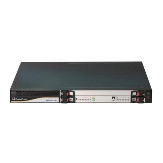
2: I V7122 HAPTER NSTALLING THE ATEWAY Figure 1 shows the front view of the V7122 media gateway. For information about the V7122 gateway LEDs, see Monitoring the V7122 LEDs. VT122 Gateway Front View Figure 1 V7122 Gateway Front View Component Descriptions... -
Page 12: Unpacking
Cable the V7122 gateway (see Cabling the V7122 Gateway). After powering-up the V7122 gateway, the Ready and LAN LEDs on the front panel turn to green (after a self-testing period of about three minutes). Any malfunction changes the Ready LED to red (see Monitoring the LEDs for details on the V7122 LEDs). -
Page 13: Mounting The V7122 Gateway
19-inch Rack & Desktop Accessories Figure 2 Mounting the V7122 Gateway The V7122 gateway can be mounted on a desktop, or installed in a standard 19-inch rack. Cabling the V7122 Gateway for cabling the V7122 gateway. Mounting the V7122 Gateway on a Desktop No brackets are required. - Page 14 Align a bracket over two holes on one side (so that the brackets larger holes face front) and with the two supplied replacement screws, screw in the bracket. Perform the same procedure on the other side. V7122 Gateway Front View with 19-inch Rack Mount Brackets Figure 3 CAUTION: Rack Mount Safety Instructions (UL)
-
Page 15: Cabling The V7122 Gateway
Cabling the V7122 Gateway The V7122 gateway is available in many configurations, that is, AC or DC, and 16-trunk, 8- trunk, 4-trunk, 2-trunk, or 1-trunk device. The 16-trunk dual AC... - Page 16 V7122 Gateway Rear Panel Cabling (16 Trunks, Dual AC Power) Component Table 3 Descriptions Item # Label Component Description RTM locking screws. Two Category 5 network cables, connected to the two Ethernet RJ- ETHERNET 45 ports. TRUNKS Two 50-pin Telco connector cables, each supporting eight trunks.
-
Page 17: Connecting The E1/T1 Trunk Interfaces
Connecting the Power Supply). Connecting the E1/T1 Trunk Interfaces Connect the V7122 gateway E1/T1 Trunk interfaces using either Telco or RJ-48 connectors: To connect E1/T1 trunk interface using 50-pin Telco connectors (16-trunk device), follow these 3 steps: Attach the Trunk cable with a 50-pin male Telco connector to the 50-pin female Telco connector labeled Trunks 1 8 on the Rear Transition Module (RTM). -
Page 18: Installing The Ethernet Connection
Connect the other end of the Category 5 network cables to your IP network. The Ethernet connectors (labeled Ethernet 1 and Ethernet 2) are wired according to Figure When you assign an IP address to the V7122 gateway using HTTP (under Step 1 in Section Assigning an IP Address Using HTTP), you may be required to disconnect this cable and re- cable it differently. -
Page 19: Connecting The Power Supply
For redundant operation it is recommended to connect each of the Ethernet connectors to a different switch. Connecting the Power Supply Connect the V7122 gateway to the power supply using one of the following methods: Connecting the AC Power Supply To connect power when using a single AC power cable: Attach one end of the supplied 100/240 VAC power cable to the rear AC socket and connect the other end to the correct earthed AC power supply. - Page 20 Each of the dual power cables can be connected to different power phases. Connecting the DC Power Supply To connect the V7122 gateway to a DC power supply use one of these two options: DC Terminal block with a screw connection type.
- Page 21 To connect DC power using a DC terminal block crimp connector, follow these 3 steps: Remove the DC adaptor (screw connection type) that is attached to the V7122 gateway rear panel. Connect the two insulated wires to the correct DC power supply. Ensure that the connections to the DC power supply maintain the correct polarity (see Figure 10).
- Page 22 V7122 Digital Gateway Installation Guide...
-
Page 23: Chapter 3: Configuring The V7122 Gateway
IP addresses to the V7122. Section Configuring the V7122 Basic Control Protocol Parameters describes how to set up the V7122 gateway with basic parameters using a standard Web browser (such as Microsoft Internet Explorer). Section Assigning the V7122 Gateway IP Address applies equally to H.323 and... -
Page 24: Assigning An Ip Address Using Http
If your network does not feature a default gateway, enter a dummy value in the Default Gateway IP Address field. Click the Reset button, and then at the prompt click OK; the V7122 gateway applies the changes and restarts. This takes approximately three minutes to complete. When the V7122 gateway completes the reset, the Ready and LAN LEDs on the front panel are lit green. -
Page 25: Assigning An Ip Address Using Bootp
BootP procedure can also be performed using any standard compatible BootP server. You can also use BootP to load the auxiliary files to the V7122 gateway (see the V7122 Digital Gateway User Guide). To assign an IP address using BootP, follow these 13 steps: Open the BootP application (supplied with the V7122 gateway software package). -
Page 26: Assigning An Ip Address Using The Cli
Maintenance Actions screen is displayed. From the Burn to FLASH drop-down list, select Yes and then click the Reset button; the V7122 gateway is shut down and re-activated. A message about the waiting period is displayed. The screen is refreshed. -
Page 27: Restoring Networking Parameters To Their Initial State
6) and to reset the username and password. Note that the V7122 gateway returns to the software version burned in flash. This process also restores the V7122 gateway parameters to their factory settings. Therefore, you must load your previously backed-up ini file, or the default ini file (received with the software kit) to set them to their correct values. -
Page 28: Accessing The Embedded Web Server
Configuring Basic SIP Parameters When you have completed the above relevant section you are then ready to start using the V7122 gateway. For information on how to fully configure the VoIP gateway, see the V7122 Digital Gateway User Guide. V7122 Digital Gateway Installation Guide... -
Page 29: Configuring Basic H.323 Parameters
Figure 13 To configure basic H.323 parameters, follow these 8 steps: If the V7122 gateway is connected to a router with NAT enabled, perform the following procedure. If it is not, leave the NAT IP Address field undefined. Determine the “public” IP address assigned to the router (by using, for instance, router Web management). - Page 30 Click Submit; the Trunk Group Table is automatically updated. Click Quick Setup; you are returned to the Quick Setup screen. Click the Reset button, and then at the prompt click OK; the V7122 gateway applies the changes and restarts. This takes approximately three minutes to complete. When the V7122 gateway has finished restarting, the Ready and LAN LEDs on the front panel are lit green.
-
Page 31: Configuring Basic Sip Parameters
Figure 14 To configure basic SIP parameters, follow these 11 steps: If the V7122 gateway is connected to a router with NAT enabled, perform the following procedure. If it is not, leave the NAT IP Address field undefined. Determine the “public” IP address assigned to the router (by using, for instance, router Web management). - Page 32 Under SIP Parameters, enter the V7122 gateway domain name in the Gateway Name field. If the field is not specified, the V7122 gateway IP address is used instead (default). When working with a Proxy server, set the Working with Proxy field to Yes, and then enter the IP address of the primary Proxy server in the Proxy IP Address field.
-
Page 33: Configuring The Trunk Settings
V7122 gateway completes the restart, Ready and LAN LEDs on the front panel are lit green. 10 After the gateway is reset, configure the V7122 gateway trunk parameters. For information about configuring the trunk parameters, see Configuring the Trunk Settings. - Page 34 If the trunk cant be stopped because it provides the gateways clock (assuming the V7122 gateway is synchronized with the E1/T1 clock), assign a different E1/T1 trunk to provide the gateways clock or enable TDM Bus PSTN Auto Clock on the TDM Bus Settings screen.
- Page 35 User Side when the PSTN or PBX side is configured as Network side, and vice-versa. If you do not know the V7122 gateway ISDN termination side, choose User Side and then open the Channel Status screen (by clicking the Home button). If the D- channel alarm is indicated, choose Network Side.
- Page 36 V7122 Digital Gateway Installation Guide...
-
Page 37: Chapter 4: Changing The
To prevent unauthorized access to the Embedded Web Server, two user accounts are available, a primary and secondary. For detailed information on the user account mechanism, see the V7122 Digital Gateway User Guide. It is recommended that you change the default username and password of the account after first accessing the Embedded Web Server. - Page 38 Click Change Password; the new password is applied immediately and the Enter Network Password screen appears (see Figure 12). Enter the updated password in the Enter Network Password screen. Note that the password can be a maximum of 19 case- sensitive characters. V7122 Digital Gateway Installation Guide...
-
Page 39: Chapter 5: Restoring And Configuration
To back up the ini file, follow these 4 steps: Click Get ini File; the File Download window opens. Click Save; the Save As window opens. Navigate to the folder where you want to save the ini file. V7122 Digital Gateway Installation Guide... - Page 40 Select the file and then click Open; the name and path of the file appear in the field beside the Browse button. Click Send ini File, and then at the prompt click OK; the gateway is automatically reset (from the cmp version stored on the flash memory). V7122 Digital Gateway Installation Guide...
-
Page 41: Monitoring The V7122 Gateway Leds
V7122 HAPTER ONITORING THE ATEWAY The V7122 gateway provides several ways for monitoring the status of the gateway: Monitoring the V7122 gateway LEDs (see Monitoring the V7122 LEDs). Monitoring the V7122 gateway trunks and B-channels using the Embedded Web Server... - Page 42 Power is supplied to the board The cPCI board can now be removed. SWAP READY Blue The cPCI board was inserted successfully. During correct V7122 operation, the ACT LED is lit green and the FAIL LED is off. V7122 Digital Gateway Installation Guide...
-
Page 43: Monitoring The V7122 Gateway Trunks And B-Channels
Monitoring the V7122 Gateway Trunks and B-channels To monitor the status of the trunks and B-channels: Open the Trunk & Channel Status screen by clicking the Home icon ; the Trunk & Channel Status screen is displayed. Trunk & Channel Status Screen... - Page 44 V7122 Digital Gateway Installation Guide...
-
Page 45: Chapter 7: Upgrading The Software Upgrade Wizard
Load Auxiliary Files (see Updating the Auxiliary Files). When upgrading the V7122 gateway software you must load the new cmp file with all other related configuration files. Software Upgrade Wizard The Software Upgrade Wizard guides you through the process of software upgrade -- selecting files and then loading them to the gateway. - Page 46 Software Upgrade button, the process must be followed through and completed with a V7122 gateway reset at the end. If you click the Cancel button in any of the subsequent screens, the V7122 gateway is automatically reset with the configuration that was previously burned in flash memory.
- Page 47 Click Browse, navigate to the cmp file and click the button Send File; the cmp file is loaded to the V7122 gateway and you are notified as to a successful loading. cmp File Successfully Loaded into the V7122 Gateway Notification...
- Page 48 Note that these are NOT the files you loaded in the previous Wizard steps. Click Reset; the V7122 gateway resets, utilizing the new cmp and ini file you loaded up to now as well as utilizing the other configuration files.
- Page 49 Figure 23 Follow the same procedure you followed when loading the ini file (see Step 6). The same procedure applies to the Load a VP file (not applicable to the V7122 gateway) screen and Load a coefficient file screen. In the FINISH screen (see Figure 24) , the Next button is disabled.
- Page 50 End Process Screen Figure 25 Click End Process; the Quick Setup screen appears and the full Web application is reactivated. V7122 Digital Gateway Installation Guide...
-
Page 51: Updating The Auxiliary Files
CAS, Voice Prompts, and Call Progress Tones (CPT). For information about additional auxiliary files, see the V7122 Digital Gateway User Guide. ini and Auxiliary Files Descriptions... - Page 52 Under the RESET group, select the Yes option from the Burn to FLASH drop-down list, and then click Reset; the auxiliary files are saved into flash and the V7122 gateway restarts. This takes approximately three minutes to complete. When the V7122 gateway has finished restarting, the Ready and LAN LEDs on the front panel are lit green.
-
Page 53: Chapter 8: Regulatory
Location I. Zusmanovich, Compliance Engineering Manager Czech [3Com Ltd] tímto prohlašuje, že tento [2000 Series] je ve shodě se základními požadavky a dalšími příslušnými ustanoveními směrnice 1999/5/ES." Danish Undertegnede [3Com Ltd] erklærer herved, at følgende udstyr [2000 Series] overholder de væsentlige krav og øvrige relevante krav i direktiv 1999/5/EF... -
Page 54: Safety Notices
Šiuo [3Com Ltd] deklaruoja, kad šis [2000 Series] atitinka esminius reikalavimus ir kitas 1999/5/EB Direktyvos nuostatas. Spanish Por medio de la presente [3Com Ltd] declara que el [2000 Series] cumple con los requisitos esenciales y cualesquiera otras disposiciones aplicables o exigibles de la Directiva 1999/5/CE Swedish Härmed intygar [3Com Ltd] att denna [2000 Series] står I överensstämmelse med de... -
Page 55: Industry Canada Notice
The products are for access to ISDN at 2048 kb/s and for access to G.703 Leased lines at 2048 kb/s. Network Compatibility The products support the Telecom networks in EU that comply with TBR4 and TBR13. V7122 Digital Gateway Installation Guide... -
Page 56: Telecommunication Safety
Increase the separation between the equipment and receiver. Connect the equipment into an outlet on a circuit different from that to which the receiver is connected. Consult the dealer or an experienced radio/TV technician for help. V7122 Digital Gateway Installation Guide... -
Page 57: Customer Support
UPPORT FOR RODUCT Customer Support Customer technical support and service are provided by 3Com Distributors, Partners, and Resellers from whom the product was purchased. For Customer support for products purchased directly from 3Com, contact support@3Com.com. V7122 Digital Gateway Installation Guide...