Furuno FA-150 Operator's Manual
Furuno uais transponder operator'smanual fa-150
Hide thumbs
Also See for FA-150:
- Installation manual (216 pages) ,
- Operator's manual (128 pages) ,
- Isntallation manual (57 pages)
Table of Contents
Advertisement
C
9-52 Ashihara-cho,
Nishinomiya 662-8580, JAPAN
Telephone : +81-(0)798-65-2111
Fax :
+81-(0)798-65-4200
All rights reserved.
Printed in Japan
Pub. No. OME-44310
( DAMI ) FA-150
(Elemental Chlorine Free)
The paper used in this manual
is elemental chlorine free.
Your Local Agent/Dealer
FIRST EDITION A2 : DEC. 14, 2004
D
: FEB. 10, 2006
UAIS Transponder
FA-150
http://www.furuno.co.jp/
Back
Advertisement
Table of Contents
Troubleshooting

Related Manuals for Furuno FA-150


Summary of Contents for Furuno FA-150
- Page 1 Fax : +81-(0)798-65-4200 FIRST EDITION A2 : DEC. 14, 2004 All rights reserved. Printed in Japan Pub. No. OME-44310 ( DAMI ) FA-150 (Elemental Chlorine Free) The paper used in this manual is elemental chlorine free. : FEB. 10, 2006 Back...
- Page 2 Continued use of the equipment can cause fire or electrical shock. Contact a FURUNO agent for service. Do not disassemble or modify the equipment. Fire, electrical shock or serious injury can result.
-
Page 3: Table Of Contents
TABLE OF CONTENTS FOREWORD ... iii SYSTEM CONFIGURATION...v PROGRAM NUMBER ...vi SYSTEM OVERVIEW ...vii 1. OPERATION... 1-1 1.1 Description of Controls ...1-1 1.2 Turning the Power On and Off...1-2 1.3 Adjusting Panel Dimmer and Contrast1-4 1.4 Menu Overview...1-5 1.4.1 Menu operating procedure ...1-5 1.5 Setting Up for a Voyage ...1-7 1.6 Setting CPA/TCPA... -
Page 4: Foreword
IEC 61993-2 (Type testing standard), IEC 60945 (EMC and environmental conditions). The FA-150 consists of VHF and GPS antennas, a transponder unit, a monitor unit, and several associated units. The transponder contains a VHF transmitter, two TDMA receivers on two parallel VHF channels, a DSC channel 70 receiver, interface, communication processor, and internal GPS receiver. - Page 5 • This manual is intended for use by native speakers of English. • FURUNO will assume no responsibility for the damage caused by improper use or modification of the equipment or claims of loss of profit by a third party.
-
Page 6: System Configuration
PR-240-CE Protected from the weather MONITOR UNIT FA-1502 (two units may be connected) UNIVERSAL AIS MENU DISP STATUS FA-150 12-24 VDC : Standard : Option : Local supply Exposed to the weather Exposed to the weather Protected from the weather Protected from the weather... -
Page 7: Program Number
PROGRAM NUMBER Location Monitor Unit (24P0062) MAIN Transponder Unit (24P0035) GPS Receiver **: Minor Modification Program No. Version No. 2450021 (Prog) 01.** 2450020 (Boot) 01.** 2450018 01.** 485026 40** Date of Modification... -
Page 8: System Overview
SYSTEM OVERVIEW System overview The Automatic Identification System (AIS) was originally developed to aid the Vessel Traffic Services (VTS) by use of a VHF transponder working on Digital Selective Call (DSC) at VHF CH70, and is still in use along the UK coastal areas and others. Some time later the IMO developed a Universal AIS using the new sophisticated technology called Self-Organized Time Division Multiple Access (SOTDMA) based on a VHF Data Link (VDL). - Page 9 Not all ships carry AIS The Officer of the Watch (OOW) should always be aware that other ships, and in particular leisure craft, fishing boats and warships, and some coastal shore stations (including Vessel Traffic Service centers) might not be fitted with AIS. The OOW should also be aware that AIS fitted on other ships as a mandatory carriage requirement might be switched off by the master if its use might compromise the security of the vessel.
-
Page 10: Operation
Shifts cursor; chooses menu items and options; enters alphanumeric data. Opens the menu. Terminates keyboard input; changes screen. Chooses a display screen; closes menu Adjusts panel dimmer and LCD contrast. Turns the power on and off. FA-150 Monitor unit MENU DISP STATUS FA-150... -
Page 11: Turning The Power On And Off
Press the PWR key to turn the equipment on or off. When powered, the equipment sounds a beep for several seconds and then proceeds in the sequence shown below. FURUNO ELECTRIC CORP. [STARTUP TEST] PROGRAM No.: BACKUP DATA : OK **.**: Program Version No. - Page 12 The FA-150 should be powered while underway or at anchor. The master may switch off the AIS if he believes that the continual operation of the AIS might compromise the safety or security of his ship. The AIS should be restarted once the source of danger has disappeared.
-
Page 13: Adjusting Panel Dimmer And Contrast1-4
1. OPERATION Adjusting Panel Dimmer and Contrast The panel dimmer and display contrast may be adjusted as follows: 1. Press the DIM key to show the dialog box below. 2. Use ▲ or ▼ to adjust panel dimmer; ◄ or ► to adjust contrast. 3. -
Page 14: Menu Overview
Menu Overview You can choose the functionality of the equipment through the menu. If you get lost in operation, press the MENU key until you return to the main menu. The complete menu tree is provided in the Appendix. 1.4.1 Menu operating procedure 1. - Page 15 1. OPERATION 5. Depending on the sub-menu selected, you will choose an option or enter alphanumeric data. Choosing an option The example below shows how to choose an option from the USER SETTINGS menu. (See the illustration on the previous page.) a) Use ▲...
-
Page 16: Setting Up For A Voyage
Setting Up for a Voyage There are seven items on the NAV STATUS menu that you will need to enter at the start of a voyage: navigation status, destination, arrival date, arrival time, number of crew, vessel type and draught. 1. - Page 17 1. OPERATION 4. NEW is selected; press the ENT key. NAV STATUS menu, page 2 (destination entry screen) 5. Press the ENT key. Use the CursorPad to enter destination and then press the ENT key. You may use up to 20 alphanumeric characters, and you may enter 20 destinations.
- Page 18 6. Press ► to show page 3 of the NAV STATUS menu. [ARRIVAL TIME] DATE TIME: NAV STATUS menu, page 3 (date and time of arrival entry screen) 7. DATE is selected; press the ENT key. 8. Use the CursorPad to enter the date of arrival and then press the ENT key. 9.
- Page 19 1. OPERATION 10 FUTURE USE ALL SHIPS OF THIS TYPE 11 FUTURE USE CARRYING DG, HS, OR MP(A) 12 FUTURE USE CARRYING DG, HS, OR MP(B) 13 FUTURE USE CARRYING DG, HS, OR MP(C) 14 FUTURE USE CARRYING DG, HS, OR MP(D) 15 FUTURE USE FUTURE USE 16 FUTURE USE FUTURE USE 17 FUTURE USE FUTURE USE...
-
Page 20: Setting Cpa/Tcpa
Setting CPA/TCPA Set the CPA (Closest Point of Approach) and TCPA (Time to Closest Point of Approach) range for which you want to be alerted to AIS targets close to own ship. When a ship’s CPA and TCPA are lower than that set here, the buzzer sounds (if active) and the message COLLISION ALARM appears. -
Page 21: Choosing A Display
1. OPERATION Choosing a Display Use the DISP key to choose a display. Each time the key is pressed, the display changes in the sequence shown below. TARGET LIST (See para. 1.7.2. ) Switch between these displays with OWN STATIC OWN STATIC DATA 1 DATA 2... -
Page 22: Plotter Display
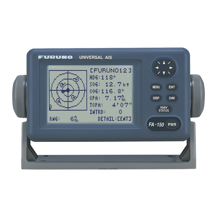
CPA and TCPA are lower than the CPA and TCPA alarm settings. Further, when a target becomes a lost target, “LOST” appears at the end of the HDG field. Selected target (circle filled in black) [FURUNO] Target name HDG: 111° Heading SOG: 10kt Speed COG: 111°... -
Page 23: Target List (Displaying Target Data)
1. OPERATION 1.7.2 Target list (displaying target data) 1. At the plotter display, press the DISP key to show the TARGET LIST, which lists all AIS targets being detected by the FA-150. Target's name, and range and bearing (from north) from own ship to target Note 1: If the dangerous target list appears, press ◄... - Page 24 Target data display, mobile class A [DETAILS SHIP] MMSI [A] : 431099806 MMSI no. NAME : FURUNO Name CALL SIGN : ZL6DEF1 Call sign IMO no. IMO No. : 109873421 : 0.02 nm TCPA : 0'17" TCPA [DETAILS SHIP] MMSI [A]: 431099806 MMSI No.
- Page 25 1. OPERATION Target data display, mobile class B [DETAILS SHIP] MMSI [B]: 431099806 NAME : FURUNO : 0.02 nm TCPA : 0'17" [DETAILS SHIP] MMSI [B]: 431099806 LAT : 34 ° 03.5442'N LON : 134 ° 30.3883'E S/C : 17.8 kt/ 213.5 °...
- Page 26 Target data display, base station "DNGR" (DANGER) appears (in reverse video) when a target's CPA and TCPA are lower than the CPA/TCPA setting. "LOST" appears (in reverse video) when signal from a target is lost. Six minutes and 40 seconds after loss of signal the target's data is erased.
- Page 27 1. OPERATION Target data display, AtoN (Aid to Navigation) [DETAILS AtoN] MMSI : 431099806 NAME : FURUNO CPA : 0.02 nm TCPA : 0'17" [DETAILS AtoN] MMSI : 431099806 LAT : 34 ° 03.5442'N LON : 134 ° 30.3883'E : 25.12 nm/351.5 °...
- Page 28 The table below shows all the AtoN codes which may appear on the AtoN target data display. The AtoN name which appears on the AtoN target display is shown in uppercase alphabet. A to N code and description Code DEFAULT, TYPE OF A TO N NOT SPECIFIED REFERENCE POINT RACON OFF SHORE STRUCTURE...
-
Page 29: Dangerous (Target) List
2. Use the CursorPad to view other own static data; ▼ or ► to go forward, ▲ or ◄ to go back. See the illustration on the next page for own ship’s static data examples. 1-20 [DANGEROUS LIST] NAME TCPA FURUNO 0.50 3'20" EXPLOR 1.20 3'35" INTREP 1.80 3'50"... - Page 30 [OWN STATIC DATA] 1/5 NAME : FURUNO VOYAGER CALL SIGN: CAL0001 MMSI : 123456789 IMO No. : 623498071 [OWN STATIC DATA] 2/5 DESTINATION: TOKYO DATE: 12/DEC TIME : 10:25 [OWN STATIC DATA] 3/5 DRAUGHT : 12.1 m NAV STATUS: 0...
-
Page 31: Own Dynamic Data Display
1. OPERATION 1.7.5 Own dynamic data display The OWN DYNAMIC DATA display shows your ship’s dynamic data, which includes time, date, ship’s position, course over ground (COG), speed over ground (SOG), rate of turn (ROT), and heading. The OOW should periodically check position, speed over ground and sensor information. -
Page 32: Messages
Messages You may send and receive messages via the VHF link, to a specified destination (MMSI) or all ships in the area. Messages can be sent to warn of safety of navigation; for example, an iceberg sighted. Routine messages are also permitted. - Page 33 1. OPERATION 5. ADRS TYPE is selected; press the ENT key. 6. Choose ADRS CAST to send a message to a specific AIS-equipped ship, or BROAD CAST to send a message to all AIS-equipped ships within broadcasting range. Press the ENT key. 7.
-
Page 34: Receiving Messages
The screen shows message status as follows: AIS message status messages and their meanings Message NOW SENDING. SEND MESSAGE COMPLETE. PRESS ANY KEY SEND MESSAGE UNSUCCESSFUL. PRESS ANY KEY SEND MESSAGE UNSUCCESSFUL. MMSI: XXXXXXXXX PRESS ANY KEY NOW WAITING RESPONSE. PRESS ANY KEY 1.8.2 Receiving messages... - Page 35 1. OPERATION 5. To view the contents of an unread message, use the CursorPad to choose the message and then press the ENT key. Below is an example of a received message. 6. Press the DISP key to close the log. Displaying received messages in a window You may display incoming messages in a window as follows: 1.
-
Page 36: Message Logs
1.8.3 Message logs The FA-150 stores the latest 20 each of transmitted and received messages in respective message logs. When a log becomes full, the oldest message in the log is automatically deleted to make room for the latest. To display a message log, do the following: 1. -
Page 37: Regional Operating Channels
1. OPERATION Regional Operating Channels AIS operates primarily on two dedicated VHF channels, CH 2087 and CH2088. Where these channels are not available regionally, the AIS is capable of being automatically switched to designated alternate channels by means of a message from a shore facility. -
Page 38: Displaying, Editing Regional Operating Area Status
1.9.2 Displaying, editing regional operating area status You may display the status of regional operating areas currently memorized in the equipment. Nine of any combination of AIS message from shore-based AIS, DSC message, manual settings and commands from ECDIS or a PC may be registered and one will be HIGH SEA. - Page 39 1. OPERATION 5. Press the ENT key to show details. 6. POWER is selected; press the ENT key to show the channel power options. 7. Use ▼ or ▲ to choose power desired and then press the ENT key. 8. CH NO. CH-A is selected; press the ENT key. 9.
- Page 40 19. LAT of RIGHT TOP is selected; press the ENT key. Use the CursorPad to enter latitude for the right-top position (northeast point) of the AIS operating area and then press the ENT key. 20. LON of RIGHT TOP is selected; press the ENT key. Use the CursorPad to enter longitude for the right-top position (northeast point) of the AIS operating area and then press the ENT key.
-
Page 41: Enabling/Disabling Buzzers, Key Beep
1. OPERATION 1.10 Enabling/Disabling Buzzers, Key Beep You may turn on or off the buzzers that sound for alarms or incoming messages. Further, you may turn off the beep which sounds for valid key input. Note that the alarm buzzer is not related to a radar or ECDIS alarm. 1. -
Page 42: Long Range Mode
LR MODE : AUTO AUTO SORT : ON CPA/TCPA ALARM USER SETTINGS sub-menu AUTO MANUAL [RECEIVED LR] MMSI: 431456789 NAME: FURUNO Press key RESPONSE? YES: [ENT] NO: OTHER 1. OPERATION [LR RESPONSE] MMSI: 431456789 NAME: FURUNO PRESS ANY KEY 1-33... - Page 43 Ship name, call sign, IMO number Date message created Position Course over ground Speed over ground Waypoint, ETA Draft Ship type, Load Ship length, width, type Number of crew 1-34 [LR RESPONSE] MMSI: 431456789 NAME: FURUNO PRESS ANY KEY Codes used in long range messages...
-
Page 44: Viewing Initial Settings
[ENT] key. VIEW LAN PORT* VIEW PRIORITY * Shown when optional LAN kit is installed. INITIAL SETTINGS menus 1. OPERATION : 999999999 : FURUNO : FQC3544 QUIT [MENU] A: 45m B: 15m QUIT[MENU] A: 45m B: 15m QUIT[MENU]... - Page 45 1. OPERATION This page intentionally left blank. 1-36...
-
Page 46: Maintenance, Troubleshooting
MAINTENANCE, TROUBLESHOOTING Maintenance Regular maintenance is necessary to maintain performance. A monthly maintenance program should be established and should at least include the items listed in the table below. Item Connectors Cabling Ground terminal Ground wire Monitor unit, Transponder unit WARNING ELECTRICAL SHOCK HAZARD Do not open the equipment. -
Page 47: Replacement Of Fuse, Resetting Breaker
2. MAINTENANCE, TROUBLESHOOTING Replacement of Fuse, Resetting Breaker 2.2.1 Replacement of fuse The power cable for the monitor unit contains a 3A fuse which protects the equipment from overvoltage, reverse polarity and equipment fault. If the power cannot be turned on, check if the fuse has blown. If it has blown, find the cause before replacing the fuse. -
Page 48: Troubleshooting
Troubleshooting The troubleshooting table below provides common symptoms of trouble and the means to rectify them. If you cannot restore normal operation, do not attempt to check inside the equipment. Refer any repair work to a qualified technician. Symptom Power Cannot turn on the power. -
Page 49: Diagnostics
2. MAINTENANCE, TROUBLESHOOTING Diagnostics The FA-150 provides diagnostic tests to check the monitor unit and transponder unit for proper operation. 2.4.1 Monitor unit test The monitor unit test shows program no., and checks the ROM, RAM, LCD and controls. 1. Press the MENU key to open the main menu. -
Page 50: Transponder Test
a) The first screen in the monitor test program sequence shows program no. b) After the program no. has been displayed, the message “PUSH KEY” appears, in reverse video. Press each key and arrows on the CursorPad one by one. The pressed key or arrow’s name appears next to “KEY” if the control is functioning normally. - Page 51 2. MAINTENANCE, TROUBLESHOOTING Internal GPS test The internal GPS receiver can be checked for proper operation as follows: 1. Press the MENU key to open the main menu. 2. Use the CursorPad to choose DIAGNOSTICS and then press the ENT key. 3.
-
Page 52: Power On/Off History
2.4.3 Power on/off history The PWR ON/OFF HISTORY log shows the date and time of the latest 30 power-ons and power-offs. If the interval between power-off and power-on is less than 15 minutes those times are not shown. 1. Press the MENU key to open the main menu. 2. -
Page 53: Alarm Status
2. MAINTENANCE, TROUBLESHOOTING Alarm Status The alarm status log shows the latest 25 dates and times alarms were violated. 1. At the plotter display, press the DISP key four times to show the ALARM STATUS display. 2. Use ▼ or ▲ to scroll the log. Alarm Status Indication CH70... -
Page 54: Error Messages
Error Messages The FA-150 displays the following error messages to alert you to invalid data, etc. Message CAN’T DISPLAY OVER LAT85° COLLISION ALARM COMMUNICATION ERROR ERROR REGIST GPS COMMUNICATION ERROR ILLEGAL MODE WAS SELECTED. PRESS ANY KEY. NO MESSAGE NO OWN SHIP POSITION... -
Page 55: Gps Monitor
2. MAINTENANCE, TROUBLESHOOTING Note: Detection of RX malfunction 1) Detection of TDMA RX malfunction Frequency error PLL chip on receiver board generates lock or unlock signal for synthesizer. MPU watches and sets status flag which reflects data of ALR sentence. ID 003 for RX1, ID 004 for RX2 2) Detection of DSC RX malfunction General error... -
Page 56: Displaying Sensor Status
Displaying Sensor Status The SENSOR STATUS screen shows sensor status. 1. Press the MENU key. 2. Use the CursorPad to choose SENSOR STATUS and then press the ENT key. Sensor status message 3. Press the DISP key to close the display. Sensor Status Message UTC CLOCK LOST EXTRL GNSS... -
Page 57: Restoring Default Settings
2. MAINTENANCE, TROUBLESHOOTING Restoring Default Settings You may clear all or specific settings to start afresh with default settings. When all data is cleared, the default settings for all items in the INIT SETTING and SYSTEM SETTINGS sub-menus are restored. GPS data is also cleared; however, MMSI and IMO numbers, ship’s name and call sign are not cleared. -
Page 58: Appendix
APPENDIX Menu Tree The example screens shown in this manual may not match the screens you see on your display. The screen you see depends on your system configuration and equipment settings. [MENU] key CREATE MSG SET MSG TYPE TX LOG SET MSG RX LOG SEND MSG... - Page 59 APPENDIX (Continued from previous page) CHANNEL VIEW CHANNEL (View power and channel settings of channel in use.) SETTINGS EDIT CHANNEL DIAG- MONITOR TEST (Displays program no.; checks ROM, RAM, LCD, controls.) NOSTICS TRANSPONDER TEST PWR ON/OFF HISTORY (Log for time of equipment power on and off.) TX ON/OFF HISTORY (Log for time of equipment transmission on and off.) MEMORY CLEAR FOR SERVICE (For service technician.
-
Page 60: Parts List
This equipment contains complex modules in which fault diagnosis and repair down to component level are not practical (IMO A.694(17)/8.3.1). Only some discrete components are used. FURUNO Electric Co., Ltd. believes identifying these components is of no value for shipboard maintenance; therefore, they are not listed in the manual. Major modules can be located on the parts location photo on page AP-4 and AP-5. -
Page 61: Parts Location
APPENDIX Parts Location Monitor unit CPU Board 24P0062 Transponder unit TX Board 24P0032 PWR Board 24P0037 Transponder unit, top cover removed AP-4 Monitor unit, rear cover opened MOT Board 24P0036... - Page 62 RX2 Board 24P0033 RX1 Board 24P0033 DSC Board 24P0033 Transponder unit, bottom cover removed APPENDIX GPS Receiver GN-8093 MAIN Board GPSTB Board 24P0035 24P0043 AP-5...
-
Page 63: Digital Interface (Iec 61162-1 Edition 2, Iec 61162-2
APPENDIX Digital Interface (IEC 61162-1 Edition 2, IEC 61162-2) Sentence data Input sentences ABM, ACA, ACK, AIR, BBM, DTM, GBS, GGA, GLL, GNS, HDT, LRF, LRI, OSD, RMC, ROT, SSD, VBW, VSD, VTG Output sentences ABK, ACA, ACS, ALR, LRF, LR1, LR2, LR3, TXT, VDM, VDO Transmission interval ABK: With each event ACA, ACS: At RX... - Page 64 Serial interface I/O circuit COM1, 2, 3 port Baud rate selectable from 4800 and 38400 (bps). LTC1535C COM 4, 5 port Baud rate selectable from 4800 and 38400 (bps). LTC1535C RD_2 2.2k. RD_1 COM6 port Baud rate selectable from 4800 and 38400 (bps). 2_ RD 2.2k 1_ RD/A D_ DATA...
- Page 65 APPENDIX DISP port Baud rate selectable from 4800 and 38400 (bps). LTC1535C Sentence description Input sentences ABM - Addressed binary and safety related message !--ABM,x,x,x,xxxxxxxxx,x,x.x,s--s,x*hh<CR><LF> | | | | | | | | | | | | +-------- 7 | | | | +------------ 6 | | | +--------------- 5...
- Page 66 ACA - AIS regional channel assignment message $--ACA,x,IIII.I, a,yyyyy.y,a,IIII.I,a,yyyyy.y,a,x,xxxx,x,xxxx,x,x,x,a,x,hhmmss.s*hh<CR><LF> 1. Sequence number, 0 to 9 2. Region Northeast corner latitude - N/S 3. Region Northeast corner longitude - E/W 4. Region Southwest corner latitude - N/S 5. Region Southwest corner longitude - E/W 6.
- Page 67 APPENDIX AIR - AIS interrogation request $--AIR,xxxxxxxxx,x.x,x,x.x,x,xxxxxxxxx,x.x,x*hh<CR><LF> +--------------- 6 | | +--------------------- 5 | +------------------------ 4 +--------------------------- 3 +------------------------------ 2 +------------------------------------- 1 1. MMSI of interrogated station 1 2. ITU-R M.1371 message requested from station 1 3. Message sub-section 4. Number of second message requested from station 1 5.
- Page 68 DTM - Datum reference $--DTM,ccc,a,x.x,a,x.x,a,x.x,ccc*hh<CR><LF> +------ 6 | +---------- 5 | +---+------------- 4 | +---+------------------- 3 | +------------------------- 2 +---------------------------- 1 1. Local datum W84 - WGS84 W72 - WGS72 S85 - SGS85 P90 - PE90 999 - User defined IHO datum code 2.
- Page 69 APPENDIX GGA - Global positioning system (GPS) fix data $--GGA,hhmmss.ss,llll.ll,a,yyyyy.yy,a,x,xx,x.x,x.x,M,x.x,M,x.x,xxxx*hh<CR><LF> +----+--------------------------------- 3 +---+--------------------------------------------- 2 +------------------------------------------------------------- 1 1. Not used 2. Latitude, N/S 3. Longitude, E/W 4. GPS quality indicator 5. Not used 6. Not used 7. Not used 8. Not used 9.
- Page 70 GNS - GNSS fixed data $--GNS,hhmmss.ss,llll.ll,a,yyyyy.yy,a,c--c,xx,x.x,x.x,x.x,x.x,x.x*hh<CR><LF> +-------+--------------------------------- 3 +--+--------------------------------------------- 2 +------------------------------------------------------------- 1 1. Not used 2. Latitude, N/S 3. Longitude, E/W 4. Mode indicator 5. Not used 6. Not used 7. Not used 8. Not used 9. Not used 10. Not used 11.
- Page 71 APPENDIX LRI - Long-range interrogation $--LRI,x,a,xxxxxxxxx,xxxxxxxxx,llll.ll,a,yyyyy.yy,a,llll.ll,a,yyyyy.yy,a*hh<CR><LF> +--+------------------------------------- 5 +--------------------------------------------------- 4 +------------------------------------------------------------- 3 | +------------------------------------------------------------------- 2 +--------------------------------------------------------------------- 1 1. Sequence number, 0 to 9 2. Control Flag 3. MMSI of requestor 4. MMSI of destination 5. Latitude - N/S(north-east coordinate) 6. Longitude - E/W(north-east coordinate) 7.
- Page 72 RMC - Recommended minimum specific GPS/TRANSIT data $--RMC,hhmmss.ss,A,llll.ll,a,yyyyy.yy,a,x.x,x.x,xxxxxx,x.x,a,a*hh<CR><LF> +---+---------------------------------------- 3 +--------------------------------------------------- 2 +---------------------------------------------------------- 1 1. UTC of position fix 2. Status: A=data valid, V=navigation receiver warning 3. Latitude, N/S 4. Longitude, E/W 5. Speed over ground, knots 6. Course over ground, degrees true 7.
- Page 73 APPENDIX SSD - UAIS ship static data $--SSD,c--c,c--c,xxx,xxx,xx,xx,c, aa*hh<CR><LF> | | | | | | | | +--- 8 | +----- 7 +------- 6 +---------- 5 +-------------- 4 +------------------ 3 +---------------------- 2 +--------------------------- 1 1. Ship's Call Sign, 1 to 7 characters 2.
- Page 74 VSD - UAIS voyage static data $--VSD,x.x,x.x,x.x,c--c,hhmmss.ss,xx,xx,x.x,x.x*hh<CR><LF> +----------------------- 5 +------------------------------ 4 +----------------------------------- 3 +--------------------------------------- 2 +------------------------------------------- 1 1. Type of ship and cargo category, 0 to 255 2. Maximum present static draught, 0 to 25.5 Meters 3. Persons on-board, 0 to 8191 4.
- Page 75 APPENDIX Output sentences ABK - UAIS addressed and binary broadcast acknowledgement $--ABK,xxxxxxxxx,a,x.x,x,x*hh<CR><LF> | | | | | | | +--- 6 | | +----- 5 | +------- 4 | +---------- 3 +------------- 2 +------------------- 1 1. MMSI of the addressed AIS unit 2.
- Page 76 LRF - See “Input sentences.” LR1 - Long-range reply with destination for function request “A” $--LR1,x,xxxxxxxxx,xxxxxxxxx,c--c,c--c,xxxxxxxxx*hh<CR><LF> +---------------------- 4 +------------------------------ 3 +---------------------------------------- 2 +---------------------------------------------- 1 1. Sequence Number 2. MMSI of responder 3. MMSI of requestor(reply destination) 4. Ship's name, 1 to 20 characters 5.
- Page 77 APPENDIX LR3 - Long-range reply for function requests “I, O, P, U and W” $--LR3,x,xxxxxxxxx,c--c,xxxxxx,hhmmss.ss,x.x,x.x,x.x,x.x,x.x,x.x*hh<CR><LF> +---------------------------------------- 4 +---------------------------------------------- 3 +------------------------------------------------------ 2 +------------------------------------------------------------ 1 1. Sequence Number 2. MMSI of responder 3. Voyage destination, 1 to 20 characters 4. ETA Date: ddmmyy 5.
- Page 78 VDM - VHF data-link message !--VDM,x,x,x,a,s--s,x*hh<CR><LF> | | | | | | | | | +--- 7 | | | | | +----- 6 | | | | +-------- 5 | | | +------------ 4 | | +-------------- 3 | +---------------- 2 +------------------ 1 1.
-
Page 79: Vhf Channel List
APPENDIX VHF Channel List International mode Ch No. FREQUENCY Ch No. 1001 156.05 1088 1002 156.1 1201 1003 156.15 1202 1004 156.2 1203 1005 156.25 1204 156.3 1205 1007 156.35 1206 1018 156.9 1207 1019 156.95 1020 1021 157.05 1022 157.1 1023 157.15... - Page 80 USA mode Ch No. FREQUENCY Ch No. 1001 156.05 1088 1201 1003 156.15 1202 1203 1005 156.25 1204 156.3 1205 1007 156.35 1206 1018 156.9 1207 1019 156.95 1020 1021 157.05 1022 157.1 1023 157.15 1024 157.2 1025 157.25 1026 157.3 1027 157.35...
- Page 81 APPENDIX This page intentionally left blank. AP-24...
-
Page 82: Specifications
VDM, VDO, ABK, ACA, ALR, TXT, LR1, LR2, LR3, LRF, LRI Note: COM4 also functions as SENSOR input. IEC 61162-1(2000-07)/61162-2(1998-09) DTM, GNS, GLL, GGA, RMC, VBW, VTG, OSD, HDT, GBS, ROT RS-232C (PC) RS-232C Contact closure AD-10 format (FURUNO gyro format) SP-1 FA-150 E4431S01C 060117... - Page 83 100-115/200-230 VAC, 1 phase, 50/60 Hz -25°C to +70°C -15°C to +55°C 95% at 40°C IPX6 IP20 IP22 From 2 Hz-5 Hz to 13.2 Hz: Amplitude ±1 mm ±10% (Maximum acceleration at 13.2Hz: 7m/s N9.5 2.5GY5/1.5 SP-2 FA-150 E4431S01C 060117...
-
Page 84: Index
INDEX Alarm status...2-8 Alarm status display ...1-22 Breaker reset ...2-2 Buzzer...1-32 Channels setting ...1-29 viewing...1-28 Contrast ...1-4 Controls ...1-1 CPA/TCPA ...1-11 Dangerous (target) list...1-20 Diagnostics GPS test (transponder) ...2-6 memory test...2-5 memory test (transponder) ...2-5 monitor unit test ...2-4 power on/off history ...2-7 Tx on/off history ...2-7 Digital interface...AP-6 DIM key...1-4...