Table of Contents
Advertisement
Quick Links
OPERATING INSTRUCTIONS FOR
Model 6750
Total Organic Carbon Analyzer
P/N M
ECO:
DANGER
Toxic gases and or flammable liquids may be present in this monitoring system.
Personal protective equipment may be required when servicing this instrument.
Hazardous voltages exist on certain components internally which may persist
for a time even after the power is turned off and disconnected.
Only authorized personnel should conduct maintenance and/or servicing.
Before conducting any maintenance or servicing, consult with authorized
supervisor/manager.
Teledyne Analytical Instruments
Advertisement
Table of Contents

Related Manuals for Teledyne 6750


Summary of Contents for Teledyne 6750
- Page 1 OPERATING INSTRUCTIONS FOR Model 6750 Total Organic Carbon Analyzer P/N M ECO: DANGER Toxic gases and or flammable liquids may be present in this monitoring system. Personal protective equipment may be required when servicing this instrument. Hazardous voltages exist on certain components internally which may persist for a time even after the power is turned off and disconnected.
- Page 2 Teledyne Instruments/ Analytical Instruments, 16830 Chestnut Street, City of Industry, CA 91749- 1580.
- Page 3 Total Organic Carbon Analyzer Specific Model Information Instrument Serial Number: _______________________ Instrument Range: _______________ Calibrated for: _______________ Background Gas: _______________ Zero Gas: _______________ Span Gas: _______________ Teledyne Analytical Instruments...
- Page 4 Model 6750 Safety Messages Your safety and the safety of others is very important. We have provided many important safety messages in this manual. Please read these messages carefully. A safety message alerts you to potential hazards that could hurt you or others.
- Page 5 Manuals do get lost. Additional manuals can be obtained from TI/AI at the address given in the Appendix. Some of our manuals are available in electronic form via the internet. Please visit our website at: www.teledyne-ai.com. Teledyne Analytical Instruments...
-
Page 6: Table Of Contents
Model 6750 Table of Contents List of Figures................ix List of Tables ................xi Introduction .................. 1 1.1 Main Features of the Analyzer 1.2 Options 1.3 Typical Applications 1.4 Intended Use of the Analyzer 1.5 Operator Interface Theory of Operation ..............5 2.1 Overview... - Page 7 5.3 Module Service 5.3.1 NDIR (Gas Calibration) 5.3.2 NDIR Service 5.3.3 Master Interface Board (P/N ST13042-1). 5.3.4 D. C. Power Supply 5.3.5 CE Computer (P/N 13039) 5.3.6 UV Lamp (P/N ST20009) 5.3.7 UV Reactor Assembly (P/N ST20003-1) Teledyne Analytical Instruments...
- Page 8 Model 6750 5.3.8 UV Power Supply 5.3.9 Mass Flow Controller (P/N ST18001A) 5.3.10 Metering Valve (P/N ST16050) 5.3.11 Sparger (P/N ST20025) 5.3.12 Pumps 5.3.12.1 Pump Motor Replacement 5.3.12.2 Pump Head Tubing Replacement 5.3.13 4-20 mA Adjustment Procedure 5.3.13.1 Setting 100 mV Control Voltage 5.3.13.2 Setting of 4-20 mA output...
-
Page 9: List Of Figures
Total Organic Carbon Analyzer List of Figures Figure 1-1: The Model 6750 TOC Analyzer (Front door removed) . 3 Figure 2-1: NPOC or TOC – Direct Method........6 Figure 2-2: TOC – True Method ............. 6 Figure: 2-3: TOC Measurement Basics .......... 8 Figure 2-4: UV/Persulfate Method .......... - Page 10 Model 6750 Figure 5-6: DC Power Supply Module........... 54 Figure 5-7: Replacing CE Computer ..........55 Figure 5-8: UV Lamp Replacement ..........56 Figure 5-9: Removing the UV Reactor Assembly......57 Figure 5-10: Removing the UV Power Supply....... 59 Figure 5-11: Mass Flow Controller ..........60 Figure 5-12: Metering Valve ............
-
Page 11: List Of Tables
Total Organic Carbon Analyzer List of Tables Table 4-1: Preparation of Standards (TOC/TIC) ......37 Table 5-1: Troubleshooting ............44 Teledyne Analytical Instruments... - Page 12 Since the use of this instrument is beyond the control of Teledyne Instruments/ Analytical Instruments, referred as TI/AI, no responsibility by TI/AI, its affiliates, and agents for damage or injury from misuse or neglect of this equipment is implied or assumed.
-
Page 13: Main Features Of The Analyzer
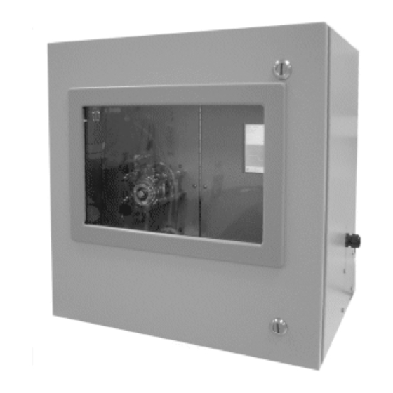
The Model 6750 TOC is shown in Figure 1-1. 1.1 Main Features of the Analyzer The Model 6750 TOC Analyzer is sophisticated, yet simple to use. The main features of the analyzer include: • TC (Total Carbon) analysis •... -
Page 14: Options
• Multi-Stream Analysis • DBPR Drinking Water 1.3 Typical Applications With excellent TOC accuracy from low parts-per-million to high concentration levels of salt-free samples, the Model 6750 is used in a variety of applications including: Boiler Feedwater Standard Method 5310 C/D Cooling Water EPA 415.1... -
Page 15: Operator Interface
1.5 Operator Interface The Model 6750 Analyzer is housed in a rugged metal case and may be wall or rack mounted for operator convenience. The enclosure is equipped with a viewing window on the front panel and all operator serviceable components may be viewed through the cabinet window, including the display. - Page 16 Introduction Model 6750 Teledyne Analytical Instruments...
-
Page 17: Theory Of Operation
The following discussion is intended to provide the user adequate information in order to allow intelligent cost/performance trade-offs and select the appropriate TOC method for each application. The Model 6750 TOC Analyzer performs the following analyses on the SAME sample: •... -
Page 18: Figure 2-1: Npoc Or Toc - Direct Method
Theory of Operation Model 6750 To perform correct TOC analysis, the analysis system must be capable of measuring all constituents of organic carbon present in the sample: Non-Purgeable Organic Carbon (NPOC) and Purgeable Organic Carbon (POC). Correct TOC analysis must also exclude the Total Inorganic Carbon (TIC) interference. - Page 19 TIC measurement and a simple mathematical difference to derive a “TOC” analysis. In the TOC-True method used by the Model 6750, the analyzer actually performs both TC and TIC measurements simultaneously and continuously on the same sample. The TOC Measurement Basics and Methods are illustrated in Figures 2-3 and 2-4.
-
Page 20: Figure: 2-3: Toc Measurement Basics
Theory of Operation Model 6750 Figure: 2-3: TOC Measurement Basics Figure 2-4: UV/Persulfate Method Teledyne Analytical Instruments... -
Page 21: The Uv/Heated Persulfate Method Of Analysis
Total Organic Carbon Analyzer Theory of Operation 2.3 The UV/Heated Persulfate Method of Analysis In the UV/Heated Persulfate Method as used by the Model 6750, the sample is initially mixed with acid and directed to the sparger. For TOC-Direct (NPOC) analysis, the CO... -
Page 22: Figure 2-5: Comparison Of Toc Measurement Technologies
Theory of Operation Model 6750 Figure 2-5: Comparison of TOC Measurement Technologies Teledyne Analytical Instruments... -
Page 23: Subsystems Principles Of Operation
Total Organic Carbon Analyzer Theory of Operation 2.4 Subsystems Principles of Operation The Model 6750 TOC Analyzer is comprised of five subsystems: 1. Sample Handling 2. Inorganic Carbon Removal – OR – Inorganic Carbon Analysis/TOC-True Method 3. Oxidation 4. NDIR CO Gas Detection 5. -
Page 24: Figure 2-6: Sample Handling For Toc -Direct
Theory of Operation Model 6750 actual measurement of the TIC, a more accurate TOC is achieved since (TOC = TC - TIC). “TOC-Direct” mode is preferred for accuracy when no or little volatiles are present. In this mode, the carbonate-free sample is extracted from the organic carbon reactor and measured directly as TOC. -
Page 25: Gas Phase Sample Handling
It is a pressure swing absorption PSA device requiring only electricity only to operate. Also available from Teledyne is an Instrument Air Purifier (P/N ST200019). This device can supply the oxygen demands of the instrument using facility instrument air. -
Page 26: Inorganic Carbon Removal/Analysis
The NPOC analysis ignores the volatile organics for a less precise NPOC analysis if organic volatiles are present. The sparger used in the Model 6750 is a gas/liquid counter-flow stripper. Actual acid addition depends on the amount of sample buffering and pH. -
Page 27: Oxidation
The UV reactor and persulfate reagent provide oxidation of the carbon to CO . The UV reactor consists of the following: • Mounting enclosure with viewing window • Borosilicate reactor body • Heater/Temperature sensor • UV Lamp • Miscellaneous fittings and clamps Teledyne Analytical Instruments... -
Page 28: Figure 2-9: Oxidation Reactions
Theory of Operation Model 6750 The construction of the patented UV reactor in the Model 6750 affords superior oxidation by precisely controlling the sample temperature, adding a precise amount of ultra-pure persulfate reagent (P/N ST40000) and precisely controlling the carrier gas flow rate. -
Page 29: Ndir Co Gas Detection
The key component for reliable TOC analysis is the precise and interference-free detection of CO . The Model 6750 NDIR unit requires very little maintenance because of its ability to handle the corrosive gases generated in TOC analysis. This is due in part to its non-reflective borosilicate sample cell. -
Page 30: Electronic Signal Processing, Display And Control
Theory of Operation Model 6750 requires no wall reflectivity and is completely resistant to corrosive gases. The NDIR unit requires no optical chopper motor or mechanical devices but utilizes a single flashing infrared source to optically “chop” the infrared (IR) beam, which equally irradiates CO /reference detectors. -
Page 31: Benchmark/Auto-Validation
LEANING On command (manual or automatic by selection of day/time), the combination of valves V3 and V4 operate to introduce a “cleaning” solution, depending on the chemical constituents of the sample. Acid or persulfate is generally used. Teledyne Analytical Instruments... - Page 32 Theory of Operation Model 6750 Teledyne Analytical Instruments...
-
Page 33: Unpacking The Analyzer
These drawings should be referred to when ordering spare parts, operating or servicing the equipment. See the Appendix for the AS BUILT drawing package. Installation of the Model 6750 On-line UV/Heated Persulfate TOC Analyzer includes: 1. Unpacking 2. -
Page 34: Figure 3-1: Analyzer Dimensions
Installation Model 6750 Figure 3-1: Analyzer Dimensions Figure 3-2: Required Door Clearance Teledyne Analytical Instruments... -
Page 35: Electrical Connections
Internal components of the Model 6750 TOC Analyzer are shown in Figure 3-3. Figure 3-3: Internal Components of the Model 6750 Analyzer 3.3 Electrical Connections... -
Page 36: Analog Outputs
There are two analog output signal connections. There are two wires per output with the polarity noted. See “As Built Drawings” in the Appendix. The outputs are non isolated 4-20 mA. Figure 3-4: Electrical Connections to the Model 6750 Teledyne Analytical Instruments... -
Page 37: Alarm Connections
3.4 Gas/liquid Connections Refer to the “As Built Drawings” in the Appendix for details and Figure 3-5. The Model 6750 Analyzer provides easy access for liquid, gas, vent and drain connections. 3.4.1 Liquid Connections Liquid phase sample connections include the following: (See Figure 3-5): •... -
Page 38: Gas Connections
Installation Model 6750 • Reagents • Drain (s) Connect these lines as per Figure 3-4 and the AS-BUILT drawings in the Appendix. Make sure there are no restrictions or kinks in the sample lines. Figure 3-5: Gas and Liquid Connections to the Analyzer 3.4.2 Gas Connections... -
Page 39: Checking The System
Prior to powering up the system and using the instrument for analysis, the system must be configured for your application and calibrated. This is described in Section 4. Teledyne Analytical Instruments... - Page 40 Installation Model 6750 Teledyne Analytical Instruments...
-
Page 41: Setup And Operation
(jar, pipe, etc.). AN AIR GAP AS DEFINED IS MANDATORY. CAUTION: FAILURE TO OBSERVE THIS WILL RESULT IN IMPROPER OPERATION. 3. ELECTRICAL – Assure proper electrical installation. Refer to facility requirements. 4. SAFETY – All customer and Teledyne specified safety measures are followed. Teledyne Analytical Instruments... -
Page 42: Figure4-1: Drain Connections
Setup and Operation Model 6750 Figure4-1: Drain Connections 5. On initial start–up or after UV Reactor or Glass Liquid Separator (GLS) servicing, fill the U-Tube with D. I. water as indicated in Figure 4-2. 6. After all of the above checks, turn analyzer ON by activating the facility power switch. -
Page 43: Menus
Then the analyzer may be placed in service. 4.2 Menus The advanced design of the Model 6750 TOC Analyzer eliminates complicated, routine, and sometimes confusing menus. The operator/software interface is simple and easy to use. Menus prompt the user for required actions or input. -
Page 44: Parameter Menu
Setup and Operation Model 6750 • The current TOC value, [IR] IR response • • [Flow] Carrier Gas Flow rate • [m] Available Memory (kb). 4.2.2 Parameter Menu Although your analyzer has been optimally configured for your application, on initial startup the setup parameters should be verified Consult Factory Settings for Your Application –... -
Page 45: Alarm Settings
(not the value of the Liquid Span). 4.2.3 Alarm Settings The next settings to verify or set are the Alarm Settings. To adjust the alarm settings: From the [Edit] Menu, select [Alarms]. The following Menu appears: Teledyne Analytical Instruments... -
Page 46: Stream Sequencer
Setup and Operation Model 6750 From this menu verify or change the concentration alarm setpoints using the onscreen scroll arrows. 4.2.4 Stream Sequencer If your analyzer has been configured for a multi-stream sequencer (P/N ST200009), from the [Edit] Menu, select [Sequencer]. The... -
Page 47: D/Dbpr
This optional utility allows convenient external pH calibration and input of alkalinity data consistent with the D/DBPR requirements If your analyzer has been configured for the D/DBPR option, from the following [Edit] Menu, select [D/DBPR]. The following screen appears: Teledyne Analytical Instruments... -
Page 48: Detailed Calibration Procedures
Setup and Operation Model 6750 The following window is illustrative of the D/DBPR [Run] screen. 4.3 Detailed Calibration Procedures 1. Although the instrument has been calibrated to your specifications at the factory, it should be rechecked after satisfactory installation and periodically calibrated as suggested for your application. - Page 49 .475 gm/L H Add amounts shown (in milliliters or grams) to clean dry, one liter volumetric flask and dilute to one (1) liter with distilled, deionized water. 4. Reagent Preparation: PREPARATION OF ONE MOLAR SODIUM PERSULFATE SOLUTION (OXIDIZING REAGENT) Teledyne Analytical Instruments...
- Page 50 It should be noted that some reagent grade sodium persulfate is not really “pure”. All persulfate supplied by Teledyne is guaranteed to have sufficient purity for proper operation. 5. Acid Preparation: Phosphoric Acid is the acid of choice.
- Page 51 (approximately 15 minutes). e. Select [SPAN]. It is recommended that the operator continue to observe the reading and if not stabilized at the desired span setting ± 2%, repeat the span selection until stable. Teledyne Analytical Instruments...
-
Page 52: Operation
Setup and Operation Model 6750 f. If the calibration is acceptable, select [OK] or [CANCEL] if not acceptable. The analyzer is now calibrated and ready for analysis. 4.4 Operation After proper installation and calibration, the instrument is ready to be placed “ON-LINE” for continuous operation. -
Page 53: Shutdown
Previous data may be obtained by selecting [CHART] from the screen. The following menu will appear. The display scale can be adjusted using the Select [TOC SCALE] item from the [CHART] menu. The following screen will appear. Edit Scale as desired. Teledyne Analytical Instruments... - Page 54 Setup and Operation Model 6750 To view the data produced in the last 24 hours, select [LAST 24 HOURS]. The following screen will appear: Using the Scroll Bar, select the data to be viewed. Selecting [HISTORICAL DATA] allows you to view any archived data within the memory limits of the computer.
-
Page 55: Maintenance
5.1 Compupter-aided Testing Prior to performing detailed troubleshooting procedures listed below, first perform computer-aided testing of the analyzer, as follows: 1. From the screen, select [TEST]. The following menu appears: 2. Select [SYSTEM DIAGNOSTICS]. The following menu appears: Teledyne Analytical Instruments... -
Page 56: Troubleshooting
Maintenance Model 6750 From this screen the operator may perform individual testing of components related to functionality and settings. 5.2 Troubleshooting If you are experiencing trouble with your instrument, refer to Table 5-1: Troubleshooting. Table 5-1: Troubleshooting PROBLEMS SOLUTION Check fuse & power connections. -
Page 57: Module Service
2. Select [INFRARED ANALYZER]. The following Screen will appear: 3. Disconnect tubing from reactor output and connect IR calibration adapter (P/N ST20026) as shown in Figures 5- 1, 5-2, and 5-3. 4. Connect facility tubing to “Zero” and “Span” Gas Bottles Teledyne Analytical Instruments... -
Page 58: Figure 5-1: Disconnecting Tubing From Reactor
Maintenance Model 6750 Figure 5-1: Disconnecting Tubing from Reactor Figure 5-2: IR Calibration Adapter P/N ST20026 Teledyne Analytical Instruments IR Calibration... -
Page 59: Ndir Service
The NDIR unit has now been properly calibrated. Reconnect the fitting to reactor output tube. 5.3.2 NDIR Service To remove and service the NDIR, simply follow the illustrated sequence as described in this section following Figure 5-4. Teledyne Analytical Instruments... -
Page 60: Figure 5-4: Removing The Ndir Unit P/N St36000
Maintenance Model 6750 Figure 5-4: Removing the NDIR Unit P/N ST36000 To Replace the NDIR Unit: 1. Turn off power. 2. Remove inlet tube from NDIR Assembly. 3. Remove vent tube from NDIR Assembly. 4. Unplug interface cable from NDIR Assembly. - Page 61 Total Organic Carbon Analyzer Maintenance Remove insulation from IR • Cell. Remove lock-tight from three • thumbnuts and remove. Slide out and remove Source • Assembly. Teledyne Analytical Instruments...
- Page 62 Maintenance Model 6750 Remove IR Cell Assembly • Note: a. ‘O’-Rings in each of Detector Assembly (left) and Source Assembly (right). b. Sapphire windows located under ‘O’-Rings Teledyne Analytical Instruments...
- Page 63 *Recommend using toothpick. Clean sapphire windows with a • soft, lintless tissue (use DI water, if necessary). To Reassemble Install IR Cell. • Install Source Assembly end • piece. Note: Large outlet port goes into Detector Assembly (left) Teledyne Analytical Instruments...
- Page 64 Maintenance Model 6750 Tighten three thumbnuts until • Source Assembly bottoms out on squeeze nuts. • Recommend: Use alternate tightening sequence Note: IR Cell installed incorrectly. Large outlet port MUST go into Detector Assembly (left) Insert lock-tight on three thumbnuts to prevent backoff.
-
Page 65: Master Interface Board (P/N St13042-1)
Figure 5-5: Removing the Master Interface Board To Remove the PC Board: 1. Turn off power. 2. Remove plastic cover. 3. Disconnect connectors. 4. Remove panel. Note: Depending on the configuration, there may be one or two master interface boards. Teledyne Analytical Instruments... -
Page 66: Power Supply
Maintenance Model 6750 5.3.4 D. C. Power Supply The power supply has no field adjustment. If malfunctioning, replace the module (P/N ST15083) using the directions below. See Figure 5-6. Figure 5-6: DC Power Supply Module To replace the module: 1. Turn off power. -
Page 67: Ce Computer (P/N 13039)
4. Remove module. 5. Install new CE Computer in reverse disassembly instruction procedure steps. (Install electrical connectors per supplied drawing). 6. Verify proper software install per directions shipped with new CE Computer. 7. Recalibrate liquid zero and span values. Teledyne Analytical Instruments... -
Page 68: Uv Lamp (P/N St20009)
Maintenance Model 6750 5.3.6 UV Lamp (P/N ST20009) Normal lamp replacement frequency is suggested at least every 12 months, however, if a lamp is “burned-out” (weak or no blue glow), replace with UV Lamp (P/N ST20009), per directions in Figure 8. -
Page 69: Uv Reactor Assembly (P/N St20003-1)
(P/N ST20003-1). See Figure 5-9. Figure 5-9: Removing the UV Reactor Assembly To Replace the UV Reactor Assembly: 1. Turn off UV Lamp at the UV Power Supply. Remove Persulfate and Acid Reagent lines from containers, as Teledyne Analytical Instruments... -
Page 70: Uv Power Supply
Maintenance Model 6750 well as the sample inlet line and submerse all three (3) lines into D. I. water to completely flush system. CAUTION: FAILURE TO DO SO MAY RESULT IN ACID BURNS, CLOGGED REACTOR, ETC. FLUSH FOR 30 MINUTES. -
Page 71: Mass Flow Controller (P/N St18001A)
1. Shut off Power to Instruments. 2. Shut off all gas to analyzer and bleed system for “O” pressure. 3. Disconnect fittings/tubing. 4. Loosen screws holding Module in-place. 5. Remove Module 6. Recalibrate analyzer after re-installation of exchange Module. Teledyne Analytical Instruments... -
Page 72: Metering Valve (P/N St16050)
Maintenance Model 6750 Figure 5-11: Mass Flow Controller 5.3.10 Metering Valve (P/N ST16050) If no O /air flow to the sparger (P/N ST20025) is observed (no bubbles), check for tubing and fitting leaks, restrictions and adjust metering valve (be careful to return to previous indicated bubble rate). -
Page 73: Sparger (P/N St20025)
SEVERE BURNS AND CAUSE LUNG AND RESPIRATORY DAMAGE. WEAR PROPER PROTECTIVE CLOTHING AND SAFETY GLASSES WITH SPLASH SHIELDS. TREAT ALL ACIDS WITH CAUTION AND HANDLE WITH CARE. ALWAYS WORK IN AN APPROVED FUME HOOD WHEN HANDLING OPEN CONTAINERS OF ACIDS. Teledyne Analytical Instruments... -
Page 74: Figure 5-13: Sparger
Maintenance Model 6750 1. Turn machine OFF. 2. Turn carrier gas (Air/O ) OFF. 3. Remove and drain tubing and sparger. 4. Remove sparger from spring clips. To clean the sparger: 1. Run warm water through tubing to flush out any solid contamination. -
Page 75: Pumps
Section 5.3.12.2 and Figure 5-15. 5.3.12.1 P OTOR EPLACEMENT Note: Masterflex pump heads must be removed for access to Pump Motor Mounting Screws. 1. Turn main power OFF. 2. Remove 4 wing nuts from pump head mounting hardware. Teledyne Analytical Instruments... - Page 76 Maintenance Model 6750 3. Remove pump as illustrated to gain access to pump mounting screws. 4. Remove two thumbscrews for pump panel removal. 5. Disconnect Pump Motor Connector. Teledyne Analytical Instruments...
-
Page 77: Pump Head Tubing Replacement
Note: Actual mounting panel may appear somewhat different but mounting hardware is the same. 5.3.12.2 P UBING EPLACEMENT 1. Separate the end bells (the pump head halves). 2. Hold the end bell containing the rotor as shown with the tubing retainer grooves pointing down. Teledyne Analytical Instruments... - Page 78 Maintenance Model 6750 3. Place tubing in the right groove and against the first two rollers. 4. Hold tubing with thumb. 5. Near groove, insert smaller prong of loading key between the top of the rotor and tubing. 6. Push key in as far as possible.
-
Page 79: Ma Adjustment Procedure
5.3.13 4-20 mA Adjustment Procedure 1. Select [TEST] from the Run Screen task bar, then, select [SYSTEM DIAGNOSTICS]. 2. Locate Analog A cursor and position the cursor to MAX for a moment, then, return the cursor to MIN. Teledyne Analytical Instruments... -
Page 80: Setting 100 Mv Control Voltage
Maintenance Model 6750 5.3.13.1 S ETTING ONTROL OLTAGE 1. Using a DC voltmeter, connected to measure DC voltage, connect the black lead to the (-) side of capacitor C1. Located near the lower left corner of the circuit board. Connect the (+) lead to the top of resistor R19, located slightly to the left of the center of the circuit board. -
Page 81: Appendix
Measurement Ranges: 0-10 through 0-10,000 ppm, full scale (std.) Note: Range changes often require carrier gas adjustments. The Model 6750 uses the precision of computer controlled mass flow controllers to eliminate operator error and the use of inaccurate mechanical flow meters. - Page 82 Appendix Model 6750 Sample requirements: Inlet Pressure: Atmospheric to 3 psig Flow Rate: 20cc/min. (nom) Drain: Gravity drain vented to atmosphere Suspended Solids: 1,000 microns (max.) Reagents (TOC Mode): Sodium Persulfate: 4.0 gal/month Phosphoric Acid, 10% v/v: 4.0 gal/month (nom.).
-
Page 83: Parts Listing
2 RPM 110V Pump Motor Assembly ST18003-1 2 RPM 220V ST16007 #13 Tygon Tubing ST16008 #14 Tygon Tubing ST16009 #15 Tygon Tubing ST16010 #16 Tygon Tubing ST16011 #17 Tygon Tubing ST16012 #18 Tygon Tubing ST18001A Mass Flow Controller Teledyne Analytical Instruments... - Page 84 Appendix Model 6750 Part # Description Image ST15083 12V DC Power Supply ST13069-1 Distribution Board ST13070-1 Interface Board ST13039 CE Computer ST100001-6 6” NDIR Assembly ST100001-15 15” NDIR Assembly Teledyne Analytical Instruments...
- Page 85 Total Organic Carbon Analyzer Appendix Part # Description Image ST100006-1 NDIR Detector Assembly ST100009-6 6” NDIR Cell Assembly ST100009-15 15” NDIR Cell Assembly ST100008-1 NDIR Source Assembly NDIR O-Ring ST17007 ST20001 NDIR Sapphire Window ST20025 Sparger Teledyne Analytical Instruments...
- Page 86 Appendix Model 6750 Part # Description Image ST16050 Metering Value ST200026 IR Calibration Adapter ST20009 UV Process Lamp ST13066-1 AC Board Assembly Teledyne Analytical Instruments...
- Page 87 Total Organic Carbon Analyzer Appendix Part # Description Image ST200003-1 UV Reactor Assembly ST15000- 110V UV Power Supply ST15002- 220V ST18050 Flow Switch ST20024T Gas Liquid Separator Teledyne Analytical Instruments...
-
Page 88: Options
Appendix Model 6750 A.3 Options A.3.1 Option 200008 BENCHMARK (with single point autocal) This option automatically determines analyzer performance to specified limits. It is accomplished by introducing a known chemical standard solution to the analyzer and performing a computation and analysis to verify its operation. -
Page 89: Option 200016
TOC analysis and recording those results when available later. This may take one sample per day for 30 days. After sample characterization, COD and BOD readouts may then be used as “instantaneous” control parameters. Teledyne Analytical Instruments... - Page 90 Appendix Model 6750 Since COD & BOD analysis may vary with seasonal influences or other particular conditions, correlations for those conditions would be used at those times. After obtaining a representative amount of TOC/COD/BOD data, the operator enters those factors into the analyzer computer. Thereafter, all three parameters (TOC,COD,BOD) are continuously displayed.
-
Page 91: As-Built Drawings
Total Organic Carbon Analyzer Appendix A.4 AS-BUILT Drawings Teledyne Analytical Instruments... - Page 92 Appendix Model 6750 Teledyne Analytical Instruments...
-
Page 93: Index
29 calibration solution, 19 drift, 18 calibration standard, 19 dual NDIR analyzer, 2 carbonate, 6 dual-wavelength rationing, 17 carrier gas, 6, 9, 11, 13, 27 duration of analysis, 34 carrier gas connection, 27 electrical connection, 23 Teledyne Analytical Instruments... - Page 94 Index Model 6750 enclosure, 3 mass flow controller, 13, 14, 59 end bell, 65 master control panel assembly, 44 end-to-end method, 36 master fault alarm. See alarm/master EPA, 9 fault exhaust connection, 27 master interface board, 53 external pH calibration, 35...
- Page 95 29 UV lamp replacement, 56 shutdown, 41 UV power supply, 58 signal detection, 18 UV reactor, 9, 15, 16 signal processing, 11 UV reactor assembly, 57 sodium carbonate, 36 UV reactor cleaning, 58 sodium persulfate, 37 Teledyne Analytical Instruments...
- Page 96 Index Model 6750 UV/Heated Persulfate Oxidation wall mounting, 21 Method, 1, 5. See warning sign, iv valve, 19 warranty, ii view window, 3 water vapor interference, 18 VOC, 5, 7 website address, v volatile hydrocarbon, 11 Windows CE computer, 1 volatile organic carbon.