Table of Contents
Advertisement
Quick Links
TELEDYNE
INSTRUMENTS
Advanced Pollution Instrumentation, Inc
A Teledyne Technologies Company
INSTRUCTION MANUAL
Chemiluminescence
Nitrogen Oxides Analyzer
ADVANCED POLLUTION INSTRUMENTATION DIVISION
SAN DIEGO, CA 92121-2251, USA
Model 200E
© TELEDYNE INSTRUMENTS
(T-API)
6565 NANCY RIDGE DRIVE
Toll-free Phone: 800-324-5190
Phone: 858-657-9800
Fax: 858-657-9816
Email: api-sales@teledyne.com
Website: http://www.teledyne-api.com/
Advertisement
Table of Contents
Troubleshooting

Related Manuals for Teledyne 200E


Summary of Contents for Teledyne 200E
- Page 1 TELEDYNE INSTRUMENTS Advanced Pollution Instrumentation, Inc A Teledyne Technologies Company INSTRUCTION MANUAL Chemiluminescence Nitrogen Oxides Analyzer Model 200E © TELEDYNE INSTRUMENTS ADVANCED POLLUTION INSTRUMENTATION DIVISION (T-API) 6565 NANCY RIDGE DRIVE SAN DIEGO, CA 92121-2251, USA Toll-free Phone: 800-324-5190 Phone: 858-657-9800 Fax: 858-657-9816 Email: api-sales@teledyne.com...
- Page 2 INSTRUCTION MANUAL MODEL 200E NITROGEN OXIDES ANALYZER © Teledyne Instruments ADVANCED POLLUTION INSTRUMENTATION DIVISION (T-API) 6565 NANCY RIDGE DRIVE SAN DIEGO, CA 92121-2251 Toll-free Phone: 800-324-5190 Phone: 858-657-9800 Fax: 858-657-9816 Email: api-sales@teledyne.com Website: http://www.teledyne-api.com/ 044100102 Rev. A Copyright 2001 T-API Inc.
- Page 3 M200E Documentation Model 200E Instruction Manual SAFETY MESSAGES Your safety and the safety of others is very important. We have provided many important safety messages in this manual. Please read these messages carefully. A safety message alerts you to potential hazards that could hurt you or others. Each safety message is associated with a safety alert symbol.
-
Page 4: Table Of Contents
Model 200E Instruction Manual M200E Documentation TABLE OF CONTENTS SAFETY MESSAGES .......................II TABLE OF CONTENTS ......................III LIST OF FIGURES......................... IX LIST OF TABLES ........................XI LIST OF APPENDICES ....................... XIII 1. M200E DOCUMENTATION....................1 1.1. Available Documentation ....................1 1.2. Manual Structure......................1 1.3. - Page 5 M200E Documentation Model 200E Instruction Manual 5.10. Extended Warranty (Options 92 & 93)................40 6. OPERATING INSTRUCTIONS ................... 41 6.1. Overview of Operating Modes ..................41 6.2. Sample Mode ......................42 6.2.1. Test Functions .....................42 6.2.2. Warning Messages....................44 6.2.3. Calibration Functions ....................44 6.3. Calibration Mode......................45 6.4.
- Page 6 Model 200E Instruction Manual M200E Documentation 6.10.2.5. Editing iDAS Parameters ................94 6.10.2.6. Sample Period and Report Period ..............95 6.10.2.7. Number of Records ..................97 6.10.2.8. RS-232 Report Function ................98 6.10.2.9. Compact Report................... 99 6.10.2.10. Starting Date..................... 99 6.10.2.11.
- Page 7 M200E Documentation Model 200E Instruction Manual 8.8. Certification of Working Standards ................138 8.8.1. Certification Procedures of Working Standards ............139 8.8.1.1. Other Methods of Establishing Traceability ............139 8.9. References....................... 139 9. INSTRUMENT MAINTENANCE ..................141 9.1. Maintenance Schedule ....................141 9.2.
- Page 8 Model 200E Instruction Manual M200E Documentation 10.3.5. Motherboard....................178 10.3.5.1. A to D Conversion ..................178 10.3.5.2. Sensor Inputs.................... 178 10.3.5.3. Thermistor Interface................... 179 10.3.5.4. Analog Outputs..................179 10.3.5.5. External Digital I/O ..................180 10.3.5.6. I C Data Bus ..................... 180 10.3.5.7.
- Page 9 M200E Documentation Model 200E Instruction Manual 11.5.9.2. Analog Output Voltages................208 11.5.9.3. Status Outputs................... 209 11.5.9.4. Control Inputs ................... 209 11.5.10. CPU ......................210 11.5.11. RS-232 Communication ................... 210 11.5.11.1. General RS-232 Troubleshooting..............210 11.5.11.2. Modem or Terminal Operation ..............211 11.5.12.
-
Page 10: List Of Figures
Model 200E Instruction Manual M200E Documentation LIST OF FIGURES Figure 3-1: Location of Shipping Screws and Power Configuration Plug ....... 10 Figure 3-2: M200E Layout.................... 11 Figure 3-3: M200E Rear Panel Layout ................12 Figure 3-4: M200E Front Panel Layout ................12 Figure 3-5: Basic Pneumatic Connections for Units Without Valve Options...... - Page 11 M200E Documentation Model 200E Instruction Manual Figure 10-18: Schematic of Basic Software Operation ............185 Figure 11-1: Viewing and Clearing Warning Messages ............190 Figure 11-2: Switching Signal I/O Functions..............192 Figure 11-3: Motherboard Watchdog Status Indicator ............193 Figure 11-4: Relay Board PCA ..................194 Figure 11-5: Pressure / Flow Sensor Assembly ..............214...
- Page 12 Model 200E Instruction Manual M200E Documentation LIST OF TABLES Table 2-1: Model 200E Basic Unit Specifications............... 5 Table 3-1: Inlet / Outlet Connector Nomenclature ............13 Table 3-2: Analog Output Pin-Outs................18 Table 3-3: Status Output Signals ................. 18 Table 3-4: Control Input Signals ..................
- Page 13 M200E Documentation Model 200E Instruction Manual Table 11-1: Test Functions - Possible Causes for Out-Of-Range Values ......191 Table 11-2: Relay Board Status LEDs ................195 Table 11-3: DC Power Test Point and Wiring Color Code ..........206 Table 11-4: DC Power Supply Acceptable Levels .............207 Table 11-5: Relay Board Control Devices ...............208...
- Page 14 Model 200E Instruction Manual M200E Documentation LIST OF APPENDICES APPENDIX A: SOFTWARE DOCUMENTATION............225 APPENDIX A-1: M200E Software Menu Trees and Index, Revision C.8 ....... 226 APPENDIX A-2: Setup Variables For Serial I/O, Revision C.8 ..........232 APPENDIX A-3: Warnings and Test Measurements, Revision C.8 ........241 APPENDIX A-4: M200E Signal I/O Definitions, Revision C.8 ..........
- Page 15 M200E Documentation Model 200E Instruction Manual USER NOTES: 044100102 Rev A...
-
Page 16: M200E Documentation
Model 200E Instruction Manual M200E Documentation 1. M200E DOCUMENTATION 1.1. Available Documentation Thank you for purchasing the Model 200E Nitrogen Oxides Analyzer! The documentation for this instrument is available in different formats: • Printed format, part number 044100100 • Electronic format on a CD-ROM, part number 044100200 ®... - Page 17 M200E Documentation Model 200E Instruction Manual 2.0 Specifications and Warranty A list of the analyzer’s performance specifications, a description of the conditions and configuration under which EPA equivalency was approved and T-API’s warranty statement. 3.0 Getting Started Concise instructions for setting up, installing and running your analyzer for the first time.
-
Page 18: How To Use This Instruction Manual
Model 200E Instruction Manual M200E Documentation version-specific software menu trees, warning messages, definitions of iDAS & serial I/O variables as well as spare part listings, repair questionnaire, interconnect drawing, detailed pneumatic and electronic schematics. 1.3. How to use this Instruction Manual Throughout this manual, words printed in capital, bold letters, such as SETUP or ENTR represent messages as they appear on the analyzer’s front panel display. - Page 19 M200E Documentation Model 200E Instruction Manual USER NOTES: 044100102 Rev A...
-
Page 20: Specifications, Approvals And Warranty
Model 200E Instruction Manual Specifications, Approvals and Warranty 2. SPECIFICATIONS, APPROVALS AND WARRANTY 2.1. M200E Operating Specifications Table 2-1: Model 200E Basic Unit Specifications Min/Max Range Min: 0-50 ppb (Physical Analog Output) Max: 0-20 ppm Measurement Units ppb, ppm, µg/m... -
Page 21: Epa Equivalency Designation
Specifications, Approvals and Warranty Model 200E Instruction Manual 2.2. EPA Equivalency Designation The Model 200E Analyzer is designated as Reference Method Number RFNA-1194-099 (same designation as model M200A) as per 40 CFR Part 53 when operated under the following conditions: •... -
Page 22: Ce Mark Compliance
Specifications, Approvals and Warranty 2.3. CE Mark Compliance The Teledyne-Advanced Pollution Instrumentation Nitrogen Oxides Analyzers M200E, M200EH and M200EM were tested and found to be fully compliant with: EN61326 (1997 w/A1: 98) Class A, FCC Part 15 Subpart B Section 15.107 Class A, ICES-003 Class A (ANSI C63.4 1992) &... - Page 23 Specifications, Approvals and Warranty Model 200E Instruction Manual THE WARRANTIES SET FORTH IN THIS SECTION AND THE REMEDIES THEREFORE ARE EXCLUSIVE AND IN LIEU OF ANY IMPLIED WARRANTIES OF MERCHANTABILITY, FITNESS FOR PARTICULAR PURPOSE OR OTHER WARRANTY OF QUALITY, WHETHER EXPRESSED OR IMPLIED.
-
Page 24: Getting Started
Model 200E Instruction Manual Getting Started 3. GETTING STARTED 3.1. Unpacking and Initial Setup CAUTION The M200E weighs about 17 kg (40 pounds) without options installed. To avoid personal injury, we recommend to use two persons to lift and carry the analyzer. -
Page 25: Figure 3-1: Location Of Shipping Screws And Power Configuration Plug
Getting Started Model 200E Instruction Manual Figure 3-1: Location of Shipping Screws and Power Configuration Plug NOTE Save these shipping screws and re-install them whenever the unit is shipped. A certain ventilation clearance is required for the operation of the analyzer:... -
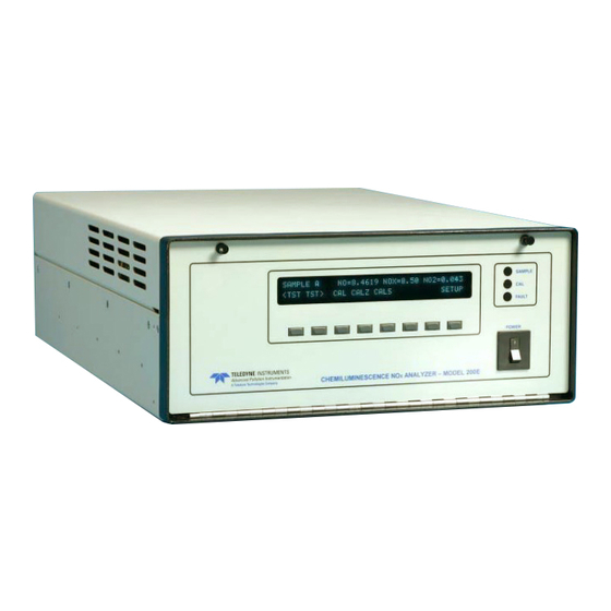
Page 26: M200E Layout
Model 200E Instruction Manual Getting Started 3.2. M200E Layout Figure 3-2 shows a top-down view of the analyzer. The shown configuration includes the Ethernet board, IZS option, zero-air scrubber and an additional sample dryer. See Chapter 5 for optional equipment. Figure 3-3 shows the rear panel configuration with optional zero-air scrubber mounted to it and two optional fittings for the IZS option. -
Page 27: Figure 3-3: M200E Rear Panel Layout
Getting Started Model 200E Instruction Manual Figure 3-3: M200E Rear Panel Layout Figure 3-4: M200E Front Panel Layout 044100102 Rev A... -
Page 28: Pneumatic Connections
Sample and calibration gases should only come into contact with PTFE (Teflon), FEP, glass or stainless steel materials. Figure 3-5 and Figure 3-6 illustrate the most common configurations for gas supply and exhaust lines to the Model 200E Analyzer. Appendix D contains more detailed pneumatic flow diagrams for the analyzer and its various (pneumatically related) options. -
Page 29: Span Gas Defined
Getting Started Model 200E Instruction Manual • Attach the 1/4" exhaust line to the exhaust port of the analyzer and to the inlet port of the pump. • Attach zero air and span gas supply lines as appropriate (Figure 3-5 and Figure 3-6) to the rear panel (Figure 3-3). -
Page 30: Zero Gas Defined
Model 200E Instruction Manual Getting Started For example, if the measurement is NO in ambient air between 0 and 500 ppb, an appropriate span gas would be NO in air at 400 ppb NO concentration (80% of maximum range). Even though NO gas in nitrogen could be used as a span gas, the matrix of the balance gas is different and may cause interference problems or yield incorrect calibrations. -
Page 31: Figure 3-6: Basic Pneumatic Connections For Units With Valve Options
Getting Started Model 200E Instruction Manual Zero/Span Valves – Option 50 Source of MODEL 700 SAMPLE Gas Gas Dilution Calibrator VENT if input is pressurized (with O generator option) Sample VENT MODEL Exhaust Pump 200E Span External Zero Zero Air... -
Page 32: Electrical Connections
Model 200E Instruction Manual Getting Started 3.4. Electrical Connections Refer to Figure 3-3 for the location of the rear panel electrical and pneumatic connections. 3.4.1. Power Connection Attach the power cord to the analyzer and plug it into a power outlet capable of carrying at least 10 A current at your AC voltage and that it is equipped with a functioning earth ground. -
Page 33: Figure 3-8: Status Output Connector
Getting Started Model 200E Instruction Manual Table 3-2: Analog Output Pin-Outs Analog Output Data Type Voltage Signal Current Signal V Out I Out + Ground I Out - V Out I Out + Ground I Out - V Out I Out +... -
Page 34: Figure 3-9: Control Input Connector
Model 200E Instruction Manual Getting Started If you wish to use the analyzer to remotely activate the zero and span calibration modes, several digital control inputs are provided through a 10-pin connector labeled CONTROL IN on the analyzer’s rear panel. -
Page 35: Ethernet Connection And Configuration
Getting Started Model 200E Instruction Manual to a serial port on your computer and set the computer serial port to 115000 baud transfer speed, 8 data bits, no parity, 1 stop bit and Xon/Xoff flow control. Use the APICOM remote control software that was included with the analyzer to connect to the instrument or use any terminal emulation program. -
Page 36: Warm-Up
Model 200E Instruction Manual Getting Started System waits 3 seconds then SELECT DESIRED FUNCTION automatically begins its initialization routine. No action required. START CHECKING FLASH STATUS System is checking the format of the instrument’s flash memory chip. If at this point,... -
Page 37: Table 3-6: Possible Warning Messages At Start-Up
Getting Started Model 200E Instruction Manual The following table includes a brief description of the various warning messages that may appear after the warm-up time. If warning messages persist after 30 minutes, investigate their cause using the troubleshooting guidelines in Chapter 11. To view and clear warning... -
Page 38: Functional Check
Model 200E Instruction Manual Getting Started 3.5.4. Functional Check After the analyzer’s components have warmed up for at least 30 minutes, verify that the software properly supports any hardware options that were installed. Check to make sure that the analyzer is functioning within allowable operating parameters. -
Page 39: Figure 3-11: M200E Pneumatic Diagram In Standard Configuration
Getting Started Model 200E Instruction Manual Figure 3-11: M200E Pneumatic Diagram In Standard Configuration 044100102 Rev A... -
Page 40: Figure 3-12: M200E Pneumatic Diagram With Options Installed
Model 200E Instruction Manual Getting Started Figure 3-12: M200E Pneumatic Diagram With Options Installed 044100102 Rev A... -
Page 41: First Calibration
Getting Started Model 200E Instruction Manual 3.6. First Calibration 3.6.1. Basic Calibration Procedure The initial calibration should be carried out using the 500 ppb range, a span gas with about 400 ppb NO and with the unit set for SINGLE range, which will enable you to compare your calibration results to the factory calibration as listed on the Final Test and Validation Data Sheet. -
Page 42: Interferences For No Measurements
(H O), ammonia (NH ), sulfur dioxide (SO ) and carbon dioxide (CO ) but the Model 200E has been designed to reject most of these interferences. Section 10.1.5 contains more detailed information on interferences. 044100102 Rev A... - Page 43 Ammonia is the most common interferent, which is converted to NO in the analyzer’s NO converter and creates a NO signal artifact. If the Model 200E is installed in an environment with high ammonia, steps should be taken to remove the interferent from the sample gas before it enters the reaction cell.
-
Page 44: Frequently Asked Questions & Glossary
Model 200E Instruction Manual Frequently Asked Questions & Glossary 4. FREQUENTLY ASKED QUESTIONS & GLOSSARY 4.1. Frequently Asked Questions The following list contains some of the most commonly asked questions relating to the Model 200E NO Analyzer. Q: Why is the ZERO or SPAN key not displayed during calibration? A: The M200E disables certain keys whenever the chosen value is out of range for that particular parameter. -
Page 45: Glossary
Acronym – A short form or abbreviation for a longer term. Often artificially made up of the first letters of the phrase’s words. APICOM – Name of a remote control program offered by Teledyne-API to its customers ASSY - Acronym for Assembly. - Page 46 Model 200E Instruction Manual Frequently Asked Questions & Glossary parts that acts as a computer hard disk drive under ! DOS with disk drive label “C”. DOC chips come with 8 mb space in the E-series analyzer standard configuration but are available in larger sizes DOS - Disk Operating System, the operating system underlying the M200E firmware.
- Page 47 Frequently Asked Questions & Glossary Model 200E Instruction Manual USER NOTES: 044100102 Rev A...
-
Page 48: Optional Hardware And Software
5. OPTIONAL HARDWARE AND SOFTWARE This section includes a descriptions of the hardware and software options available for the Model 200E Nitrogen Oxides Analyzer. For assistance with ordering these options please contact the sales department of Teledyne - Advanced Pollution Instruments at:... -
Page 49: Particulate Filter Kit (Option 42A)
Figure 3-12 shows the internal, pneumatic connections for a Model 200E with the zero/span valve option installed. Table 5-1 describes the state of each valve during the analyzer’s various operational modes. -
Page 50: Internal Zero/Span (Izs) (Option 51)
Model 200E Instruction Manual Optional Hardware and Software Table 5-1: IZS or Z/S Valve States Valve Port Connection Mode Valve Condition NO = normally open port NC = normally closed port COM = common port SAMPLE Sample/Cal Open to sample gas inlet... -
Page 51: Izs Permeation Tubes (Options 53 & 55)
Figure 3-12 shows the internal pneumatic connections for a Model 200E with IZS option installed. Table 5-1 shows the operational state of the valves associated with the IZS option during the analyzer’s various operational modes. -
Page 52: Scrubbers And Expendables
Model 200E Instruction Manual Optional Hardware and Software 5.6. Scrubbers and Expendables 5.6.1. Charcoal Scrubber (Option 64A) This kit includes a charcoal scrubber cartridge, which is used to remove NO from an exhaust port. Applications include, but are not limited to, the removal of NO... -
Page 53: M200E Expendables Kit (Option 42)
Optional Hardware and Software Model 200E Instruction Manual 5.6.5. M200E Expendables Kit (Option 42) This kit includes a recommended set of expendables for one year of operation of the M200E. See Appendix B for a detailed listing of the contents. -
Page 54: Sample Gas Conditioners (Options 86 & 88)
Model 200E Instruction Manual Optional Hardware and Software Figure 5-2: M200E Ethernet Card and Rear Panel With Ethernet Installed 5.8. Sample Gas Conditioners (Options 86 & 88) ® Several permeation devices using Nafion permeation gas exchange tubes are available for applications with high moisture and/or moderate levels of NH in the sample gas. -
Page 55: Manual On Cd (Part Number 044100200)
Optional Hardware and Software Model 200E Instruction Manual in which the sample gas has a significantly reduced or highly variable concentration of oxygen need to use the separate dryer option 86. The combination conditioner needs to be specified upon ordering the analyzer. -
Page 56: Operating Instructions
Model 200E Instruction Manual Operating Instructions 6. OPERATING INSTRUCTIONS To assist in navigating the analyzer’s software, a series of menu trees can be found in Appendix A of this manual along with an index of software commands and references to the respective manual sections. -
Page 57: Sample Mode
Operating Instructions Model 200E Instruction Manual The second operating mode is the SETUP mode. This mode is used for configuring various features and functions of the analyzer, such as the iDAS system, the analog output ranges, or the COM port settings. The SETUP mode is also used for performing various diagnostic tests during troubleshooting. -
Page 58: Table 6-2: Test Functions Defined
Model 200E Instruction Manual Operating Instructions Table 6-2: Test Functions Defined Display Parameter Units Description The full scale limit to which the analyzer’s analog outputs are currently set. This is not the physical range of the instrument. If PPB, PPM,... -
Page 59: Warning Messages
Operating Instructions Model 200E Instruction Manual 6.2.2. Warning Messages The most common instrument failures will be reported as a warning on the analyzer’s front panel and through the COM ports. Section 11.1 explains how to use these messages to troubleshoot problems. Section 3.5.3 shows how to view and clear warning messages. -
Page 60: Calibration Mode
Model 200E Instruction Manual Operating Instructions The CALS key is used to calibrate the span point of the analyzer. It is recommended that this span calibration is about 80-90% of full scale of the analyzer’s operating range. Chapter 7 details all calibration operations, Chapter 1 describes the zero/span valve and IZS options. - Page 61 Operating Instructions Model 200E Instruction Manual To enable or disable passwords, press the following keystroke sequence: SAMPLE RANGE = 500.0 PPB =XXX.X < TST TST > CAL SETUP SETUP X.X PRIMARY SETUP MENU Exit returns to SAMPLE display CFG DAS RNGE...
-
Page 62: Configuration Information (Cfg)
Model 200E Instruction Manual Operating Instructions 6.4.2. Configuration Information (CFG) Pressing the CFG key displays the instrument configuration information. This display lists the analyzer model, serial number, firmware revision, software library revision, operating system and other information. Use this information to identify the software and hardware when contacting customer service. -
Page 63: Setup - Range Configuration (Rnge)
Operating Instructions Model 200E Instruction Manual In order to compensate for CPU clocks which run fast or slow, there is a variable to speed up or slow down the clock by a fixed amount every day. To change this variable, press: SAMPLE RANGE = 500.0 PPB... -
Page 64: Physical And Analog Output Ranges
<TST> keys of the unit’s SAMPLE mode display. A4 is not available for the current loop option. 6.5.1. Physical and Analog Output Ranges Functionally, the model 200E NO analyzer has two physical ranges for determining NO , NO and NO concentrations. -
Page 65: Single Range Mode (Sngl)
Operating Instructions Model 200E Instruction Manual • Automatic range mode (AUTO) gives the analyzer the ability to report data through a low range and high range by automatically switching into the appropriate range as the concentrations change. Only one of the above range modes can be active at any time. To select output range types, use the following key sequences. - Page 66 Model 200E Instruction Manual Operating Instructions Setting analog range limits to different values does not affect the instrument’s calibration. To select the IND range mode, press the following keys: SAMPLE RANGE = 500.0 PPB NOX=X.X < TST TST > CAL...
-
Page 67: Auto Range Mode (Auto)
Operating Instructions Model 200E Instruction Manual 6.5.5. Auto Range Mode (AUTO) In AUTO range mode, the analyzer automatically switches the reporting range between two user-defined ranges (low and high). The same low and high span settings are applied equally to NO, NO and NO readings. -
Page 68: Dilution Ratio
Model 200E Instruction Manual Operating Instructions SAMPLE RANGE = 500.0 PPB NOX=X.X < TST TST > CAL SETUP PRIMARY SETUP MENU SETUP X.X CFG DAS RNGE PASS CLK MORE EXIT SETUP X.X RANGE CONTROL MENU EXIT returns to the main menu. - Page 69 Operating Instructions Model 200E Instruction Manual dilution set to 100, a 1 ppm gas can be used to calibrate a 100 ppm sample gas if the span gas is not routed through the dilution system. On the other hand, if a 100 ppm span gas is used, it needs to pass through the same dilution steps as the sample gas.
-
Page 70: Setup - Internal Variables (Vars)
Model 200E Instruction Manual Operating Instructions 6.6. Setup - Internal Variables (VARS) The M200E has several-user adjustable software variables, which define certain operational parameters. Usually, these variables are automatically set by the instrument’s firmware, but can be manually re-defined using the VARS menu. Table 6-5 lists all variables that are available within the 818 password protected level. - Page 71 Operating Instructions Model 200E Instruction Manual To access and navigate the VARS menu, use the following key sequence: SAMPLE RANGE = 500.0 PPB NOX=X.X < TST TST > CAL SETUP PRIMARY SETUP MENU SETUP X.X CFG DAS RNGE PASS CLK...
-
Page 72: Setup - Diagnostics (Diag)
Model 200E Instruction Manual Operating Instructions 6.7. Setup - Diagnostics (DIAG) A series of diagnostic tools is grouped together under the SETUP-MORE-DIAG menu. As these parameters are dependent on firmware revision, the menu trees are listed in detail in Appendix A. The individual parameters, however, are explained in more detail in the following section, indicated in Table 6-6. -
Page 73: Signal I/O
Operating Instructions Model 200E Instruction Manual To access the DIAG functions press the following keys: SAMPLE RANGE = 500.0 PPB NOX=X.X DIAG ANALOG I / O CONFIGURATION < TST TST > CAL SETUP PREV NEXT ENTR EXIT DIAG TEST CHAN OUTPUT... -
Page 74: Analog Output Step Test
Model 200E Instruction Manual Operating Instructions To enter the signal I/O test mode, press: SAMPLE RANGE = 500.0 PPB NOX=X.X DIAG SIGNAL I / O Use the NEXT & PREV keys to move between < TST TST > CAL SETUP... -
Page 75: Analog I/O Configuration
Operating Instructions Model 200E Instruction Manual 6.7.3. Analog I/O Configuration Table 6-7 lists the analog I/O functions that are available in the M200E. Table 6-7: DIAG - Analog I/O Functions Sub Menu Function AOUTS CALIBRATED: Shows the status of the analog output calibration (YES/NO) and initiates a calibration of all analog output channels. -
Page 76: Analog Output Signal Type And Range Selection
Model 200E Instruction Manual Operating Instructions The following DC current output limits apply to the current loop modules: Table 6-9: Analog Output Current Loop Range Range Minimum Output Maximum Output 0-20 mA 0 mA 20 mA These are the physical limits of the current loop modules, typical applications use 2-20 or 4-20 mA for the lower and upper limits. -
Page 77: Analog Output Calibration Mode
Operating Instructions Model 200E Instruction Manual 6.7.3.2. Analog Output Calibration Mode The analog outputs can be calibrated automatically or manually. In its default mode, the instrument is configured for automatic calibration of all channels. Manual calibration should be used for the 0.1V range or in cases where the outputs must be closely matched to the characteristics of the recording device. - Page 78 Model 200E Instruction Manual Operating Instructions DIAG ANALOG I / O CONFIGURATION EXIT to Return to the main PREV NEXT EXIT ENTR Sample Display DIAG AIO AOUTS CALIBRATED: NO < SET> EXIT Press SET> to select the Analog Output channel to be configured.
-
Page 79: Manual Analog Output Calibration
Operating Instructions Model 200E Instruction Manual 6.7.3.3. Manual Analog Output Calibration For highest accuracy, the voltages of the analog outputs can be manually calibrated. Note that outputs configured for 0.1V full scale should always be calibrated manually. Calibration is done through the instrument software with a voltmeter connected across the output terminals (Figure 6-3). -
Page 80: Analog Output Offset Adjustment
Model 200E Instruction Manual Operating Instructions FROM ANALOG I/O CONFIGURATION MENU DIAG AIO CONC_OUT_1 RANGE: 5V DIAG ANALOG I / O CONFIGURATION SET> EDIT EXIT PREV NEXT ENTR EXIT DIAG AIO CONC_OUT_1 REC OFS: 0 mV DIAG AIO AOUTS CALIBRATED: NO <... -
Page 81: Current Loop Output Adjustment
Operating Instructions Model 200E Instruction Manual FROM ANALOG I/O CONFIGURATION MENU DIAG ANALOG I / O CONFIGURATION PREV NEXT ENTR EXIT DIAG AIO AOUTS CALIBRATED: NO < SET SET> EXIT Press SET> to select the analog output channel to be configured. Then press... -
Page 82: Figure 6-3: Setup For Calibrating Current Outputs
Model 200E Instruction Manual Operating Instructions See Table 3-2 for pin assignments of the Analog Out connector on the rear panel. V OUT + I IN + V OUT - I IN - Recording Analyzer Device Figure 6-3: Setup for Calibrating Current Outputs CAUTION Do not exceed 60 V between current loop outputs and instrument ground. -
Page 83: Ain Calibration
Operating Instructions Model 200E Instruction Manual Table 6-12: Current Loop Output Calibration with Resistor Voltage for 2-20 mA Voltage for 4-20 mA Full scale (measured across resistor) (measured across resistor) 0.5 V 1.0 V 100% 5.0 V 5.0 V 6.7.3.6. AIN Calibration This is the sub-menu to conduct the analog input calibration. -
Page 84: Table 6-13: Test Parameters Available For Analog Output A4
Model 200E Instruction Manual Operating Instructions To activate the A4 channel and select a test function, follow this key sequence: SAMPLE RANGE = 500.0 PPB NOX=X.X Continue to press NEXT until … < TST TST > CAL SETUP DIAG TEST CHAN OUTPUT PRIMARY SETUP MENU SETUP X.X... -
Page 85: Optic Test
Operating Instructions Model 200E Instruction Manual 6.7.5. Optic Test The optic test function tests the response of the PMT sensor by turning on an LED located in the cooling block of the PMT (Fig. 10-15). The analyzer uses the light emitted from the LED to test its photo-electronic subsystem, including the PMT and the current to voltage converter on the pre-amplifier board. -
Page 86: Ozone Generator Override
Model 200E Instruction Manual Operating Instructions To activate the electrical test press the following keys. SAMPLE RANGE = 500.0 PPB NOX=X.X DIAG SIGNAL I / O < TST TST > CAL SETUP PREV NEXT JUMP ENTR EXIT SETUP X.X PRIMARY SETUP MENU Press NEXT until…... -
Page 87: Flow Calibration
Operating Instructions Model 200E Instruction Manual 6.7.8. Flow Calibration The flow calibration allows the user to adjust the values of the sample and ozone flow rates as they are displayed on the front panel and reported through COM ports to match the actual flow rate measured at the respective pneumatic ports. -
Page 88: Control Inputs
Model 200E Instruction Manual Operating Instructions The status outputs are accessed through a 12 pin connector on the analyzer’s rear panel labeled STATUS. The function of each pin is defined in Table 6-14. STATUS Figure 6-4: Status Output Connector Table 6-14: Status Output Pin Assignments... -
Page 89: Setup - Communication Ports (Comm)
Operating Instructions Model 200E Instruction Manual Table 6-15: Control Input Pin Assignments Input Status Condition when enabled EXTERNAL ZERO Zero calibration mode is activated. The mode field of the display will read ZERO CAL R . EXTERNAL SPAN Span calibration mode is activated. The mode field of the display will read SPAN CAL R . -
Page 90: Analyzer Id
Model 200E Instruction Manual Operating Instructions however, can be configured for half-duplex RS-485 communication or can be used for the T-API Ethernet interface card (optional equipment, Section 5.6.3). There are two options to connect multiple analyzers to a single computer terminal or data logging device over a single serial communications line. -
Page 91: Com Port Cable Connections
Operating Instructions Model 200E Instruction Manual CAUTION Cables that appear to be compatible because of matching connectors may incorpo- rate internal wiring that make the link inoperable. Check cables acquired from sources other than T-API for pin assignments before using. -
Page 92: Dte And Dce Communication
Model 200E Instruction Manual Operating Instructions Table 6-16: COM1 and COM2 DB-9 Pin Assignments Pin # COM1 (RS-232) COM2 (RS-232) COM2 (RS-485) Not used Not used Not used TRANSMIT DATA* RECEIVE DATA DATA - RECEIVE DATA* TRANSMIT DATA DATA +... -
Page 93: Table 6-17: Com Port Communication Modes
Operating Instructions Model 200E Instruction Manual Table 6-17: COM Port Communication Modes Mode Description Quiet mode Quiet mode suppresses any feedback from the analyzer (iDAS reports, and warning messages) to the remote device and is typically used when the port is communicating with a computer program such as APICOM. - Page 94 Model 200E Instruction Manual Operating Instructions To select a set of communication modes for a one of the COMM Ports, press: SAMPLE RANGE = 500.0 PPB NOX=X.X < TST TST > CAL SETUP PRIMARY SETUP MENU SETUP X.X CFG DAS RNGE PASS CLK...
-
Page 95: Com Port Baud Rate
Operating Instructions Model 200E Instruction Manual 6.9.7. COM Port Baud Rate To select the baud rate of one of the COM Ports, press: SAMPLE RANGE = 500.0 PPB NOX=X.X < TST TST > CAL SETUP PRIMARY SETUP MENU SETUP X.X... -
Page 96: Ethernet Port Configuration
The use of a terminal window or separate configuration program is needed for these low-level configuration changes. The iChip configuration utility is available at http://www.teledyne-api.com/software/ and provides a convenient, graphical user interface, which runs only on Microsoft Windows operating systems. - Page 97 Operating Instructions Model 200E Instruction Manual communicate with your local area network. To perform this configuration, you will need to get the following information from your network administrator: • Gateway IP address, typically a string of numbers with four packets of 1 to 3...
- Page 98 Model 200E Instruction Manual Operating Instructions Internet Configuration SAMPLE RANGE = 500.0 PPB O3 =XXX.X Keypad Functions < TST TST > CAL SETUP FUNCTION <CH Moves the cursor one PRIMARY SETUP MENU character to the left. SETUP X.X CH> Moves the cursor one...
-
Page 99: Hessen Mode Configuration
Operating Instructions Model 200E Instruction Manual Step three in the configuration process is to restart the pass-through mode for normal operation. SAMPLE RANGE = 500.0 PPB O3 =XXX.X SETUP X.X COMMUNICATIONS MENU < TST TST > CAL SETUP INET COM1... -
Page 100: Setup - Data Acquisition System (Das)
Model 200E Instruction Manual Operating Instructions 6.10. Setup - Data Acquisition System (DAS) The M200E analyzer contains a flexible and powerful, internal data acquisition system (iDAS) that enables the analyzer to store concentration and calibration data as well as a host of diagnostic parameters. -
Page 101: Idas Structure
Operating Instructions Model 200E Instruction Manual 6.10.1. iDAS Structure The iDAS is designed around the feature of a “record”. A record is a single data point of one parameter, stored in one (or more) data channels and generated by one of several triggering event. -
Page 102: Idas Parameters
Model 200E Instruction Manual Operating Instructions Table 6-20: iDAS Data Channel Properties Property Description Default Setting Range NAME The name of the data channel. “NONE” Up to 6 letters and digits (more with APICOM, but only the first six are displayed on the front panel). -
Page 103: Idas Triggering Events
Operating Instructions Model 200E Instruction Manual most common parameters are concentrations of measured gases (NO , NO and NO temperatures of heated zones (NO converter, reaction cell, box temperature…), pressures and flows of the pneumatic subsystem and other diagnostic measurements as well as calibration data (slope and offset) for each gas. -
Page 104: Configuring The Idas
Model 200E Instruction Manual Operating Instructions 6.10.2. Configuring the iDAS 6.10.2.1. Default M200E iDAS Configuration A set of default data channels has been included in the analyzer’s software for logging nitrogen oxides concentrations, calibration and predictive diagnostic data. These default... -
Page 105: Table 6-22: M200E Default Idas Configuration, Revision C.7
REFGND - AVG – 1 - OFF REF4096 - AVG - 1 - OFF Teledyne-API recommends to download and store CONC, CALDAT and ENGDAT data once per month for permanent documentation and future data analysis. Data can be most conveniently downloaded, graphed and stored using the APICOM remote control program. -
Page 106: Viewing Idas Data And Settings
Model 200E Instruction Manual Operating Instructions The default data channels can be used as they are, or they can be customized from the front panel or through APICOM to fit a specific application. The T-API website contains this default and other sample iDAS scripts for free download. We recommend that the user backs up any iDAS configuration and its data before altering it. -
Page 107: Editing Idas Data Channels
Operating Instructions Model 200E Instruction Manual 6.10.2.3. Editing iDAS Data Channels IDAS configuration is most conveniently done through the APICOM remote control program. The following list of key strokes shows how to edit using the front panel. SAMPLE RANGE = 500.0 PPB NOX=X.X... -
Page 108: Trigger Events
Model 200E Instruction Manual Operating Instructions To edit the name of a data channel, follow the above key sequence and then press: FROM THE PREVIOUS KEY SEQUENCE … SETUP X.X NAME:CONC <SET SET> PRINT EXIT EDIT ENTR accepts the new string SETUP X.X... -
Page 109: Editing Idas Parameters
Operating Instructions Model 200E Instruction Manual 6.10.2.5. Editing iDAS Parameters Data channels can be edited individually from the front panel without affecting other data channels. However, when editing a data channel, such as during adding, deleting or editing parameters, all data for that particular channel will be lost, because the iDAS can store only data of one format (number of parameter columns etc.) for any given channel. -
Page 110: Sample Period And Report Period
Model 200E Instruction Manual Operating Instructions To configure the parameters for a specific data parameter, press: FROM THE EDIT DATA PARAMETER MENU (see previous section) SETUP X.X 0) PARAM=PMTDET, MODE=INST PREV NEXT EXIT EDIT SETUP X.X PARAMETERS: PMTDET SET> EDIT EXIT SETUP X.X... - Page 111 Operating Instructions Model 200E Instruction Manual The REPORT PERIOD is typically used as the time interval between two permanently stored data points. The SAMPLE PERIOD is set to one minute by default and determines the frequency of data collection, i.e. how many times the iDAS records a parameter and stores it in a (volatile) data array for further processing and averaging.
-
Page 112: Number Of Records
Model 200E Instruction Manual Operating Instructions To define the SAMPLE or REPORT PERIOD, press SETUP-DAS-EDIT-ENTR and the following keys: FROM THE DAS PASSWORD MENU Edit Data Channel Menu SETUP X.X 0) CONC: ATIMER, Use the PREV and NEXT Exits to the main... -
Page 113: Report Function
Operating Instructions Model 200E Instruction Manual FROM THE DAS PASSWORD MENU Edit Data Channel Menu SETUP X.X 0) CONC: ATIMER, Exits to the main Data Acquisition PREV NEXT EDIT PRNT EXIT menu SETUP X.X NAME:CONC <SET SET> EDIT PRINT EXIT Press SET>... -
Page 114: Compact Report
Model 200E Instruction Manual Operating Instructions To enable automatic COM port reporting, press SETUP-DAS-ENTR and then: FROM THE DAS PASSWORD MENU Edit Data Channel Menu SETUP X.X 0) CONC: ATIMER, Exits to the main Data Acquisition PREV NEXT EDIT PRNT... -
Page 115: Holdoff Feature
Operating Instructions Model 200E Instruction Manual To disable a data channel, press SETUP-DAS-ENTR and the following keys: FROM THE DAS PASSWORD MENU Edit Data Channel Menu SETUP X.X 0) CONC: ATIMER, Exits to the main Data Acquisition PREV NEXT EDIT... -
Page 116: Remote Idas Configuration
Model 200E Instruction Manual Operating Instructions 6.10.3. Remote iDAS Configuration Editing channels, parameters and triggering events as described in Section 6.9.10 is much more conveniently done in one step through the APICOM remote control program using the graphical interface shown in Figure 6-6. Refer to the next Section 6.11 for details on remote access to the M200E analyzer. -
Page 117: Remote Operation Of The Analyzer
6.11.1. Basic Operation 6.11.1.1. Terminal Operating Modes The Model 200E can be remotely configured, calibrated or queried for stored data through the serial ports. As terminals and computers use different communication schemes, the analyzer supports two communicate modes specifically designed to interface with these two types of devices. -
Page 118: Help Commands In Terminal Mode
Computer mode is used when the analyzer is connected to a computer with a dedicated interface program such as APICOM. More information regarding APICOM can be found in later in this section or on the T-API website at http://www.teledyne- api.com/software/apicom/. -
Page 119: Data Types
Operating Instructions Model 200E Instruction Manual COMMAND is the command designator: This string is the name of the command being issued (LIST, ABORT, NAME, EXIT, etc.). Some commands may have additional arguments that define how the command is to be executed. -
Page 120: Status Reporting
Model 200E Instruction Manual Operating Instructions 6.11.2. Status Reporting Reporting of status messages as an audit trail is one of the three principal uses for the RS-232 interface (the other two being the command line interface for controlling the instrument and the download of data in electronic format). You can effectively disable the reporting feature by setting the interface to quiet mode (Section 6.9.6, Table 6-18). -
Page 121: Com Port Password Security
• LOGON SUCCESSFUL - Correct password given. • LOGON FAILED - Password not given or incorrect. • LOGOFF SUCCESSFUL - Connection terminated successfully. To log on to the model 200E analyzer with SECURITY MODE feature enabled, type: 044100102 Rev A... -
Page 122: Apicom Remote Control Program
Model 200E Instruction Manual Operating Instructions LOGON 940331 940331 is the default password. To change the default password, use the variable RS232_PASS issued as follows: V RS232_PASS=NNNNNN Where N is any numeral between 0 and 9. 6.11.5. APICOM Remote Control Program... -
Page 123: Additional Communications Documentation
Part Number Tool Online* Multi-drop RS-232 Multi-drop Documentation 021790000 DAS Manual Detailed description of the iDAS 028370000 APICOM APICOM User Manual 039450000 Hessen Hessen Protocol 4.0 Manual Addendum 045850000 protocol * These documents can be downloaded at http://www.teledyne-api.com/manuals/ 044100102 Rev A... -
Page 124: Calibration Procedures
If this has not been done, please do so before continuing (Section 6.5 for instructions). 7.1.1. Required Equipment, Supplies, and Expendables Calibration of the Model 200E analyzer requires a certain amount of equipment and supplies. These include, but are not limited to, the following: •... -
Page 125: Permeation Tubes
The currently programmed CE is recorded along with the calibration data in the iDAS for documentation and performance analysis (Section 6.10.2.1). The following procedure will cause the Model 200E to automatically calculate the current conversion efficiency. Step one is to connect a source of calibrated NO span gas as shown below. -
Page 126: Figure 7-1: Gas Supply Setup For Determination Of No
Model 200E Instruction Manual Calibration Procedures Calibrated Source of (high SAMPLE Gas Gas Dilution concentration) removed Calibrator during (with O generator procedure option) VENT Zero Air Source Sample MODEL Exhaust Pump Span 200E Zero Air Figure 7-1: Gas Supply Setup for Determination of NO... -
Page 127: Manual Calibration
ENTR EXIT 7.2. Manual Calibration The following section describes the basic method for manually calibrating the Model 200E analyzer. A note on the difference between a calibration and calibration check: pressing the ENTR key during the following procedures recalculates the stored values for OFFSET and SLOPE (instrument response curve) and alters the instrument’s calibration. -
Page 128: Connect Zero Air And Span Gases To The Analyzer
Model 200E Instruction Manual Calibration Procedures 7.2.1. Connect Zero Air and Span Gases to the Analyzer Source of sample gas removed Calibrated NO during MODEL 700 Gas (high calibration Dilution concentration) Calibrator (with O generator option) Sample MODEL 701 Vent excess gas... -
Page 129: Perform Zero/Span Calibration
Calibration Procedures Model 200E Instruction Manual NOTE The expected concentrations for both NO and NO are usually set to the same value unless the conversion efficiency is not equal to 1.000 or not entered properly in the conversion efficiency setting. When setting expected concentration values, consider impurities in your span gas source (NO often contains 1-3% NO and vice versa). -
Page 130: Calibration Checks
Model 200E Instruction Manual Calibration Procedures If the ZERO or SPAN keys are not displayed during zero or span calibration, the measured concentration value is too different from the expected value and the analyzer does not allow to zero or span the instrument. Consult Section 11.3 for calibration problems. - Page 131 Calibration Procedures Model 200E Instruction Manual gas inlets rather than through the sample inlet and that the zero and span operations are initiated directly and independently with dedicated keys CALZ and CALS. Connect the sources of zero air and span gas to the respective ports on the rear panel (Figure 3-2) to follow the setup in Figure 7-4.
-
Page 132: Calibration With Izs Option
Model 200E Instruction Manual Calibration Procedures 7.5. Calibration with IZS Option When using the IZS option to calibrate the M200E, the analyzer’s CAL_ON_NO2 feature must be turned on. This feature enables a continuous zero gas flow across the IZS permeation tube and through the NO converter (Figure 3-11). - Page 133 Calibration Procedures Model 200E Instruction Manual Set the expected NO and NO values according to Section 7.2. Perform the zero point calibration: SAMPLE RANGE = 500.0 PPB NOX= X.X Set the Display to show the NOX STB test function. < TST TST >...
-
Page 134: Calibration Checks With Izs Or Zero/Span Valves
Model 200E Instruction Manual Calibration Procedures SAMPLE RANGE = 500.0 PPB NOX= X.X Set the Display to show the NOX STB test function. < TST CALZ CALS SETUP TST > SAMPLE NOX STB=XXX.X PPB NOX=X.X < TST TST > CAL CALZ... -
Page 135: Calibration With Independent Or Auto Ranges
EXIT SAMPLE display 7.7. Calibration With Independent or AUTO Ranges Additional considerations apply when calibrating a Model 200E with reporting ranges set to AUTO (automatic) or IND (independent) mode (Sections 6.5.4 and 6.5.5). 7.7.1. Calibration in AUTO Range Mode If the analyzer is operated in AUTO range mode, the high and low ranges must be indepen- dently calibrated. -
Page 136: Independent Range Mode
Model 200E Instruction Manual Calibration Procedures SAMPLE RANGE = 500.0 PPB NOX=X.XX < TST TST > CAL CALZ CALS SETUP SAMPLE RANGE TO CAL: LOW HIGH ENTR SETUP SAMPLE RANGE TO CAL: HIGH LOW HIGH SETUP ENTR ZERO CAL M RANGE = 500.0 PPB... -
Page 137: Automatic Calibration (Autocal)
Calibration Procedures Model 200E Instruction Manual 7.8. Automatic Calibration (AutoCal) The AutoCal feature allows unattended, periodic operation of the zero/span valve options by using the analyzer’s internal time of day clock. The AutoCal feature is only available on the front panel menu (ACAL) if either the zero/span valve or the IZS option is installed. -
Page 138: Table 7-4: Example Auto-Cal Sequence
Model 200E Instruction Manual Calibration Procedures NOTE The CALIBRATE attribute (formerly called “dynamic calibration”) must always be set to OFF for analyzers used in US EPA controlled applications that have IZS option installed. Calibration of instruments used in US EPA related applications should only be performed using external sources of zero air and span gas with an accuracy traceable to EPA or NIST standards and supplied through the analyzer’s... -
Page 139: Calibration Quality Analysis
Calibration Procedures Model 200E Instruction Manual To program the sample sequence shown above, follow this flow chart: SAMPLE RANGE = 500.0 PPB NOX=X.X SETUP C.4 STARTING TIME:14:15 < TST TST > CAL CALZ CZLS SETUP <SET SET> EDIT EXIT PRIMARY SETUP MENU SETUP X.X... -
Page 140: Table 7-5: Calibration Data Quality Evaluation
Model 200E Instruction Manual Calibration Procedures perform this quality evaluation, you will need to record the values of the following test functions (Section 6.2.1 or Appendix A-3), all of which are automatically stored in the iDAS channel CALDAT for data analysis, documentation and archival. - Page 141 Calibration Procedures Model 200E Instruction Manual USER NOTES: 044100102 Rev A...
-
Page 142: Epa Protocol Calibration
Model 200E Instruction Manual EPA Protocol Calibration 8. EPA PROTOCOL CALIBRATION To ensure high quality, accurate measurements at all times, the M200E analyzer must be calibrated prior to use. A quality assurance program centered on this aspect and including attention to the built-in warning features of the analyzer, periodic inspection, regular zero/span checks, regular evaluation of test parameters for predictive diagnostics and data analysis and routine maintenance of the instrument are paramount to achieving this goal. -
Page 143: Table 8-1: Activity Matrix For Epa Calibration Equipment And Supplies
EPA Protocol Calibration Model 200E Instruction Manual Table 8-1: Activity Matrix for EPA Calibration Equipment and Supplies Equipment/ Frequency And Method Action If Requirements Acceptance Limits Supplies Of Measurement Are Not Met Recorder Compatible with output signal Check upon receipt Return equipment to of analyzer;... -
Page 144: Gas Phase Titration (Gpt)
Model 200E Instruction Manual EPA Protocol Calibration 8.2. Gas Phase Titration (GPT) 8.2.1. GPT Principle of Operation Gas phase titration (GPT) is recommended for calibration of the M200E. Those using a NO permeation tube should refer to the CFR The principle of GPT is based on the rapid gas phase reaction between NO and O... - Page 145 EPA Protocol Calibration Model 200E Instruction Manual If more than one analyzer is to be calibrated at the same time, multiply F by the number of analyzers. Calculate the NO concentration [NO] needed to approximate 90% of the URL of the NO...
-
Page 146: Example Gpt Calculation
Model 200E Instruction Manual EPA Protocol Calibration 8.2.3. Example GPT Calculation Following is an example calculation that can be used to determine whether an existing GPT calibrator will meet the required conditions for a specific calibration. For this example, it is... -
Page 147: Multipoint Calibration Procedure
EPA Protocol Calibration Model 200E Instruction Manual Verify the dynamic parameter specification (P ) of the calibrator reaction cell using Equation 8-6: × × − Calculate the diluent air flow (F ) required at the mixing chamber, using Equation 8-7:... -
Page 148: Zero Calibration
Model 200E Instruction Manual EPA Protocol Calibration Figure 8-1: GPT Calibration System Converter efficiency should be set prior to calibration since its value is used in the computation of the NO and NO concentration outputs. The analyzer should be calibrated on the same range used for monitoring. -
Page 149: Calibration
EPA Protocol Calibration Model 200E Instruction Manual concentration to the NO concentration to get the NO concentration for calibration. Calculate the exact NO and NO concentrations as follows: Eq 8-8 Enter the respective concentrations using the procedure in Section 7.2. The expected span concentrations need not be re-entered each time a calibration is performed unless they are changed. -
Page 150: Calibration Frequency
Model 200E Instruction Manual EPA Protocol Calibration Second, turn on and adjust the O generator in the calibrator to produce sufficient O decrease the NO concentration to about 10% of full scale. This will be equivalent to 80% of the URL of the NO channel. -
Page 151: Table 8-3: Definition Of Level 1 And Level 2 Zero And Span Checks
EPA Protocol Calibration Model 200E Instruction Manual Essential to quality assurance are scheduled checks for verifying the operational status of the monitoring system. The operator should visit the site at least once each week. Every two weeks a Level 1 zero and span check must be made on the analyzer. Level 2 zero and span checks should be conducted at a frequency desired by the user. -
Page 152: Summary Of Quality Assurance Checks
Model 200E Instruction Manual EPA Protocol Calibration 8.6. Summary of Quality Assurance Checks The following items should be checked on a regularly scheduled basis to assure high quality data from the M200E. See Table 8-4 for a summary of activities; also the QA Handbook should be checked for specific procedures. -
Page 153: Zero/Span Check Procedures
EPA Protocol Calibration Model 200E Instruction Manual 8.7.1. Zero/Span Check Procedures The Zero and span calibration can be checked in a variety of different ways. They include: • Manual zero/span checks can be done from the front panel keyboard. The procedure is in Section 7.3 or 7.6 of this manual. -
Page 154: Certification Procedures Of Working Standards
Model 200E Instruction Manual EPA Protocol Calibration Evidence of good quality data includes documentation of the quality control checks and the independent audits of the measurement process by recording data on specific forms or on a quality control chart and by using materials, instruments, and measurement procedures that can be traced to appropriate standards of reference. - Page 155 EPA Protocol Calibration Model 200E Instruction Manual Triangle Park, NC. 83 pages, December 1975. Available online at http://www.epa.gov/ttn/amtic/files/ambient/criteria/reldocs/4-75-003.pdf. 3. Environmental Protection Agency, Title 40, Code of Federal Regulations, Part 58, Appendix A, Measurement Principle and Calibration Procedure for the Measurement...
-
Page 156: Instrument Maintenance
Model 200E Instruction Manual Instrument Maintenance 9. INSTRUMENT MAINTENANCE Predictive diagnostic functions including data acquisition, failure warnings and alarms built into the analyzer allow the user to determine when repairs are necessary without perform- ing unnecessary, preventative maintenance procedures. There is, however, a minimal number of simple procedures that, when performed regularly, will ensure that the analyzer continues to operate accurately and reliably over its lifetime. - Page 157 Instrument Maintenance Model 200E Instruction Manual Table 9-1: M200E Preventive Maintenance Schedule (continued) Check Yes on Every 3 converter conversion change, 9.3.8 months efficiency else no External zero Exchange Every 3 air scrubber 9.3.7 chemical months (optional) When External dryer...
-
Page 158: Predictive Diagnostics
Drift of instrument response; clean RCEL NO CONC constant time window, change O air filter chemical. concentration 9.3. Maintenance Procedures The following procedures need to be performed regularly as part of the standard maintenance of the Model 200E. 044100102 Rev A... -
Page 159: Changing The Sample Particulate Filter
Instrument Maintenance Model 200E Instruction Manual 9.3.1. Changing the Sample Particulate Filter The particulate filter should be inspected often for signs of plugging or excess dirt. It should be replaced according to the service interval in Table 9-1 even without obvious signs of dirt. -
Page 160: Changing The O Dryer Particulate Filter
Model 200E Instruction Manual Instrument Maintenance • To fulfill CE Mark safety requirements, the front panel locking screw must be installed at all times during operation of the analyzer. • Re-start the analyzer. 9.3.2. Changing the O Dryer Particulate Filter ©... -
Page 161: Changing The Ozone Filter Chemical
Instrument Maintenance Model 200E Instruction Manual 9.3.3. Changing the Ozone Filter Chemical The O filter is located between the O generator and the reaction cell and cleans the O stream from solid and liquid contaminants that are created inside the O generator. -
Page 162: Rebuilding The External Sample Pump
AutoZero value, slowly diminishing over time. Until diminished, this will cause large negative offsets on calibration and a changing calibration over time. It may take one week to clean the material properly, hence, we recommend to use genuine Teledyne-API refill kits to ensure minimum downtimes. •... -
Page 163: Changing The Pump And Izs Dust Filters
Instrument Maintenance Model 200E Instruction Manual locations). A pump rebuild kit is available from the factory. Appendix B of this manual lists the part numbers of the pump rebuild kit. Instructions and diagrams are included in the kit. A flow and leak check after rebuilding the sample pump is recommended. A span check and re-calibration after this procedure is necessary as the response of the analyzer changes with the RCEL pressure. -
Page 164: Changing The External Zero Air Scrubber
Model 200E Instruction Manual Instrument Maintenance • Remove the top layer of insulation if necessary. • Unscrew the black aluminum cover of the IZS oven (3 screws) using a medium Phillips-head screw driver. Leave the fittings and tubing connected to the cover. -
Page 165: Changing The No Converter
Instrument Maintenance Model 200E Instruction Manual • Adjust the scrubber cartridge such that it does not protrude above or below the analyzer in case the instrument is mounted in a rack. If necessary, squeeze the clips for a tighter grip on the cartridge. -
Page 166: Cleaning The Reaction Cell
Model 200E Instruction Manual Instrument Maintenance • Remove the tube fittings from the converter. • Disconnect the power and the thermocouple of the converter. Unscrew the grounding clamp of the power leads with a Phillips-head screw driver. Figure 9-5: NO Converter Assembly •... -
Page 167: Figure 9-6: Reaction Cell Assembly
Instrument Maintenance Model 200E Instruction Manual all. To clean the reaction cell, it is necessary to remove it from the sensor housing. refer to Section 11.6.6. for an overview of the entire sensor assembly. Use the following guide to clean the reaction cell: •... -
Page 168: Cleaning Or Changing Critical Flow Orifices
Model 200E Instruction Manual Instrument Maintenance • Reassemble in proper order and re-attach the reaction cell to the sensor housing. Reconnect pneumatics and heater connections, then re-attach the pneumatic sensor assembly and the cleaning procedure is complete. • After cleaning the reaction cell, it is also recommended to exchange the ozone supply air filter chemical as described in Section 9.3.3. -
Page 169: Checking For Light Leaks
Instrument Maintenance Model 200E Instruction Manual • Turn off power to the instrument and vacuum pump. Remove the analyzer cover and locate the reaction cell (Figure 9-6, Figure 11-7 and Figure 3-7). • Unscrew the 1/8” sample and ozone air tubes from the reaction cell •... -
Page 170: Theory Of Operation
Model 200E Instruction Manual Theory of Operation 10. THEORY OF OPERATION The M200E Nitrogen Oxides Analyzer is a microprocessor controlled instrument that determines the concentration of nitric oxide (NO), total nitrogen oxides (NO , the sum of NO and NO ) and nitrogen dioxide (NO ) in a sample gas drawn through the instrument. -
Page 171: Nox
Theory of Operation Model 200E Instruction Manual supplies the reaction cell with a large, constant excess of ozone (about 3000-5000 ppm) from the internal ozone generator. Figure 10-1: M200E Sensitivity Spectrum However, only about 20% of the NO that is formed through reaction 10-1 is in the excited state. -
Page 172: Chemiluminescence Detection
Model 200E Instruction Manual Theory of Operation heated to a temperature of 315° C. The heated molybdenum reacts with NO in the sample gas and produces a variety of molybdenum oxides and NO according to Equation 10-4. → ° Eq 10-4... -
Page 173: Optical Filter
Theory of Operation Model 200E Instruction Manual more details), is converted to a voltage and amplified by the preamplifier board and then reported to the motherboard’s analog inputs. Figure 10-3: Reaction Cell with PMT Tube 10.1.3.2. Optical Filter Another critical component in the method by which your M200E detects chemiluminescence is the optical filter that lies between the reaction cell and the PMT (Figure 10-2). -
Page 174: Measurement Interferences
Model 200E Instruction Manual Theory of Operation Figure 10-4: Reaction Cell During the AutoZero Cycle. 10.1.5. Measurement Interferences It should be noted that the chemiluminescence method is subject to interferences from a number of sources. The M200E has been successfully tested for its ability to reject interference from most of these sources. -
Page 175: Table 10-1: List Of Interferents
Theory of Operation Model 200E Instruction Manual The influence of water vapor on the M200E measurement can be eliminated with an optional, internal sample gas dryer. The concentrations of N and O are virtually constant in ambient air measurements, hence provide a constant amount of quenching and the interference of varying CO amounts is negligible at low concentrations. -
Page 176: Light Leaks
Model 200E Instruction Manual Theory of Operation ence. For those applications, we recommend to use other analyzer models. Please consult sales or our website. 10.1.5.3. Light Leaks The M200E sensitivity curve includes a small portion of the visible light spectrum (Figure 10-3), hence, it is important to make sure than the reaction cell is completely sealed with respect to light. -
Page 177: Sample Gas Flow
Theory of Operation Model 200E Instruction Manual See Section 3.1 for information on connecting and operating the external pump. Figure 10-5: External Pump Pack Finally, the M200E requires a steady, high underpressure, which cannot be achieved reliably over extended periods of time with small vacuum pumps. The external pump used for the M200E has a very long lifetime and duty cycle and provides a very good vacuum for its entire lifetime. -
Page 178: Sample Particulate Filter
Model 200E Instruction Manual Theory of Operation Table 10-2: M200E Valve Cycle Phases Phase NO/ NO Autozero Time Activity Figure Valve Valve Index Status Status Open to Open to 0 - 2 s Wait period (NO dwell time). Figure 10-2... -
Page 179: Ozone Gas Air Flow
Theory of Operation Model 200E Instruction Manual 10.2.4. Ozone Gas Air Flow The excess ozone needed for reaction with NO in the reaction cell is generated inside the analyzer because of the instability and toxicity of ozone. Besides the ozone generator itself, this requires a dry air supply and filtering of the gas before it is introduced into the reaction cell. -
Page 180: Perma Pure Dryer
Model 200E Instruction Manual Theory of Operation The M200E utilizes a dual-dielectric design. This method utilizes a glass tube with hollow walls. The outermost and innermost surfaces are coated with electrically conductive material. The air flows through the glass tube, between the two conductive coatings, in effect creating a capacitor with the air and glass acting as the dielectric. -
Page 181: Ozone Supply Air Filter
Theory of Operation Model 200E Instruction Manual components of the gases to be dried are usually unaffected. The chemical reaction is based on hydrogen bonds between the water molecule and the Nafion material. Other small polar gases that are capable of hydrogen bonds can be absorbed this way, too, such as ammonia ) and some low molecular amines. -
Page 182: Ozone Scrubber
Model 200E Instruction Manual Theory of Operation sensitivity drift, nitric acid is a very aggressive compound, which can deteriorate the analyzer’s components. In order to remove these chemical byproducts from the O stream, the output of the O generator flows through a special filter between the generator and the reaction cell. -
Page 183: Figure 10-9: Location Of Flow Control Assemblies
Theory of Operation Model 200E Instruction Manual variations only travel at the speed of sound themselves and are therefore cancelled out at the downstream exit of the critical flow orifice. Figure 10-9: Location of Flow Control Assemblies Figure 10-10: Flow Control Assembly & Critical Flow Orifice The actual flow rate of gas through the orifice depends entirely on the size and shape of the aperture in the orifice and the upstream pressure. -
Page 184: Table 10-3: M200E Gas Flow Rates
Model 200E Instruction Manual Theory of Operation upstream pressure, the more gas molecules pass through the orifice. The flow rate of the gas is also unaffected by small degradations in pump efficiency due to age as long as the 2:1 pressure difference is maintained. -
Page 185: Pneumatic Sensors
Theory of Operation Model 200E Instruction Manual 10.2.10. Pneumatic Sensors NOTE The M200E displays all pressures in inches of mercury absolute (in-Hg-A), i.e. absolute pressure referenced against zero (a perfect vacuum). The M200E uses three pneumatic sensors to verify gas streams. These sensors are located on a printed circuit assembly, called the pneumatic pressure/flow sensor board, located just behind the sensor assembly. -
Page 186: Electronic Operation
Model 200E Instruction Manual Theory of Operation GEN OFF, is displayed. This flow measurement is viewable through instrument’s front panel display as the test function OZONE FL. 10.3. Electronic Operation Figure 10-11 shows a block diagram of the major electronic components of the M200E. -
Page 187: Cpu
Theory of Operation Model 200E Instruction Manual T-API. It communicates with the user, receives data from and issues commands to a variety of peripheral devices through the motherboard, the main printed circuit assembly on the rear panel (Figure 3-2). 10.3.1. CPU The CPU is a low power (5 VDC, 0.8A max), high performance, 386-based microcomputer... -
Page 188: Disk On Chip
Model 200E Instruction Manual Theory of Operation the chassis on its own mounting bracket) to control the function of heaters and valves. The CPU includes two types of non-volatile data storage, one disk-on-chip and one or two flash chips. 10.3.1.1. Disk On Chip... -
Page 189: Photo Multiplier Tube (Pmt)
Theory of Operation Model 200E Instruction Manual 10.3.2.2. Photo Multiplier Tube (PMT) The M200E uses a photo multiplier tube (PMT) to detect the chemiluminescence created by the reaction of NO with O in the reaction cell. A typical PMT is a vacuum tube containing a variety of specially designed electrodes (Figure 10-13). -
Page 190: Tec Control Board
Model 200E Instruction Manual Theory of Operation The core part of the M200E PMT cooling system is a thermoelectric cooler (TEC), which keeps the PMT temperature at a constant, low level (7±2°C) for optimum performance. Thermoelectric coolers are solid state (semi-conductor) heat pumps, which transfer heat from one side to the other when a DC current is passed through its circuits. -
Page 191: Pneumatic Sensor Board
Theory of Operation Model 200E Instruction Manual Figure 10-14: PMT Preamp Block Diagram 10.3.3. Pneumatic Sensor Board The flow and pressure sensors of the M200E are located on a printed circuit assembly just behind the PMT sensor. Refer to Section 11.5.15 for a figure and on how to test this assembly. -
Page 192: Relay Board
Model 200E Instruction Manual Theory of Operation 10.3.4. Relay Board The relay board is the central switching and power distribution unit of the analyzer. It contains power relays, valve drivers and status LEDs for all heated zones and valves, as well as thermocouple amplifiers, power distribution connectors and the two switching power supplies of the analyzer. -
Page 193: Motherboard
Theory of Operation Model 200E Instruction Manual 10.3.5. Motherboard This is the largest electronic assembly in the analyzer and is mounted to the rear panel as the base for the CPU board and all I/O connectors. This printed circuit assembly provides a... -
Page 194: Thermistor Interface
Model 200E Instruction Manual Theory of Operation current temperature of the NO converter. It is also stored in the iDAS and reported as test function MOLY TEMP. • The sample gas pressure is measured upstream of the reaction cell, stored in the iDAS and reported as SAMPLE. -
Page 195: External Digital I/O
Theory of Operation Model 200E Instruction Manual The output labeled A4 can be set by the user (Section 6.7.2) to carry the signal of any of these TEST parameters: none , PMT DETECTOR, OZONE FLOW, SAMPLE FLOW, SAMPLE PRESSURE, RCELL PRESSURE, RCELL TEMP, MANIFOLD TEMP, IZS TEMP, CONV TEMP, PMT TEMP, BOX TEMP, HVPS VOLTAGE. -
Page 196: Communications Interface
Model 200E Instruction Manual Theory of Operation of the instrument. From there, it is routed through the ON/OFF switch located in the lower right corner of the front panel and back to the relay board, which carries the switching power supplies. -
Page 197: Front Panel
Theory of Operation Model 200E Instruction Manual and display. Direct communication with the CPU is also available through the analyzer’s RS- 232 and RS-485 ports. The analyzer can also send and receive different kinds of information through its external, digital I/O connectors and through the four analog outputs, all located on the rear panel. -
Page 198: Keypad
Model 200E Instruction Manual Theory of Operation queries for operation data about the instrument. During interactive tasks, such as instru- ment calibration or certain diagnostic procedures, the instrument’s response messages are also displayed here. Concentration Field: The far right portion of the top line of text displays the concentration of the sample gas currently being measured by the analyzer. -
Page 199: Software Operation
Theory of Operation Model 200E Instruction Manual is handle by the instrument’s I C bus. The CPU controls the clock signal and determines when the various devices on the bus are allowed to talk or required to listen. Data packets are labeled with addresses that identify for which device the information is intended. -
Page 200: Calibration - Slope And Offset
Model 200E Instruction Manual Theory of Operation stable readings and averages out a considerable amount of random noise for an overall less noisy concentration reading. If the filter detects rapid changes in concentration the filter reduces the averaging to only 6 samples or about 48 seconds to allow the analyzer to respond more quickly. -
Page 201: Temperature/Pressure Compensation (Tpc)
Theory of Operation Model 200E Instruction Manual Instrument slope and offset values recorded during the last calibration can be viewed on the front panel. NO SLOPE, NOX SLOPE, NO OFFS and NOX OFFS are four of the test parameters accessible through the <TST TST> buttons. -
Page 202: Converter Efficiency Compensation
Model 200E Instruction Manual Theory of Operation The preset gain parameters are set at the factory and may vary from analyzer to analyzer. Section 6.5 describes the method for enabling/disabling the TPC feature. 10.4.4. NO Converter Efficiency Compensation Over time, the molybdenum in the NO... - Page 203 Theory of Operation Model 200E Instruction Manual USER NOTES: 044100102 Rev A...
-
Page 204: Troubleshooting & Repair
Model 200E Instruction Manual Troubleshooting & Repair 11. TROUBLESHOOTING & REPAIR This section contains a variety of methods for identifying and solving performance problems with the analyzer. NOTE The operations outlined in this chapter must be performed by qualified maintenance personnel only. -
Page 205: Warning Messages
Troubleshooting & Repair Model 200E Instruction Manual and sub-assemblies in the analyzer. See the wiring interconnect diagram (document 04504) and interconnect list (document 04496) in Appendix D. 11.1.1. Warning Messages The most common and/or serious instrument failures will result in a warning message displayed on the front panel. -
Page 206: Using The Diagnostic Signal I/O Function
Model 200E Instruction Manual Troubleshooting & Repair The acceptable ranges for these test functions are listed in Appendix A-3. The actual values for these test functions on checkout at the factory were also listed in the Final Test and Validation Data Sheet, which was shipped with the instrument. Values outside the acceptable ranges indicate a failure of one or more of the analyzer’s subsystems. -
Page 207: Status Led's
Troubleshooting & Repair Model 200E Instruction Manual • All of the components and functions that are normally under instrument control can be manually changed. • Analog and digital output signals can be manually controlled. This allows to systematically observe the effect of these functions on the operation of the analyzer. -
Page 208: Cpu Status Indicator
Model 200E Instruction Manual Troubleshooting & Repair Figure 11-3: Motherboard Watchdog Status Indicator 11.1.4.2. CPU Status Indicator The CPU board has two red LEDs, the lower of which is the watchdog timer (the device that pulses the motherboard watchdog). This LED is labeled LED2 and blinks about twice per second (twice as fast as the motherboard LED) when operating normally. -
Page 209: Figure 11-4: Relay Board Pca
Troubleshooting & Repair Model 200E Instruction Manual Figure 11-4: Relay Board PCA To enter the signal I/O test mode to manually control I/O functions such as valves and heaters, press the following keys while observing the relay board LEDs when toggling: SAMPLE RANGE = 500.0 PPB... -
Page 210: Gas Flow Problems
Model 200E Instruction Manual Troubleshooting & Repair Table 11-2: Relay Board Status LEDs Color Function Fault Status Indicated Failure(s) LED Row 1 (center of board) Watchdog Circuit; I C bus Continuously Failed or halted CPU; faulty operation. ON or OFF motherboard, keyboard, relay board;... -
Page 211: Zero Or Low Flow Problems
Troubleshooting & Repair Model 200E Instruction Manual • Flow is zero (no flow) When troubleshooting flow problems, it is essential to confirm the actual flow rate without relying on the analyzer’s flow display. The use of an independent, external flow meter to perform a flow check as described in Section 6.7.8 is essential. -
Page 212: Ozone Flow Is Zero Or Low
Model 200E Instruction Manual Troubleshooting & Repair path and vacuum, most likely through the Perma Pure dryer flow paths. See troubleshooting the Perma Pure dryer later in this chapter. • If the sample and vacuum pressures are around their nominal values (28 and <10 in-Hg-A, respectively) and the flow still displays XXXX, carry out a leak... -
Page 213: High Flow
Troubleshooting & Repair Model 200E Instruction Manual instrument down-time. The clogged orifice can then be cleaned while the instrument is running with the replacement. 11.2.2. High Flow Flows that are significantly higher than the allowed operating range (typically ±10-11% of the nominal flow) should not occur in the M200E unless a pressurized sample, zero or span gas is supplied to the inlet ports. -
Page 214: No Response
Model 200E Instruction Manual Troubleshooting & Repair • A slight, negative signal is normal when the analyzer is operating under zero gas and the signal is drifting around the zero calibration point. This is caused by the analyzer’s zero noise and may cause reported concentrations to be negative for a few seconds at a time down to -20 ppb, but should randomly alternate with similarly high, positive values. -
Page 215: Unstable Zero And Span
Troubleshooting & Repair Model 200E Instruction Manual • Check for disconnected cables to the sensor module. • Carry out an electrical test with the ELECTRICAL TEST procedure in the diagnostics menu, see Section 6.7.6. If this test produces a concentration reading, the analyzer’s electronic signal path is correct. -
Page 216: Inability To Zero - No Zero Key
Model 200E Instruction Manual Troubleshooting & Repair slope, -20 to 150 for offsets). See Section 11.6.5 on how to carry out a low-level hardware calibration. 11.3.5. Inability to Zero - No ZERO Key In general, the M200E will not display certain keyboard choices whenever the actual value of a parameter is outside of the expected range for that parameter. -
Page 217: Discrepancy Between Analog Output And Display
Troubleshooting & Repair Model 200E Instruction Manual • Diffusion of oxygen into Teflon-type tubing over long distances. PTFE or related materials can act as permeation devices. In fact, the permeable membrane of NO permeation tubes is made of PTFE. When using very long supply lines (> 1 m) -
Page 218: Excessive Noise
Model 200E Instruction Manual Troubleshooting & Repair 11.4.1. Excessive noise Excessive noise levels under normal operation usually indicate leaks in the sample supply or the analyzer itself. Make sure that the sample or span gas supply is leak-free and carry out a detailed leak check as described earlier in this chapter. -
Page 219: Subsystem Checkout
Troubleshooting & Repair Model 200E Instruction Manual Check the power supply to the valve (12 V to the valve should turn on and off when measured with a voltmeter). Note that it takes only a small leak across the ports of the valve to show excessive auto-zero values when supplying high concentrations of span gas. -
Page 220: Performing A Sample Flow Check
Model 200E Instruction Manual Troubleshooting & Repair CAUTION Once tube fittings have been wetted with soap solution under a pressurized system, do not apply or re-apply vacuum as this will cause soap solution to be sucked into the instrument, contaminating inside surfaces. -
Page 221: Ac Power Configuration
Troubleshooting & Repair Model 200E Instruction Manual • Attach the outlet port of a flow meter to the sample inlet port on the rear panel. Ensure that the inlet to the flow meter is at atmospheric pressure. • The sample flow measured with the external flow meter should be 500 cm³/min ±... -
Page 222: C Bus
Model 200E Instruction Manual Troubleshooting & Repair Table 11-4: DC Power Supply Acceptable Levels CHECK relay board Test Points Power Voltage From Test Point To Test Point Min V Max V Supply Name Name DGND +4.80 +5.25 AGND +13.5 +16.0... -
Page 223: Relay Board
Troubleshooting & Repair Model 200E Instruction Manual 11.5.8. Relay Board The relay board circuit can most easily be checked by observing the condition of its status LEDs as described in Section 11.1.4.3, and the associated output when toggled on and off through the SIGNAL I/O function in the DIAG menu, see Section 11.1.3. -
Page 224: Status Outputs
Model 200E Instruction Manual Troubleshooting & Repair Table 11-6: Analog Output Test Function - Nominal Values Full scale Output Voltage 100mV Step Nominal Output Voltage 0 mV 20 mV 40 mV 60 mV 80 mV 100 mV 11.5.9.3. Status Outputs The procedure below can be used to test the Status outputs. -
Page 225: Cpu
Troubleshooting & Repair Model 200E Instruction Manual • Connect a second jumper from the ‘-‘ pin on the STATUS connector to the A pin on the CONTROL IN connector. The instrument should switch from SAMPLE mode to ZERO CAL R mode. -
Page 226: Modem Or Terminal Operation
Make sure that the communications software is functioning properly. Further help with serial communications is available in a separate manual “RS-232 Manual”, T-API part number 013500000, available online at http://www.Teledyne-api.com/manuals/. 11.5.12. PMT Sensor The photo multiplier tube detects the light emitted by the reaction of NO with ozone. It has a gain of about 500000 to 1000000. -
Page 227: High Voltage Power Supply
Troubleshooting & Repair Model 200E Instruction Manual 11.5.14. High Voltage Power Supply The HVPS is located in the interior of the sensor module and is plugged into the PMT tube (Section 10.3.2). It requires 2 voltage inputs. The first is +15 V, which powers the supply. -
Page 228: Reaction Cell Pressure
Model 200E Instruction Manual Troubleshooting & Repair Measure the voltage across TP1 and TP2, it should be 10.0 ± 0.25 V. If not, the board is faulty. Measure the voltage across the leads of capacitor C2. It should be 5.0 ± 0.25 V, if not, the board may be faulty. -
Page 229: Ozone Flow
Troubleshooting & Repair Model 200E Instruction Manual Figure 11-5: Pressure / Flow Sensor Assembly 11.5.15.3. Ozone Flow Measure the voltage across TP1 and TP3. With proper ozone flow (80 cm³/min at the ozone dryer inlet), this should be approximately 2.0 ± 0.2 V (this voltage will vary with altitude). - Page 230 Model 200E Instruction Manual Troubleshooting & Repair • Disconnect the heater cable coming from the relay board and measure the resistance between any two of the three heater leads with a multi-meter. The resistance between A and B should be about 1000 Ω and that between A and C should be the same as between B and C, about 500 Ω...
-
Page 231: Generator
Troubleshooting & Repair Model 200E Instruction Manual 11.5.17. O Generator The ozone generator can fail in two ways, electronically (printed circuit board) and functionally (internal generator components). Assuming that air is supplied properly to the generator, the generator should automatically turn on 30 minutes after the instrument is powered up or if the instrument is still warm. -
Page 232: Pmt Temperature
Note that maintenance procedures (e.g., replacement of regularly changed expendables) are discussed in Chapter 9 (Maintenance) are not listed here. Also note that Teledyne-API customer service may have a more detailed service note for some of the below procedures. Contact customer service. -
Page 233: Flash Chip Replacement Or Upgrade
Troubleshooting & Repair Model 200E Instruction Manual the programmer. Remove the IC with a dedicated IC removal tool or by gently prying it up from the socket. Do not bend the connector pins. • Reinstall the new Disk-on-Chip, making sure the notch at the end of the chip matches the notch in the socket. -
Page 234: Sample And Ozone Dryer Replacement
Model 200E Instruction Manual Troubleshooting & Repair • Turn off the analyzer power, remove the power cord and the analyzer cover. • Disconnect the 1/8” black tube from the white ozone scrubber cartridge and the ¼” clear tube from the plastic extension tube at the brass fitting nearest to the ozone generator. -
Page 235: Figure 11-6: Pre-Amplifier Board Layout
Troubleshooting & Repair Model 200E Instruction Manual • With the instrument running, set the instrument reporting range to SNGL (Section 6.5.3). • Perform a full zero calibration using zero air (Section 7.2, 7.4, or7.5). • Locate the preamplifier board (Figure 3-2). -
Page 236: Replacing The Pmt, Hvps Or Tec
In case of PMT, HVPS or TEC failure, the sensor assembly needs to be opened in order to change one of these components. Refer to Figure 1 -7 for the structure of the 200E sensor assembly and follow the steps below for replacement of one of its components. We recommend to ensure that the PMT, HVPS or TEC modules are, indeed, faulty to prevent unnecessary opening of the sensor. -
Page 237: Figure 11-7: M200E Sensor Assembly
Troubleshooting & Repair Model 200E Instruction Manual • Unscrew the PMT assembly, which is held to the cold block by two plastic screws. Discard the plastic screws and replace with new screws at the end of this procedure (the threads get stripped easily and it is recommended to use new screws). -
Page 238: Technical Assistance
If this manual and its trouble-shooting / repair sections do not solve your problems, technical assistance may be obtained from Teledyne-API, Customer Service, 6565 Nancy Ridge Drive, San Diego, CA 92121. Phone: +1 858 657 9800 or 1-800 324 5190. Fax: +1 858 657 9816. - Page 239 Troubleshooting & Repair Model 200E Instruction Manual USER NOTES: 044100102 Rev A...
-
Page 240: Appendix A: Software Documentation
Model 200E Instruction Manual APPENDIX A APPENDIX A: Software Documentation APPENDIX A: SOFTWARE DOCUMENTATION............225 APPENDIX A-1: M200E Software Menu Trees and Index, Revision C.8 ....... 226 APPENDIX A-2: Setup Variables For Serial I/O, Revision C.8 ..........APPENDIX A-3: Warnings and Test Measurements, Revision C.8 ........ -
Page 241: Figure A-1: Basic Sample Display Menu
APPENDIX A Model 200E Instruction Manual APPENDIX A-1: M200E Software Menu Trees and Index, Revision C.8 Figure A-1: Basic Sample Display Menu 044100110 Rev A... -
Page 242: Figure A-2: Sample Display Menu - Units With Z/S Valve Or Izs Option Installed
Model 200E Instruction Manual APPENDIX A Figure A-2: Sample Display Menu - Units with Z/S Valve or IZS Option installed 044100110 Rev A... -
Page 243: Figure A-3: Primary Setup Menu (Except Idas)
APPENDIX A Model 200E Instruction Manual Figure A-3: Primary Setup Menu (Except iDAS) 044100110 Rev A... -
Page 244: Figure A-4: Secondary Setup Menu (Comm & Vars)
Model 200E Instruction Manual APPENDIX A Figure A-4: Secondary Setup Menu (COMM & VARS) 044100110 Rev A... -
Page 245: Figure A-5: Secondary Setup Menu (Diag)
APPENDIX A Model 200E Instruction Manual Figure A-5: Secondary Setup Menu (DIAG) 044100110 Rev A... -
Page 246: Figure A-6: Internal Data Acquisition (Idas) Menu
Model 200E Instruction Manual APPENDIX A Figure A-6: Internal Data Acquisition (iDAS) Menu 044100110 Rev A... -
Page 247: Appendix
M200E Setup Variables, Revision C.8 Please note that variables listed below under “Setup Variables Available Through serial I/O” should not be changed unless specifically instructed by Teledyne-API customer service or engineering! Changing those variables may cause significant problems with analyzer performance. - Page 248 Model 200E Instruction Manual APPENDIX A Setup Variable Numeric Default Value Description Units Value Range SPRESS_TPC_GAIN — 0-10 Sample pressure compensation attenuation factor. CE_FACTOR1 — 0.8-1.2 Moly converter efficiency factor for range 1. CE_FACTOR2 — 0.8-1.2 Moly converter efficiency factor for range 2.
- Page 249 APPENDIX A Model 200E Instruction Manual Setup Variable Numeric Default Value Description Units Value Range NO_DWELL Seconds 0.1-30 Dwell time after switching valve to NO position. SG_NO_DWELL Seconds 0.1–30 Dwell time after switching valve to NO position in single-gas measure modes.
- Page 250 Model 200E Instruction Manual APPENDIX A Setup Variable Numeric Default Value Description Units Value Range NO_SPAN2 Conc. 4-20000 Target NO concentration during span calibration of range 2. NO2_SPAN2 Conc. 4-20000 Target NO concentration during converter efficiency calibration of range 2.
- Page 251 APPENDIX A Model 200E Instruction Manual Setup Variable Numeric Default Value Description Units Value Range OFLOW_SET cc/m 0–500 Ozone flow warning limits. Set point is not used. OZONE_FLOW_SLOPE — 0.001- Slope term to correct ozone flow rate. RCELL_SAMP_RATIO — 0.53 0.1-2...
- Page 252 Model 200E Instruction Manual APPENDIX A Setup Variable Numeric Default Value Description Units Value Range MODEM_INIT — “AT Y0 &D0 RS-232 COM1 modem initialization &H0 &I0 character string. Sent verbatim plus carriage S0=2 &B0 in the return to modem on power up or &N6 &M0 E0...
- Page 253 APPENDIX A Model 200E Instruction Manual Setup Variable Numeric Default Value Description Units Value Range TEST_CHAN_ID — NONE NONE, Diagnostic analog output ID. PMT DE- Enclose value in double quotes (") TECTOR, when setting from the RS-232 OZONE interface. FLOW,...
- Page 254 Model 200E Instruction Manual APPENDIX A Setup Variable Numeric Default Value Description Units Value Range RCELL_PRESS_SET In-Hg 0-100 Reaction cell pressure warning Warnings: limits. Set point is not used. 0-15 RCELL_CYCLE Seconds 0.5-30 Reaction cell temperature control cycle period. RCELL_PROP 1/ºC...
- Page 255 APPENDIX A Model 200E Instruction Manual Setup Variable Numeric Default Value Description Units Value Range CLOCK_FORMAT — “TIME=%H: Time-of-day clock format flags. %M:%S” character Enclose value in double quotes (") in the when setting from the RS-232 allowed interface. character “%a”...
-
Page 256: Warnings And Test Measurements, Revision C.8
Model 200E Instruction Manual APPENDIX A APPENDIX A-3: Warnings and Test Measurements, Revision C.8 Table A-2: M200E Warning Messages, Revision C.8 Name Message Text Description WSYSRES SYSTEM RESET Instrument was power-cycled or the CPU was reset. WDATAINIT DATA INITIALIZED Data storage was erased. - Page 257 APPENDIX A Model 200E Instruction Manual Table A-3: M200E Test Measurements, Revision C.8 TEST Message Text Valid Data Range Description Function RANGE RANGE=500.0 PPB 50-20000 ppb Analog output range in single or auto- range modes. RANGE1 RANGE1=500.0 PPB 50-20000 ppb D/A #1 range in independent range mode.
-
Page 258: M200E Signal I/O Definitions, Revision C.8
Model 200E Instruction Manual APPENDIX A APPENDIX A-4: M200E Signal I/O Definitions, Revision C.8 Table A-4: M200E Signal I/O Definitions, Revision C.8 Signal Name Bit or Channel Description Number Internal inputs, U7, J108, pins 9-16 = bits 0-7, default I/O address 322 hex... - Page 259 APPENDIX A Model 200E Instruction Manual Signal Name Bit or Channel Description Number ST_ZERO_CAL 0 = in zero calibration 1 = not in zero ST_SPAN_CAL 0 = in span calibration 1 = not in span ST_DIAG_MODE 0 = in diagnostic mode...
- Page 260 Model 200E Instruction Manual APPENDIX A Signal Name Bit or Channel Description Number HVPS_VOLTAGE HV power supply output PMT_TEMP PMT temperature Spare Temperature MUX Spare Spare SAMPLE_PRESSURE Sample pressure RCELL_PRESSURE Reaction cell pressure REF_4096_MV 4.096V reference from MAX6241 OZONE_FLOW Ozone flow rate...
-
Page 261: Appendix A-5: M200E Trigger Events And Idas Functions, Revision
APPENDIX A Model 200E Instruction Manual APPENDIX A-5: M200E Trigger Events and iDAS Functions, Revision C.8 Table A-5: M200E DAS Trigger Events, Revision C.8 Trigger Name Description Events that can be accessed through the front panel ATIMER Automatic timer expired... - Page 262 Model 200E Instruction Manual APPENDIX A Name Description Units NOZSC2 NO concentration for range #2 during zero/span calibration, just before computing new slope and offset N2ZSC1 concentration for range #1 during zero/span calibration, just before computing new slope and offset...
-
Page 263: Terminal Command Designators, Revision C.8
APPENDIX A Model 200E Instruction Manual APPENDIX A-6: Terminal Command Designators, Revision C.8 Table A-7: Terminal Command Designators, Revision C.8 Command Additional Command Syntax Description Display help screen and this list of ? [ID] commands LOGON [ID] password Establish connection to instrument... - Page 264 Model 200E Instruction Manual APPENDIX A The command syntax follows the command type, separated by a space character. Strings in [brackets] are optional designators. The following key assignments also apply. Terminal Key Assignments Abort line CR (ENTER) Execute command Ctrl-C...
- Page 265 APPENDIX A Model 200E Instruction Manual USER NOTES: 044100110 Rev A...
-
Page 266: Appendix B: Spare Parts And Expendables
APPENDIX B APPENDIX B: Spare Parts and Expendables NOTE Use of replacement parts other than those supplied by Teledyne-API may result in non-compliance with European standard EN 61010-1. The following listings contain spare parts for individual ordering as well as recommended stocking levels for operation of multiple analyzers to minimize downtime for any one analyzer unit. - Page 267 APPENDIX B Model 200E Instruction Manual Part Number Description Notes 040690100 PCA, E SERIES MTHRD W/MICROFITS, Analyzer Motherboard AMBIENT 040900000 ORIFICE HOLDER, M200E REACTION Orifice holder only; does not include fitting, O- CELL rings or any orifice assembly parts 041710000 CPU, CONFIGURATION, "E"...
- Page 268 Model 200E Instruction Manual APPENDIX B Part Number Description Notes OR0000044 ORING, 2-125V O-ring seals reaction cell to PMT housing PS0000029 EOS SWITCHING PS, +5V, +/-15V, 5 V and ±15V power supply for all electronics PS0000031 EOS SWITCHING PS, 12V, 60W...
- Page 269 APPENDIX B Model 200E Instruction Manual PART NO. DESCRIPTION Number of analyzers 2- 5 6-10 11-20 21-30 OR0000045 O-Ring, 2-226V PS0000029 EOS, Switching PS +5V, +/-15V, 40W PS0000031 EOS Switching PS, 12V, 60W PU0000005 Pump, Thomas 607, 115V/60Hz (PU 6 for 230/50)
- Page 270 Model 200E Instruction Manual APPENDIX B Part Number Description Notes 046060000 AKIT, ORIFICE EXPENDABLES, Expendables kit for one orifice M200Ex assembly This kit contains the following items FL0000001 FILTER, SS Sintered stainless steel filter HW0000020 SPRING Spring to hold assembly in place...
- Page 271 APPENDIX B Model 200E Instruction Manual USER NOTES: 044100120 Rev A...
-
Page 272: Appendix C: Repair Questionnaire - M200E
Can we connect to the instrument? If so, provide IP address or modem: ________________ Model 200E Serial Number: ____ _____________________ Firmware revision: _________ The serial number can be found on the back of the instrument, the firmware revision is displayed in the upper left corner of the display when pressing SETUP on the front panel (Example: C.3). - Page 273 APPENDIX C Model 200E Instruction Manual Notes and further information: _______________________________________________________________________ _______________________________________________________________________ _______________________________________________________________________ _______________________________________________________________________ _______________________________________________________________________ _______________________________________________________________________ _______________________________________________________________________ _______________________________________________________________________ _______________________________________________________________________ _______________________________________________________________________ _______________________________________________________________________ _______________________________________________________________________ _______________________________________________________________________ _______________________________________________________________________ _______________________________________________________________________ _______________________________________________________________________ (04503) 044100130 Rev A...
-
Page 274: Appendix D: Diagrams And Schematics
Model 200E Instruction Manual APPENDIX D APPENDIX D: Diagrams and Schematics Table D-1: List of Included Diagrams and Schematics Document # Document Title Number of pages 04574 Document, M200E Detailed Pneumatic Diagrams for all configura- tions (similar to Figure 3-11 and Figure 3-12) - Page 275 APPENDIX D Model 200E Instruction Manual USER NOTES: 044100141 Rev A...
- Page 276 Orifice assemblies consist of: O-ring #OR1 Orifice 00094xxxx O-ring #OR1 Filter #FL1 To vent or Spring # HW20 charcoal FT17 Instrument chassis 1/8NPT scrubber 1/4tube FT12 AutoZero exit 1/8NPT External 1/4” Valve States: xxxx=0600 NO / NOx - OFF in NO mode, ON in NOx mode FT12 Pump Vacuum pressure...
- Page 277 Orifice assemblies consist of: O-ring #OR1 Orifice 00094xxxx O-ring #OR1 Filter #FL1 To vent or Spring # HW20 charcoal FT17 Instrument chassis 1/8NPT scrubber 1/4tube FT12 AutoZero exit 1/8NPT External 1/4” Valve States: xxxx=0600 NO / NOx - OFF in NO mode, ON in NOx mode FT12 Pump Vacuum pressure...
- Page 278 Orifice assemblies consist of: O-ring #OR1 Orifice 00094xxxx O-ring #OR1 Filter #FL1 To vent or Spring # HW20 charcoal FT17 Instrument chassis 1/8NPT scrubber 1/4tube FT12 AutoZero exit 1/8NPT External 1/4” Valve States: xxxx=0600 NO / NOx - OFF in NO mode, ON in NOx mode FT12 Pump Vacuum pressure...
- Page 279 Orifice assemblies consist of: O-ring #OR1 Orifice 00094xxxx O-ring #OR1 Filter #FL1 To vent or Spring # HW20 charcoal FT17 Instrument chassis 1/8NPT scrubber 1/4tube FT12 AutoZero exit 1/8NPT External 1/4” Valve States: xxxx=0600 NO / NOx - OFF in NO mode, ON in NOx mode FT12 Pump Vacuum pressure...
- Page 280 J2-12 RELAY J5-4 J2-2 J2-13 J5-3 DGND Relay Power J2-1 J2-14 J5-2 +5DISP RLY2 Connector Pinouts: A15 INTERNAL PUMP (not on 200E) J2-15 J5-1 NEU2 CN0000055 J2-16 AC-IN VALVE A CN0000054 pin - Signal CN0000055 CN0000115 J1-8 1 - DGND...
- Page 281 04496A Interconnect Listing, M200E 1 of 2 CONNECTION FROM CONNECTION TO Cable Signal Assembly Assembly Part # 03649 CBL, AC Power, E-series AC Line Power Entry CN0000073 Power Switch SW0000025 AC Neutral Power Entry CN0000073 Power Switch SW0000025 Power Grnd Power Entry CN0000073 Shield...
- Page 282 04496A Interconnect Listing, M200E 2 of 2 CONNECTION FROM CONNECTION TO Cable Signal Assembly Assembly Part # 04026 CBL, IZS & O2 sensor heaters/thermistors; reaction cell & manifold thermistors, M200E Rcell thermistor A Reaction cell thermistor 041920000 Motherboard 040690100 Rcell thermistor B Reaction cell thermistor 041920000 Motherboard...
- Page 283 V E R S I O N T A B L E 016680000 - CE MARK VERSION STD PROD. VERSION UP TO 10/99 016680100 - NON CE MARK (OBSOLETE) 016680200 - SUB PS 17 SWITCHER FOR LINEAR SUPPLY +15V +15V +15V DELETE COMPONENTS T1, D1, D2, C9, C11, PTC1, PTC2, U2...
- Page 284 APPROV AL S DATE The information herein is the property of API and is DRAW N submitted in strictest con- COOLER_CONTROL fidence for reference only. Unauthorized use by anyone CH ECKED SIZ E DRAW ING NO. REV I SION for any other purposes is prohibited.
- Page 285 +12V ISO_+15V VREF SENSE 1000PF VRADJ SSENSE VIN(10) GATEDRV TESTPOINT MOSFETP +VS1 +VS2 OFFADJ TESTPOINT VREFIN OFFADJ VIN(5V) SPAN VOUT OPA277 IOUT+ 16MA 4.75K 9.76K 1N914 XTR110 220PF IOUT- IOUT- VIN- IOUT+ VIN+ -VS1 GND1 -VS2 GND2 ISO124 HEADER 4X2 +12V -12V +15V...
- Page 286 General Trace Width Requirements 1. Vcc (+5V) and I2C VCC should be 15 mil 2. Digitial grounds should be at least 20 mils 3. +12V and +12V return should be 30 mils AC_Line 4. All AC lines (AC Line, AC Neutral, RELAY0 - 4, All signals on JP2) should be 30 mils wide, with 120 mil isolation/creepage distance around them AC_Neutral 5.
- Page 287 5.6V 2.55K VDD_TC -15V LTC1050 OPA2277 TYPE J 249K J TC Connector 1 uF TOUT 676K JUMPER LT1025 VEE_TC Title TYPE K 100E/200E/400E RELAY PCB SCHEMATIC Size Number Revision 03956 K TC Connector Date: 13-Jan-2003 Sheet File: N:\PCBMGR\RELEASED\03954cc\03956B.ddb Drawn By:...
- Page 288 IN 1 OUT 1 Valve7 UDN2540B(16) CON10 IO14 IO15 +12V MINIFIT-2 IRL3303 Use 50 mil traces +12V MINIFIT-2 IRL3303 Title 100E/200E/400E RELAY PCB SCHEMATIC Use 40 mil traces Size Number Revision 03956 +12RET Date: 13-Jan-2003 Sheet File: N:\PCBMGR\RELEASED\03954cc\03956B.ddb Drawn By:...
- Page 289 74HC154 J101A DIGIO0 PC104 DIGIO1 J108 DIGIO2 74HC32 DIGIO3 DIGIO4 TEMP DACV WRDAC VFPROG TP44 J102 CHGAIN VFREAD 0X32C 74HC574 74HC541 RN16 0X32F 47Kx8 0.15 uF, ceramic ENAB2 74HC74 47k, 5% 74HC688 MICROFIT-16 IOCHRDY U51D I2C_RESET ADDR=0x360 (DEFAULT) ADDR = 0x320 (JP1 INSTALLED) 2.2K, 5% TP56 74HC08...
- Page 290 J1010 DB9 FEMALE RS-GND1 RTS1 CTS1 TV ARRAY SMDA15LCC LED, GRN, smt 1206 LED, RED, smt 1206 R111 TX for Com1 RX for Com1 -15V 10k, 1% 4.9K, 5% 4.9K, 5% J1013 DCE side of switch is side towards pin 1, RTS0 CTS0 RS-GND0...
- Page 291 ISOLATED 0-20MA OPTIONAL BOARDS ANALOG VOLTAGE & CURRENT OUTPUTS +15V TP21 -15V +15V 10000 pF 10000 pF 10000 pF 10000 pF 0.15 uF, ceramic U29A FE BEAD DAC RANGE & OFFSET PROGRAM OP-AMP, PRECISION DUAL VREF J1020 IDC-8 10000 pF 10000 pF 10000 pF 10000 pF...
- Page 292 +15V RN14 +15V 100Kx8 -15V +15V J109 ANALOG INPUTS RN15 100Kx8 0.15 uF, ceramic 0.15 uF, ceramic 10 uF, 35V, TANTALUM R45 induces an OP-AMP, PRECISION IN 1 offset in analog IN 2 signal to give a 0.15 uF, ceramic 1M, 1%, 1206 CHIP IN 3 +VSS...
- Page 293 +15V +5VANA BYPASS CAPS MUST BE WITHIN ON/OFF 1/2" OF THE + C60 REGULATOR 10 uF, 35V, TANTALUM LP2981IM5 INPUT/OUTPUT PINS 1 uF D[0..7] +5VANA +15V MAX382CWN THERMISTER TEMPMUX +VSS THERMISTER1 IN 1 THERMISTER2 IN 2 THERMISTER3 IN 3 THERMISTER4 IN 4 THERMISTER5 IN 5...
- Page 294 CONTROL INPUTS 510x8 15Kx8 DIGIO0 PS2702-4 J1004 EXTERNAL CONTROL L22 FE BEAD 74HC541 D[0..7] TERMBLOCK-10 10000 pF EXT_+5V_OUT 10000 pF 330 pF, 50V 330 pF, 50V PS2702-4 330 pF, 50V 330 pF, 50V L25 FE BEAD Place these termination resistors at the end of each data line.
- Page 295 DIGITAL OUTPUTS RN10 510x8 PS2702-4 10000 pF TP19 SHDN SHDN 10000 pF 74HC574 DIGIO2 74HC32 L46 FE BEAD J1017 A STATUS OUTPUTS PS2702-4 D[0..7] L47 FE BEAD TERMBLOCK-12 10000 pF FE BEAD 10000 pF RESETTABLE FUSE, 0.3A, 60V FE BEAD RN12 510x8 DIODE, SCHOTTKY...
- Page 296 DIGITAL OUTPUTS 510x8 PS2702-4 SHDN SHDN 74HC574 10000 pF U59C DIGIO0 10000 pF 74HC32 L31 FE BEAD J1008 PS2702-4 D[0..7] CONTROL OUTPUTS L35 FE BEAD CO_EXT_RET TERMBLOCK-14 L59 FE BEAD EXTERNAL CONNECTOR 10000 pF SOLDER SIDE 510x8 10000 pF 10000 pF PS2702-4 SHDN U20A...
- Page 297 ON JP5: +15V PMT TEMPERATURE FEEDBACK FOR 100E/200E : SHORT PINS 2 &5 +12V_REF ONLY. +15V FOR 200EU: SHORT PIN 1 TO PIN 4, +15V 10K, POT TJP1A 6.2V ZENER OPTIC TEST TJP2A PMT TEMP CONFIG JUMPER 6.2V 150K LF353...
- Page 298 CAPACITANCE IS IN MICROFARADS. This schematic applies to PCA #04180-0100 ELECT. TEST RESISTORS ARE 1%, 1/4W. PMTGND Title RESISTANCE IS IN OHMS. M100E/200E PMT Preamp PCA Schematic THIS CIRCUIT MUST BE USED Size Number Revision AS A MATCHED PAIR WITH THE 04181...
- Page 299 -15V -15V DAC0808 LF535 +12V_REF +5V_LOCAL TP10 +15V ON/OFF LM78L12ACZ(3) LP2981IM5 11DQ05 10uF/25V 10uF/25V 10uF/25V 10uF/25V 0.68 uF TP12 -2.5V Title LM336Z-2.5 M100E/200E PMT PREAMP PCA Schematic Size Number Revision 040181 -15V Date: 13-Jan-2003 Sheet of File: N:\PCBMGR\UNREL\04179cc\Source\04179c.ddb Drawn By:...
- Page 300 MAINT_LED_V+ KEYBOARD, LED & HORN .1uF + C6 10uF KBD_A0 KBD_A1 KBD_A2 74C923 MAINT_SW LANG_SELCT GRN LED YEL LED PCF8575 RI-1000 ONLY RED LED LED 4 Layout Instructions: LED 5 LED 6 1. Minimum trace width 8 mil would like to have HORN 10 mil traces if possible.
- Page 301 1.1K LM4040CIZ ASCX PRESSURE SENSOR 1.0UF S1_OUT S2_OUT S3_OUT ASCX PRESSURE SENSOR MINIFIT6 10V_REF FLOW SENSOR 1.0UF LM4040CIZ NOTE: THIS SCHEMATIC APPLIES TO THE FOLLOWING PCA'S: PCA# S1 (PRESSURE) S2 (PRESSURE) S3 (FLOW) 04003-0100 INSTALLED NOT INSTALLED INSTALLED 04003-0400 INSTALLED INSTALLED NOT INSTALLED 04003-0800...
- Page 302 TL7705 C129 4.99K R108 R109 SENSE 10uF 16V 10.0K 10.0K RESIN RESET PL102-2 TELEDYNE ADVANCED POLLUTION INSTRUMENTATION INC. RESET NOTES: Title R107 ETHERNET INTERFACE SCHEMATIC THIS SCHEMATIC APPLIES TO PWB 04393 REV. A. C126 C124 C125 10.0K ALL RESISTANCES IN OHMS, 1%...