Argox X-1000VL User Manual
Xellent series industrial barcode printer
Hide thumbs
Also See for Argox X-1000VL:
- User manual (120 pages) ,
- User manual (124 pages) ,
- User manual (126 pages)
Table of Contents
Advertisement
X-1000VL
X-2000V / X-2000V Zip
X-2300E / X-2300ZE
X-3200 / X-3200Z
X-3200E / X-3200ZE
Xellent Series Industrial Barcode Printer
User's Manual
Website:
http://www.satoamerica.com
9001284 (A) – ENG
1
For Support
For any issues or questions, contact SATO America, Inc. using the contact
information shown here.
Limitation of liability
SATO Corporation and/or its subsidiaries in Japan, the United States, and other
countries make no representations or warranties of any kind regarding this
material, including, but not limited to, implied warranties of merchantability and
fitness for a particular purpose. SATO Corporation shall not be held responsible
for errors contained herein or any omissions from this material or for any
damages, whether direct, indirect, incidental or consequential, in connection with
the furnishing, distribution, performance or use of this material.
SATO Corporation reserves the right to make changes and/or improvements in
this product and document without notice at any time.
SATO America, Inc.
10350A Nations Ford Road
Charlotte, NC 28273
Main Phone: (704) 644.1650
Technical Support: (704) 644.1660
Technical Support Fax: (704) 644.1661
E-Mail: satosales@satoamerica.com
techsupport@satoamerica.com
www.satoamerica.com
© Copyright 2013 SATO America, Inc.
All rights reserved.
2
Advertisement
Table of Contents

Related Manuals for Argox Argox X-1000VL


Summary of Contents for Argox Argox X-1000VL
- Page 1 For Support For any issues or questions, contact SATO America, Inc. using the contact information shown here. Limitation of liability SATO Corporation and/or its subsidiaries in Japan, the United States, and other countries make no representations or warranties of any kind regarding this material, including, but not limited to, implied warranties of merchantability and fitness for a particular purpose.
-
Page 2: Table Of Contents
Installing a Plug and Play printer driver (for USB only) 57 Table of Contents Installing a Printer Driver (for other interfaces except USB) 1. Getting Started 4. Troubleshooting Unpacking Connecting the Power Cord LED and LCD Diagnosis Internal Parts and Features Media Problems Loading Ribbon Ribbon Problems... -
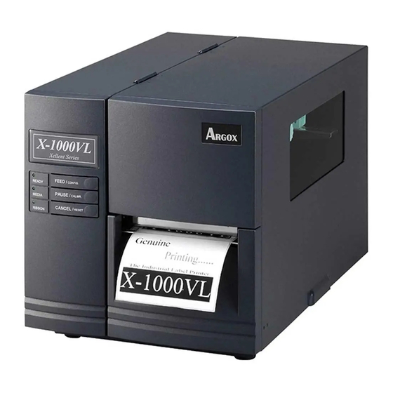
Page 3: Getting Started
1. Getting Started Example: Making a Keyboard Form Stand-alone with Barcode Reader Example: Making a Barcode Reader Form Congratulations on choosing the Argox Xellent Series (X-Series) 6. Technical Reference industrial barcode printer. This user’s manual describing the General Specifications Xellent Series printer models, will help you get to know your new Printer Programming Language A, PPLA printer. - Page 4 possible damage. 2. Open the top cover of the printer to see if the media Printer compartments are in order. Note: If damage has occurred, contact your shipping company Quick immediately to file a claim. Guide 3. Check whether you have received the following accessories together with the printer.
-
Page 5: Connecting The Power Cord
Connect the power cord as below. Connecting the Power Cord Before setting up and connecting the printer you should consider the following. WARNING! Do not operate the printer in an area where it might get wet. Find a solid flat surface with adequate room for the printer and enough space above for media and ribbon access. -
Page 6: Internal Parts And Features
Internal Parts and Features Thermal Print Head Head Latch Ribbon Supply Spindle Ribbon Pick-up Spindle Media Supply Spindle Feed Slot Bracket Paper Sensor Guide Thermal Print Head Paper Roller Standard Mode... -
Page 7: Loading Ribbon
Loading Ribbon Note: Thermal Transfer printing requires media to print with appropriate ribbon. This section can be referred to, for X-Series to use transfer thermal printing. The sample steps below are based on ribbon wound ink-side in as an example.(X series printers use ribbon wound ink-side in as default. - Page 8 4. Lead the ribbon through the print head module. (Figure 4) 5. Attach the edge of the ribbon onto the bare core and wind it a bit onto the core. Make sure the coating side of the ribbon is face down. Head Latch Bracket...
-
Page 9: Switching Ribbon Wound Ink-Side In Or Ink-Side Out
6. Insert the core onto the ribbon pick-up spindle. (Figure 5) Switching Ribbon Wound Ink-side in or Ink-side out The printer is produced to suit flexible applications, no matter with ribbon wound ink-side in (manufacturing default), or with ribbon wound ink-side out. The steps to switch for ribbon wound ink-side out are listed as follows: Pull and move the SHAFT RIBBON ADJ to “Outside”: Ribbon... -
Page 10: Loading Media
2. After the adjustment above, ribbon wound ink-side out can be Loading Media used. Then install the ribbon: The X-Series printers offer three different loading modes: standard, peel-off, or with a cutter. Standard mode allows you to collect each label freely. ... -
Page 11: Standard Mode Loading Me7Dia
Standard Mode Loading Media 2. Turn the head latch counter-clockwise and open the bracket. Remove the outside media guide. (Figure 2) 1. Insert the media roll into the media supply spindle and move the media guide to the inside. (Figure 1) Media Guide Head... - Page 12 5. Close the top cover and the front access door and turn on the printer, or press the “FEED” button if the printer is Print Head already on. (Figure 5) Module Paper Sensor Paper Sensor Guide Position Lever 4. Return the outside media guide, close the bracket, and hook the head latch.
-
Page 13: Peel Off Mode Loading Media
2. Lead the media backing paper through the print head Peel Off Mode Loading Media module. (Figure 2) Follow steps 1 to 3 in “Standard Mode Loading Media” above. 1. From the leading end of the media roll remove enough labels to expose 6-inches of backing paper. - Page 14 4. Close the peeler module using the peel-off mechanism release lever. (Figure 4) Notes: 1. The FEED button does not make the printer peel. To enable Peeling function, set by the LCD panel. 2. Make sure the peeler sensor is out of the ribbon path when installed.
-
Page 15: Cutter Mode Loading Media
2. Return the outside media guide, close the bracket, and Cutter Mode Loading Media hook the head latch. (Figure 2) Follow steps 1 to 3 in “Standard Mode Loading Media” above. 1. Insert the media into the print head module and under the paper sensor guide. -
Page 16: Adjust Position Of Label Sensor
3. Close the top access door and turn on the printer or press Adjust Position of Label Sensor the FEED button if the printer is already on. The printer will Function of the label sensor is to detect the gap, notch, or holes of then feed the labels through the cutter automatically. -
Page 17: Printer Operation
2. Printer Operation The front panel includes: 3 LED indicators (READY, MEDIA and RIBBON) The illustrations below describe parts and features of X-Series. 3 buttons (FEED, PAUSE and CANCEL) LCD display (except X-1000VL) Front Panel Top Access Door ... -
Page 18: Buttons
LCD Display direct thermal can be set via the printer panel. For the X-1000VL model, set via Printer Utility, The X-2000V / X-2000V Zip / X-2300E / X-2300ZE / X-3200 / Windows driver or printer commands. X-3200Z / X-3200E / X-3200ZE models have a LCD that shows: Buttons ... -
Page 19: Setting Display Language
Setting Display Language If a keyboard is plugged in, the LCD display will indicate: X-2000V / X-2000V Zip / X-2300E / X-2300ZE The printer’s LCD display supports six languages: English, French, German, Italian, Spanish, and Portuguese. READY (203,PPLB) Item Range Factory Default <ESC>... -
Page 20: Changing Settings From The Panel
Changing Settings from the Panel LCD Function Setting Procedure You may change settings using the buttons on the front panel of The following procedure is an example of setting procedure the X-2000V, X-2000V Zip, X-2300E, X-2300ZE, X-3200, to direct thermal printing mode: X-3200Z, X-3200E, and X-3200ZE printer models, in addition to LCD indicating LCD setting steps... - Page 21 ALTERNATIVE 3 Item Range Factory Remarks CUT PEEL -15 ~ 50 mm 0 mm To adjust cut and peel Default OFFSET positions. PRINT MODE DIRECT THERM. PRINT -8 ~ 15 mm 0 mm Controls vertical print THERMAL/ TRANSFER OFFSET positions. Positive THERM.
- Page 22 CUTTER INSTALLED DISTANCE setting. CUTTER W/O is set to “YES”. BACK BACK 10~40 mm 21 mm Available only when DISTANCE BACK FEED is PEELER enabled. INSTALLED BASE 0~99 (PPLA) Available only in READER Available only in DARKNESS PPLA and PPLB INSTALLED -28~28 (PPLB) PPLB printer...
- Page 23 SETTING COMMAND/ COMMAND Choosing priority of change contents. PRIORITY LCD settings. LCD PANEL (ex. from 000.000.000.000 to 255.255.255.255) PAUSE/CALIBR. : Ethernet settings and parameters (X-2300E. X-2300ZE. X-3200E. X-3200ZE): shift “_”sign position. Item Range Factory Remarks (ex. from 255.255.255.255 to 255.255.255.255) Default CANCEL/RESET.: DHCP...
-
Page 24: Media Calibration
Printing a Configuration Report To perform a self-test and print a configuration report, helping to Media Calibration check printer’s print quality and internal settings. Steps as below: After the media is loaded, please perform media calibration to 1. Turn off the printer. calibrate the label sensor in advance. - Page 25 1. Firmware Version Information Sample of Configuration Report – based on X-2300E: 2. Standard RAM Size 3. Available RAM Size 4. Flash Type 5. Available Flash Size 6. Font Symbol Set 7. Print Mode (Thermal Transfer or Direct Thermal) 8. Sensor type (See-Through or Reflective) 9.
-
Page 26: Resetting To Factory Default Settings
32. Mac Address Resetting to Factory Default Settings 33. SNMP To reset the printer to factory default settings: 34. DIP switch 1. Turn off the printer. Switch 2. Press and hold the CANCEL button and turn on the Direct printer. Default Thermal 3. -
Page 27: Computer Connections
3. Computer Connections Serial (RS-232) Port The required cable must have a nine-pin "D" type male connector This printer comes with USB interface, a standard Centronics on one end, which is plugged into serial port located on the back parallel interface, and a nine-pin Electronics Industries of the printer. -
Page 28: Ethernet 10/100 Internal Printer Server Option
Ethernet 10/100 Internal Printer Server Option Ethernet indication: X-2300E / X-2300ZE / X-3200E / X-3200ZE models provide Green LED Ethernet interface (RJ45), which allows host in a local area Ethernet Amber LED network to conveniently use several printers by Ethernet connectivity at the same time. -
Page 29: Communicating With The Printer
Communicating with the Printer 1. Turn off the printer. Plug the power cable into the power socket on the wall, and then connect the other end of the The bundled printer driver can be applied to all applications under cable to printer's power socket. Connect the USB cable to the Windows XP/ Vista/ Windows 7, supporting 32-bit/ 64-bit USB port on the printer and on the PC. - Page 30 4. Choose Industrial Barcode Printers on the screen, go to Instead of the flash prompt above, another way to install X-3200 product page, click on version of Seagull driver and Seagull driver is to run the DriverWizard utility from the then start installation: Installation Directory where the Seagull driver files locates.
- Page 31 6. Enter Printer name (i.e. Argox X-3200 PPLB) and select "do 8. After the related files have been copied to your system, click not share this printer”, and click "Next" "Finish". 9. After driver installation is complete, click "Close". The driver should now be installed. 7.
-
Page 32: Installing A Printer Driver (For Other Interfaces Except Usb)
Installing a Printer Driver (for other interfaces 3. Choose Industrial Barcode Printers on the screen, go to X-3200 product page, click on version of Seagull driver and except USB) then start installation: 1. Turn off the printer. Plug the power cable into the power socket on the wall, and then connect the other end of the cable to printer's power socket. - Page 33 Instead of the flash prompt above, another way to install 6. Click "Finish". Seagull driver is to run the DriverWizard utility from the Installation Directory where the Seagull driver files locates. 4. On the prompt, Windows Printer Driver, select “I accept…” and click "Next".
- Page 34 10. Enter Printer name (i.e. Argox X-3200 PPLB) and select "do not share this printer”, and click "Next". 9. Select the port of the printer and click "Next". 11. Check all the data on the showing screen, if it is correct, click Argox X-1000VL PPLB "Finish".
-
Page 35: Troubleshooting
4. Troubleshooting 12. After the related files have been copied to your system, click "Finish". Normally, if the printer is in not working properly, the "READY" LED blinks continuously, and printing and communication between the host and printer stops. LED and LCD Diagnosis Blinking LEDs indicate a problem. -
Page 36: Ribbon Problems
Ribbon Problems Cutter failed Check the media. Check the connection LED/LCD Indication between cutter and main READY and RIBBON LEDs Blinking board. LCD Display RIBBON OUT Call for service. Memory full Check graphics and soft Need to reboot the fonts from host. -
Page 37: Transmission Problems
MEMORY FULL READY Printer buffer full due to loaded soft fonts, Printer Maintenance graphics or forms. Check data format. Call for service. Vertical streaks in the printout usually indicate a dirty or faulty SENSOR O.R. READY Media calibration is out of range for sensor print head. -
Page 38: Cleaning The Print Head
from any possible damage, please use soft cloth/ cotton buds with “Ethanol” or “IPA” to clean print head surface. Cleaning the Print Head It’s strongly recommended to wear hand gloves during cleaning progress. To keep the Print Head remain in the best conditions and Do not touch print head surface by bare hands or with any hard efficiency and to extend duration for use, regular cleaning action equipment. -
Page 39: Advanced Installation And Adjustment
5. Advanced Installation and Adjustment moistened with a mild detergent. Every time a media roll is printed, you should clean this compartment to reduce the incidence dust. This chapter describes installation and adjustment procedure for X series industrial printers. It’s recommended to be carried out by technicians, in order to keep overall printing performance. -
Page 40: Left Hand Side Enhancement
Figure 1 Figure 2 Figure 3 Figure 4 Once the desired quality has been reached, please make note on the new setting of the Fine Adjustment Knob and the type number B. Left Hand Side Enhancement of ribbon been used in this printing task for future reference. If the phenomena as shown in Fig. -
Page 41: Print Head Print Line Position
Figure 1 Print Head Print Line Position When the label only exhibits locally inferior printing quality and the ribbon is not wrinkled, the position of the print head shall be adjusted, and the adjusting position is shown as Fig. 1. The viewing direction is facing the machine, and using hex socket screw driver for the adjustment. -
Page 42: Ribbon Tension Adjustment
Figure 2 Figure 3 Ribbon Tension Adjustment Both ribbon supply spindle and ribbon pickup spindle are equipped with control knobs to adjust ribbon tension. The control knobs can rotate to both directions. Rotate the control knob clockwise to increase ribbon tension; rotate it counter-clockwise to reduce ribbon tension. -
Page 43: Printing Wrinkle
setting when shipped from Argox factory is shown as Figure 2 – the two arrows are in line with the black line. Printing Wrinkle Figure 1 During printing, ribbon may wrinkle and cause abnormal printing quality. The following describes how to solve ribbon wrinkle accordingly. - Page 44 4. If the test print appears as Figure A, remain the screw at the right of Ribbon Bracket fixed, then loose the screw at the left, and gradually fine-tune upward, until the print quality gets improved. If the test print appears as Figure B, remain the screw at the left of Ribbon Bracket fixed, and then loose the screw at the right, and gradually fine-tune upward, until the print quality gets improved.
-
Page 45: Rotary Cutter And Guillotine Cutter Installation
5. Insert the left side of cutter bracket (7) and secure the two Rotary Cutter and Guillotine Cutter Installation screws (6) to the print module. Refer to the following steps to install the cutter kit onto printers: Rotary Cutter 1. Turn off the printer. 2. -
Page 46: Rotary Cutter And Guillotine Cutter Settings
6. Thread the cutter cable through hole (8) and route it to the JP16 connector (CUTTER) on the X-1000VL/ X-2000V/ Rotary Cutter and Guillotine Cutter Settings X-2000V Zip main boards, or to the JP14 connector Before printing and cutting tasks, please make sure whether the (CUTTER) on the main board of X-3200/ X-3200Z/ cutter in use is Rotary Cutter, or Guillotine Cutter. - Page 47 3. “Cutter Setup” prompts will be indicated as below. Check on the radio button, “Rotary” if there’s Rotary Cutter 4. Go to “Printing Preference” prompt of CP-2140 driver and then installed. click on the “Stock” tag. Check “Post-Print Action” settings and Then click “OK“: select “Cut”.
-
Page 48: Rotary Cutter With Paper Jam
Guillotine Cutter with Paper Jam Rotary Cutter with Paper Jam If there is paper jam inside guillotine cutter, check in Figure 1 and find where the screw under guillotine cutter. It is to control cut If there is paper jam inside rotary cutter, refer to Rotary Cutter Installation section to remove the rotary cutter. -
Page 49: Dispenser Installation
Dispenser Installation Connect the Peeler sensor to main board JP15 socket of X-1000VL, X-2000V, X-2000V Zip / JP12 socket of Install a dispenser into the printer as follows: X-3200, X-3200Z, X-3200E, X-3200ZE, X-2300E, and X-2300ZE. Secure the dispenser board onto printer case. -
Page 50: Rtc Battery Replacement
For the X-1000VL, ignore this step. RTC Battery Replacement 1. Turn off the printer; disconnect the AC power cable. 2. Open the left cover of printer. 3. Loose the lock for RTC Battery on main board and then replace with a known good RTC battery. Install the ribbon and media. -
Page 51: Stand-Alone With Keyboard
Stand-alone with Keyboard Form Control Functions This section covers stand-alone operation with keyboard. It is Function applicable with printer models: Enter or exit from keyboard mode PS/2 Argokee Backspace Delete the last typed character Keyboard Printer Next form if more than one form exists PPLA PPLB Basic... -
Page 52: Example: Making A Keyboard Form
3. Turn off the printer, connect the keyboard and then turn on Example: Making a Keyboard Form the printer. The LCD displays this message: 1. Make a command file for the form, KBD.FRM. READY (203,PPLB) Command Description <ESC> FOR KEYBD Enable store to flash FK"KBDFORM"... - Page 53 7. Press <ENTER> to continue to the next label and repeat steps 5 ~ 7, or <ESC> to exit. ENTER to go on, Or ESC to return 8. Output:...
-
Page 54: Stand-Alone With Barcode Reader
Stand-alone with Barcode Reader Example: Making a Barcode Reader Form This section covers stand-alone operation with barcode readers. It is applicable with printer models: 1. Make a command file for a form, READER.FRM. Barcode Reader Interface PS/2 RS-232 Command Description Printer PPLB PPLB... - Page 55 2. Send the file READER.FRM to printer under MS-DOS >COPY/B READER.FRM LPT1: 3. Turn off the printer, connect the barcode reader, turn on the printer and set “Reader installed” on the LCD to ON position. 4. The form READER is automatically executed. Scan product name and number from printed bar codes using the barcode reader.
-
Page 56: Technical Reference
6. Technical Reference Reflective & See-through media sensors (movable) Sensors Head open switch General Specifications Ribbon end sensor X-2300E X-3200 indicator LED indicator x 3, Button x 3, X-2000V X-3200E X-1000 X-2300Z X-3200 x 3, X-2000V Display Back-lit LCD Display 16 x 2-line X-3200ZE Button x Multilingual... - Page 57 Guillotine Cutter Wax, Wax/Resin, Resin Ribbon Rotary Cutter (ribbon wound ink-side out or ink-side in available) Guillotine Cutter Dispenser Rotary Cutter Ribbon width: 1”~4” (25.4 mm~101.6 mm) Rewinder Options Media Stacker Dispenser Ribbon Length: max 360m Wax, 300m Semi-Resin Ribbon Size Rewinder Ribbon roll max OD 3”...
-
Page 58: Printer Programming Language A, Ppla
HIBC Fonts, Bar Codes and Graphics Specification Codabar Plessey The specifications of fonts, bar codes and graphics depends on UPC2 the printer emulation. The emulation is a printer programming UPC5 language through which the host can communicate with your Code 93 printer. -
Page 59: Printer Programming Language Z, Pplz
MaxiCode Font Expandability 1x1 to 24x24 2D Bar Code PDF417 Types Character Rotation 0, 90, 180, 270 degree, 4 direction rotation Data Matrix (ECC 200 only) QR code Soft Fonts True Type fonts can be downloaded by Font Composite Codes Utility (Two-byte Asian fonts also can be Graphics... -
Page 60: Interface Specifications
Interface Specifications EAN-8 Codabar EAN-13 This section presents the interface specifications of IO ports for Plessey the printer. These include pin assignments, protocols and detailed GS1 Data bar (RSS) information about how to properly interface your printer with your 2D Bar Code MaxiCode host or terminal. -
Page 61: Serial Interface
Connection with Host: Serial Interface Host 25S Printer 9P Host 9S Printer 9P The RS-232 connector on the printer side is a female, DB-9. (PC or compatible) (PC or compatible) DTR 20 …… 1 DSR DTR 4 …… 1 DSR DSR 6 ……... -
Page 62: Parallel (Centronics)
The simplest way to connect to other hosts (not PC compatible) or terminals is: Parallel (Centronics) The parallel port is a standard 36-pin Centronics connector. Pin Printer Terminal/Host assignments are as follows: Pin 2- RxData ……… TxData Pin 3- TxData ……… RxData Pin Direction Definition... -
Page 63: Ethernet Interface
Ethernet Interface The following port complies with Ethernet communication. ASCII TABLE " Signal XOFF Transmit+ Transmit- Receive+ & Reserved ‛ Reserved Receive- Reserved Reserved Auto Polling < Both the serial port and parallel port of this printer can be active at the same time, i.e.