Argox X-3200ZE User Manual
Hide thumbs
Also See for X-3200ZE:
- User manual (63 pages) ,
- User manual (120 pages) ,
- User manual (124 pages)

Related Manuals for Argox X-3200ZE


Summary of Contents for Argox X-3200ZE
- Page 1 X-1000VL / X-2000V / X-2000V Zip X-2300 / X-2300Z X-2300E / X-2300ZE X-3200 / X-3200Z X-3200E / X-3200ZE Xellent Series Industrial Barcode Printer User’s Manual Argox website: http://www.argox.com...
-
Page 2: Table Of Contents
Table of Contents 1. Getting Started Unpacking Connecting the Power Cord Internal Parts and Features Loading Ribbon Switching Ribbon Wound Ink-side in or Ink-side out Loading Media Standard Mode Loading Media Peel Off Mode Loading Media Cutter Mode Loading Media Adjust Position of Label Sensor 2. - Page 3 Installing a Printer Driver (for other interfaces except USB) 4. Troubleshooting LED and LCD Diagnosis Media Problems Ribbon Problems Other Problems Printer Status Transmission Problems Recovery Printer Maintenance Cleaning the Print Head Cleaning Interval Cleaning Material Cleaning Direction Cleaning the Roller Cleaning the Media Compartment 5.
- Page 4 6. Technical Reference General Specifications Printer Programming Language A, PPLA Printer Programming Language B, PPLB Printer Programming Language Z, PPLZ Interface Specifications PS/2 Serial Interface Connection with Host: Parallel (Centronics) Ethernet Interface Auto Polling ASCII TABLE...
-
Page 5: Getting Started
1. Getting Started Congratulations on choosing the Argox Xellent Series (X-Series) industrial barcode printer. This user’s manual describing the Xellent Series printer models, will help you get to know your new printer. The manual includes a guide to operate the printer as well as related information on troubleshooting, maintenance, and technical reference. - Page 6 possible damage. 2. Open the top cover of the printer to see if the media compartments are in order. Note: If damage has occurred, contact your shipping company immediately to file a claim. 3. Check whether you have received the following accessories together with the printer.
-
Page 7: Package Contents
Printer Quick Guide Power Cord USB Cable 1” ID Core for Ribbon Package Contents Printer Power Cord Quick Guide Core for Ribbon USB Cable ... -
Page 8: Connecting The Power Cord
Connecting the Power Cord Before setting up and connecting the printer you should consider the following. WARNING! Do not operate the printer in an area where it might get wet. Find a solid flat surface with adequate room for the printer and enough space above for media and ribbon access. - Page 9 Connect the power cord as below.
-
Page 10: Internal Parts And Features
Internal Parts and Features Ribbon Supply Spindle Ribbon Pick-up Spindle Media Supply Spindle Feed Slot Bracket Thermal Print Head... - Page 11 Thermal Print Head Head Latch Paper Sensor Guide Paper Roller Standard Mode...
- Page 12 Peel Off Mode Cutter Mode...
-
Page 13: Loading Ribbon
Loading Ribbon Note: Thermal Transfer printing requires media to print with appropriate ribbon. This section can be referred to, for X-Series to use transfer thermal printing. The sample steps below are based on ribbon wound ink-side in as an example. (X series printers use ribbon wound ink-side in as default. - Page 14 Head Latch Bracket 3. Unwrap the ribbon and separate the ribbon roll from the bare core. Insert the ribbon roll onto the ribbon supply spindle. (Figure 3) Ribbon Supply Spindle...
- Page 15 4. Lead the ribbon through the print head module. (Figure 4) 5. Attach the edge of the ribbon onto the bare core and wind it a bit onto the core. Make sure the coating side of the ribbon is face down. Print Head Bare Core...
- Page 16 6. Insert the core onto the ribbon pick-up spindle. (Figure 5) Ribbon Ribbon Pick-up Pick-up Spindle Spindle 7. Turn the pick-up spindle to ensure the ribbon is tightly wound.
-
Page 17: Switching Ribbon Wound Ink-Side In Or Ink-Side Out
Switching Ribbon Wound Ink-side in or Ink-side out The printer is produced to suit flexible applications, no matter with ribbon wound ink-side in (manufacturing default), or with ribbon wound ink-side out. The steps to switch for ribbon wound ink-side out are listed as follows: Pull and move the SHAFT RIBBON ADJ to “Outside”:... - Page 18 2. After the adjustment above, ribbon wound ink-side out can be used. Then install the ribbon: 3. If ribbon wound ink-side in is in use, pull and move the SHAFT RIBBON ADJ to “Inside”. Then install the ribbon:...
-
Page 19: Loading Media
Loading Media The X-Series printers offer three different loading modes: standard, peel-off, or with a cutter. Standard mode allows you to collect each label freely. Peel-off mode peels backing material away from the label as it prints. After the label is removed, the next label prints. Cutter mode automatically cuts the label after it prints. -
Page 20: Standard Mode Loading Media
Standard Mode Loading Media 1. Insert the media roll into the media supply spindle and move the media guide to the inside. (Figure 1) Media Guide Media Supply Spindle... - Page 21 2. Turn the head latch counter-clockwise and open the bracket. Remove the outside media guide. (Figure 2) Head Latch Outside Media Guide Bracket 3. Lead the media through the print head module and under the paper sensor guide. (Figure 3)
- Page 22 Print Head Module Paper Sensor Paper Sensor Guide Position Lever Module 4. Return the outside media guide, close the bracket, and hook the head latch. (Figure 4) Head Latch Bracket Outside Media Guide...
- Page 23 5. Close the top cover and the front access door and turn on the printer, or press the “FEED” button if the printer is already on. (Figure 5)
-
Page 24: Peel Off Mode Loading Media
Peel Off Mode Loading Media Follow steps 1 to 3 in “Standard Mode Loading Media” above. 1. From the leading end of the media roll remove enough labels to expose 6-inches of backing paper. (Figure 1) Backing Paper... - Page 25 2. Lead the media backing paper through the print head module. (Figure 2) Print Head Module 3. Push down the peel-off mechanism release lever and lead the media under the peeler module. (Figure 3) Dispenser Module Peel Lever...
- Page 26 4. Close the peeler module using the peel-off mechanism release lever. (Figure 4) Peel Lever Dispenser Module 5. Close the top access door and turn on the printer or press the FEED button if the printer is already on. (Figure 5)
- Page 27 Notes: 1. The FEED button does not make the printer peel. To enable Peeling function, set by the LCD panel. 2. Make sure the peeler sensor is out of the ribbon path when installed.
-
Page 28: Cutter Mode Loading Media
Cutter Mode Loading Media Follow steps 1 to 3 in “Standard Mode Loading Media” above. 1. Insert the media into the print head module and under the paper sensor guide. (Figure 1) Print Head Module Paper Sensor Guide... - Page 29 2. Return the outside media guide, close the bracket, and hook the head latch. (Figure 2) Head Latch Outside Media Bracket Guide...
- Page 30 3. Close the top access door and turn on the printer or press the FEED button if the printer is already on. The printer will then feed the labels through the cutter automatically. (Figure Cutter Note: The FEED button does not make the printer cut. To enable Cutter function, set by the LCD panel...
-
Page 31: Adjust Position Of Label Sensor
Adjust Position of Label Sensor Function of the label sensor is to detect the gap, notch, or holes of labels, to help the printer for accurate print positions and label length. For labels with gaps, label sensor can be positioned wherever media locates. -
Page 32: Printer Operation
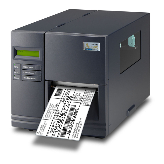
2. Printer Operation The illustrations below describe parts and features of X-Series. Front Panel X-1000VL LEDs and Buttons Top Access Door Front Access Door X-2000V LCD Display X-2000V Zip X-2300 X-2300Z X-2300E X-2300ZE X-3200 X-3200Z X-3200E X-3200ZE... -
Page 33: Led Indicators
Off – direct thermal mode with no ribbon installed. Blinking – Ribbon is used out; install new ribbon. For the X-2000V / X-2000V Zip / X-2300 / X-2300Z / X-2300E / X-2300ZE / X-3200 / X-3200Z / X-3200E / X-3200ZE models, modes of thermal transfer and... -
Page 34: Buttons
direct thermal can be set via the printer panel. For the X-1000VL model, set via Printer Utility, Windows driver or printer commands. Buttons There are three buttons, each with two basic functions. Button Function 1 Function 2 (Press the button and (Press the button) power switch together) FEED... -
Page 35: Lcd Display
X-2000V/ X-2000V Zip/ X-2300/ X-2300Z/ X-2300E/ X-2300ZE READY (203,PPLB) X-3200 / X-3200Z / X-3200E / X-3200ZE READY (300,PPLB) The first parameter is either 203 or 300, which stands for the printer resolution. The second parameter indicates the emulation (printer language), PPLA, PPLB or PPLZ. - Page 36 If a keyboard is plugged in, the LCD display will indicate: X-2000V/ X-2000V Zip/ X-2300/ X-2300Z/ X-2300E/ X-2300ZE READY (203,PPLB) <ESC> FOR KEYBD X-3200 / X-3200Z / X-3200E / X-3200ZE READY (300,PPLB) <ESC> FOR KEYBD If a barcode reader is connected, the LCD display will indicate:...
-
Page 37: Setting Display Language
Setting Display Language The printer’s LCD display supports six languages: English, French, German, Italian, Spanish, and Portuguese. Item Range Factory Default LANGUAGE ENGLISH, ENGLISH FRENCH, GERMAN, ITALIAN, SPANISH, PORTUGUESE, SIMPLIFIED CHINESE To select a language: 1. Press the PAUSE and CANCEL buttons at the same time. 2. -
Page 38: Changing Settings From The Panel
You may change settings using the buttons on the front panel of the X-2000V, X-2000V Zip, X-2300, X-2300Z, X-2300E, X-2300ZE, X-3200, X-3200Z, X-3200E, and X-3200ZE printer models, in addition to changing settings via software commands. Change settings via buttons on panel:... - Page 39 LCD Function Setting Procedure The following procedure is an example of setting procedure to direct thermal printing mode: LCD indicating LCD setting steps After printer power in on, LCD will indicate READY (203,PPLB) as shown at the left. Step 1 Press both PAUSE + CANCEL buttons.
- Page 40 Item Range Factory Remarks Default PRINT MODE DIRECT THERM. THERMAL/ TRANSFER THERM. TRANSFER AUTO-CAL. MODE 1 MODE 1 Mode 1: Printer MODE performs Auto MODE 2 Calibration after MODE 3 printing the first label, MODE 4 if label height differs from parameters in printer's flash.
- Page 41 ALTERNATIVE ALTERNATIVE CUT PEEL -15 ~ 50 mm 0 mm To adjust cut and peel OFFSET positions. PRINT OFFSET -8 ~ 15 mm 0 mm Controls vertical print positions. Positive value only. For X-2000V only. TPH VER -9~9 mm 0 mm To adjust offset of OFFSET vertical print position.
- Page 42 PART CUT MODE NORMAL NORMAL Available only when CUTTER INSTALLED CUTTER W/O is set to “YES”. BACK PEELER INSTALLED READER Available only in INSTALLED PPLB printer language. WIN. CON. LEN. 0 ~ 254 mm 0 mm Available only in Windows with bundled printer driver and for continuous media.
- Page 43 selected, printer enters BACK DISTANCE setting. BACK 10~40 mm 21 mm Available only when DISTANCE BACK FEED is enabled. BASE 0~99 (PPLA) Available only in DARKNESS PPLA and PPLB -28~28 (PPLB) printer languages. ABS. 0~30 To select darkness. DARKNESS Available only in PPLZ printer language.
- Page 44 PRIORITY LCD settings. It LCD PANEL decides which setting method - by command or by LCD panel, is prior. Ethernet settings and parameters (X-2300E. X-2300ZE. X-3200E. X-3200ZE): Item Range Factory Remarks Default DHCP DISABLE If printer has been connected to a...
- Page 45 MASK When DHCP is disabled, default IP address is 192.168.1.100. xxx.xxx.xxx.xxx DEFAULT GATEWAY If “_” sign appears, that means that DHCP setting is disabled. On the contrary, DHCP setting is enabled. FEED/CONFIG. : change contents. (ex. from 000.000.000.000 to 255.255.255.255) PAUSE/CALIBR.
-
Page 46: Media Calibration
Media Calibration After the media is loaded, please perform media calibration to calibrate the label sensor in advance. 1. Turn off the printer 2. Press and hold the PAUSE button and turn on the power. 3. When “CALIBRATION …” is displayed on the LCD, and both READY and MEDIA indicators blink, release the PAUSE button. - Page 47 accuracy, especially for small labels less than 1.5” high.
-
Page 48: Printing A Configuration Report
Printing a Configuration Report To perform a self-test and print a configuration report, helping to check printer’s print quality and internal settings. Steps as below: 1. Turn off the printer. 2. Load media and ribbon. 3. Press and hold the FEED button while turning on the power. 4. - Page 49 1. Firmware Version Information 2. Standard RAM Size...
- Page 50 7. Print Mode (Thermal Transfer or Direct Thermal) 8. Sensor type (See-Through or Reflective) 9. Label-less Calibration Value 10. No. of downloaded Soft Fonts 11. RTC Time 12. No. of downloaded Argox Format Fonts 13. Cut Count 14. Print Length Meter 15. RS232 Protocols 16. Check Sum 17.
- Page 51 34. DIP switch Switch Direct Default Thermal 35. Font Image Remark: What continue after the parameters are test patterns of print head.
-
Page 52: Resetting To Factory Default Settings
Resetting to Factory Default Settings To reset the printer to factory default settings: 1. Turn off the printer. 2. Press and hold the CANCEL button and turn on the printer. For X-1000VL: When RIBBON indicator blinks, release the CANCEL button. For printer models other than X-1000VL: When “RESET …”... - Page 53 Notes: 1. For X-1000VL, the steps about LCD can be ignored. 2. Be cautioned that this will reset all printer settings back to defaults; if possible, print the configuration label in advance before reset. 3. All settings stored in FLASH memory are retained even after turning off the printer.
-
Page 54: Computer Connections
3. Computer Connections This printer comes with USB interface, a standard Centronics parallel interface, and a nine-pin Electronics Industries Association (EIA) RS-232 serial data interface. USB Interface Requirements The Universal Serial Bus (USB) interface is compatible with your existing PC hardware. The USB’s “plug and play” design makes installation easy. - Page 55 Technical Reference in this manual. Note: 1. Centronics allows a much higher communication speed than serial. 2. The pin assignment of serial cable is different from PC. Please contact your local Argox reseller if you need this cable. Centronics Parallel PS/2 Serial (RS-232)
-
Page 56: Ethernet 10/100 Internal Printer Server Option
Ethernet 10/100 Internal Printer Server Option X-2300E / X-2300ZE / X-3200E / X-3200ZE models provide Ethernet interface (RJ45), which allows host in a local area network to conveniently use several printers by Ethernet connectivity at the same time. Note: When using Ethernet model printer, please wait till the Ready Indicator to stop blinking, before starting printer operations. - Page 57 Ethernet indication: Green LED Ethernet Amber LED Centronics Parallel PS/2 Serial (RS-232) Power Switch AC Power connector...
-
Page 58: Communicating With The Printer
Windows software applications including Argox Bartender UL label editing software or MS Word, etc., to print to this printer. Drivers can be downloaded from Argox website >> Technical Support >> Download Center >> select product model to access: http://www.argox.com/content.php?sno=0000033... -
Page 59: Installing A Plug And Play Printer Driver (For Usb Only)
Windows Add Hardware Wizard will automatically detect the printer and display a dialog that allows you to install a driver. Click Cancel and do not install the driver using this wizard. 3. Run the driver from Argox website. On the prompt, Windows... - Page 60 Printer Driver, select “I accept…” and click "Next". 4. Assign the directory to keep Seagull driver, (for example: C:\Seagull) and click "Next". 5. Click "Finish".
- Page 61 6. Select Install printer drivers and Click "Next" 7. On the Seagull Driver Wizard prompt, select the first radio...
- Page 62 “Install a driver for a Plug and Play printer”. Then click “Next.” 8. Enter Printer name (i.e. Argox X-3200 PPLB) and select "do not share this printer”, and click "Next"...
- Page 63 9. Check all the data on the showing screen, if it is correct, click "Finish". 10. After the related files have been copied to your system, click "Finish". 11. After driver installation is complete, click "Close".
- Page 64 The driver should now be installed.
-
Page 65: Installing A Printer Driver (For Other Interfaces Except Usb)
Connect the Parallel cable, Serial cable, or Ethernet cable to the proper port on printer and also on your computer. 2. Run the driver from Argox website. On the prompt, Windows Printer Driver, select “I accept…”and click "Next". - Page 66 3. Assign the directory to keep Seagull driver, (for example: C:\Seagull) and click "Next". 4. Click "Finish".
- Page 67 5. Select Install printer drivers and Click "Next" 6. Make sure printer is connected to PC, select “Other” and click “Next”:...
- Page 68 7. Select model & emulation - the following examples are based on model X-3200 PPLB: 8. Select the port of the printer and click "Next".
- Page 69 9. Enter Printer name (i.e. Argox X-3200 PPLB) and select "do not share this printer”, and click "Next". 10. Check all the data on the showing screen, if it is correct, click "Finish".
- Page 70 11. After the related files have been copied to your system, click "Finish". 12. After driver installation is complete, click "Close". The driver should now be installed.
-
Page 71: Troubleshooting
4. Troubleshooting Normally, if the printer is in not working properly, the "READY" LED blinks continuously, and printing and communication between the host and printer stops. LED and LCD Diagnosis Blinking LEDs indicate a problem. Check the LEDs and the LCD display and refer to the following solutions: Media Problems LED/LCD... -
Page 72: Ribbon Problems
Ribbon Problems LED/LCD Indication READY and RIBBON LEDs Blinking LCD Display RIBBON OUT Possible Problems Solutions Remarks Ribbon out Supply the ribbon roll Not applicable to direct thermal. Ribbon jam Recover the jam Ribbon sensor error Replace ribbon sensor Note: If you use direct thermal, set with panel, Windows driver or command. -
Page 73: Printer Status
Check the media. Cutter failed Check the connection between cutter and main board. Call for service. Memory full Check graphics and soft Need to reboot the fonts from host. Delete by system. application software for those no longer in use. Note: After problem is solved, press CANCEL to continue printing. -
Page 74: Transmission Problems
graphics or forms. Check data format. Call for service. SENSOR O.R. READY Media calibration is out of range for sensor detection. Make sure media is loaded and media sensor locates under media. PRINT HEAD MEDIA Printing job will start until the temperature of TPH goes down. -
Page 75: Printer Maintenance
Printer Maintenance Vertical streaks in the printout usually indicate a dirty or faulty print head. (Refer to the following examples.) Clean the print head. If the problem persists, replace the print head. For unstable ribbon roll rotation, check the label path and make sure the head latch is securely closed. -
Page 76: Cleaning The Print Head
Cleaning the Print Head To keep the Print Head remain in the best conditions and efficiency and to extend duration for use, regular cleaning action is needed. Note: Turn off the printer before cleaning. Clean the print head as follows: 1. -
Page 77: Cleaning Direction
It’s strongly recommended to wear hand gloves during cleaning progress. Do not touch print head surface by bare hands or with any hard equipment. Water or spit should be kept away in case of corrosion on heating elements. Cleaning Direction When cleaning the print head, always wipe in One-Way Direction - from Left to Right only, or, from Right to Left only, to clean “Heating Line”... -
Page 78: Advanced Installation And Adjustment
5. Advanced Installation and Adjustment This chapter describes installation and adjustment procedure for X series industrial printers. It’s recommended to be carried out by technicians, in order to keep overall printing performance. Print Head Pressure Printing quality can be fine adjusted based on which area on the label the printing quality discrepancy is located. - Page 79 B. Left Hand Side Enhancement If the phenomena as shown in Fig. 3 been observed, please turn the Fine Adjustment Knob clockwise slightly then try printing again to justify the printing quality improvement as shown in Fig.4. Repeat the same process until the printing quality is well balanced on both ends of the label.
- Page 80 [Remark]: Please note, as shown in Fig. 2 and Fig. 4, the Fine Adjustment Knob is set to “ 0 “ as default setting when shipped from Argox factory.
-
Page 81: Print Head Print Line Position
Print Head Print Line Position When the label only exhibits locally inferior printing quality and the ribbon is not wrinkled, the position of the print head shall be adjusted, and the adjusting position is shown as Fig. 1. The viewing direction is facing the machine, and using hex socket screw driver for the adjustment. - Page 82 Figure 1...
- Page 83 Figure 2 Figure 3...
-
Page 84: Ribbon Tension Adjustment
The default setting when shipped from Argox factory is shown as Figure 2 – the two arrows are in line with the black line. - Page 85 Figure 1 Figure 2...
-
Page 86: Printing Wrinkle
Printing Wrinkle During printing, ribbon may wrinkle and cause abnormal printing quality. The following describes how to solve ribbon wrinkle accordingly. Figure A Figure B Once the printouts as above appear, the possible cause may be the unequal positions of Ribbon Bracket, which needs to be adjusted properly to make its heights equally the same at both sides. - Page 87 2. Make sure the Ribbon Bracket is at its lowest position first; then tight up the screws by rotating clockwise. 3. Print a test page to check print quality. If the quality is improved, stop the adjustment; if not, continue with next step.
- Page 88 4. If the test print appears as Figure A, remain the screw at the right of Ribbon Bracket fixed, then loose the screw at the left, and gradually fine-tune upward, until the print quality gets improved. If the test print appears as Figure B, remain the screw at the left of Ribbon Bracket fixed, and then loose the screw at the right, and gradually fine-tune upward, until the print quality gets improved.
-
Page 89: Rotary Cutter And Guillotine Cutter Installation
3. Install the Cutter Baby Board to the main board JP17 connector of X-1000VL, X-2000V, X-2000V Zip / JP15 connector of X-2300, X-2300Z, X-2300E, X-2300ZE, X-3200, X-3200Z, X-3200E, X-3200ZE. 4. Loose the three screws from Tear-off Bracket and then remove Tear Bracket. - Page 90 5. Insert the left side of cutter bracket (7) and secure the two screws (6) to the print module. Rotary Cutter Guillotine Cutter...
- Page 91 X-2000V Zip main boards, or to the JP14 connector (CUTTER) on the main board of X-2300/ X-2300Z/ X-2300E/ X-2300ZE/ X-3200/ X-3200Z/ X-3200E/ X-3200ZE. 7. Turn on the printer. 8. For the models with LCD, set the parameter of “CUTTER INSTALLED” on the LCD to the ON position. For X-1000VL model, enable cutter setting by printer driver or commands.
-
Page 92: Rotary Cutter And Guillotine Cutter Settings
Rotary Cutter and Guillotine Cutter Settings Before printing and cutting tasks, please make sure whether the cutter in use is Rotary Cutter, or Guillotine Cutter. Then select proper settings via Seagull Driver for printer. The following installation steps are based on X-3200 as an example. 1. - Page 93 3. “Cutter Setup” prompts will be indicated as below. Check on the radio button, “Rotary” if there’s Rotary Cutter installed. Then click “OK“: Check on the radio button, “Guillotine” if there’s Guillotine Cutter installed. Then click “OK“:...
- Page 94 4. Go to “Printing Preference” prompt of X-3200 driver and then click on the “Stock” tag. Check “Post-Print Action” settings and select “Cut”. ※ If there’s Guillotine Cutter installed and partial cut function is needed, select “Partial Cut” in “Post-Print Action”.
-
Page 95: Rotary Cutter With Paper Jam
Rotary Cutter with Paper Jam If there is paper jam inside rotary cutter, refer to Rotary Cutter Installation section to remove the rotary cutter. Check the Cam as screwdriver marked in Figure 1, find a slotted to turn counter-clockwise as Figure 2. During turning the Cam of cutter, release the blade from paper and them remove the paper from the cutter. -
Page 96: Guillotine Cutter With Paper Jam
Guillotine Cutter with Paper Jam If there is paper jam inside guillotine cutter, check in Figure 1 and find where the screw under guillotine cutter. It is to control cut Phillips screwdriver actions of guillotine cutter. Find a to lay down the blade by turning the screw counter-clockwise. -
Page 97: Dispenser & Rewinder Installation
3. Assemble the related components for both left and right sides. Check below: Thread the dispenser cable through a hole and route it to main board JP15 connector (PEELER) of X-1000VL, X-2000V, X-2000V Zip / JP12 connector (PEELER) of X-2300, X-2300Z, X-2300E, X-2300ZE, X-3200, X-3200Z, X-3200E, X-3200ZE. - Page 98 5. Insert the left side of dispenser bracket and secure the three screws to the print module.
- Page 99 6. Install the ribbon and media. 7. Turn on the printer. 8. For the models with LCD, set the parameter of “DISPENSER INSTALLED” on the LCD to the ON position. For X-1000VL model, enable dispenser setting by printer driver or commands.
-
Page 100: Rtc Battery Replacement
RTC Battery Replacement RTC stands for real-time clock. It is a battery powered clock that keep track of the current date and time. If your printer has a built-in RTC, you’ll find the RTC battery on the main board. The RTC battery keeps the RTC running even if the printer is turned off. -
Page 101: Stand-Alone With Keyboard
Stand-alone with Keyboard This section covers stand-alone operation with keyboard. It is applicable with printer models: PS/2 Argokee Keyboard Printer PPLA PPLB Basic PPLB only Language X-1000VL X-1000VL X-2000V X-2000V X-2000V X-2300 X-2300 X-2300 Model X-2300Z X-2300Z X-3200 models X-3200 X-3200 X-2300E X-2300E... - Page 102 Form Control Functions: Function Enter or exit from keyboard mode Backspace Delete the last typed character Next form if more than one form exists Enter - Select the form - End of typed data...
- Page 103 Example: Making a Keyboard Form 1. Make a command file for the form, KBD.FRM. Command Description Enable store to flash FK"KBDFORM" Delete previous one FS"KBDFORM" Start of form V00,15,N,"Product Name ?" Variable and display message C0,10,N,+1,"Product No. ?" Counter and display message Q50,24 Label dimension q816...
- Page 104 3. Turn off the printer, connect the keyboard and then turn on the printer. The LCD displays this message: READY (203,PPLB) <ESC> FOR KEYBD 4. Press <ESC> to enter the keyboard mode and the form name appears. Press <ENTER> to select the form. KBDFORM ...
- Page 105 7. Press <ENTER> to continue to the next label and repeat steps 5 ~ 7, or <ESC> to exit. ENTER to go on, Or ESC to return 8. Output:...
-
Page 107: Stand-Alone With Barcode Reader
Stand-alone with Barcode Reader This section covers stand-alone operation with barcode readers. It is applicable with printer models: Barcode Reader Interface PS/2 RS-232 Printer PPLB PPLB Language X-2000V X-2300 Model X-3200 X-1000VL X-2300E X-3200E To use the printer in stand-alone operation with a barcode reader (scanner), follow the procedure described below 1. - Page 108 Example: Making a Barcode Reader Form 1. Make a command file for a form, READER.FRM. Command Description Enable store to flash FK"READER" Delete previous one FS"READER" Start of form V00,15,N,"Product Name ?" Variable and display message C0,10,N,+1,"Product No. ?" Counter and display message Q50,24 Label dimension q816...
- Page 109 2. Send the file READER.FRM to printer under MS-DOS >COPY/B READER.FRM LPT1: 3. Turn off the printer, connect the barcode reader, turn on the printer and set “Reader installed” on the LCD to ON position. 4. The form READER is automatically executed. Scan product name and number from printed bar codes using the barcode reader.
- Page 110 Notes: 1. To return to normal operation, press and hold the CANCEL button and turn on the printer again. 2. When using a keyboard or barcode reader communicating with a host through the Centronics or serial port is prohibited. 3. For the keyboard form the P command is not allowed, while for the barcode reader/scanner form a PA command must be included.
-
Page 111: Technical Reference
6. Technical Reference General Specifications X-2300 X-3200 X-1000VL X-2000V X-2300E X-3200E Printing Direct Thermal and Thermal Transfer Method 203 dpi 300 dpi Printing Resolution (8 dots/mm) (12dots/mm) Printing Max 4.09” (104mm) Max 4.16” (105.7mm) Width Max. 100” Max. 50” Max. 50” (2540 mm) Printing (1270 mm) - Page 112 (baud rate PS/2 interface, interfaces to 115200 Ethernet 10/100MB (X-2300E / X-2300ZE / bps), X-3200E / X-3200ZE) Media Roll-feed, die-cut, continuous, fan-fold, tags, ticket in thermal Types paper or plain paper, fabric labels Max. media width: 4.4” (112mm) Min. media width: 1” (25.4 mm) Maximum Media thickness: 0.0025”~0.01”(0.0635mm~0.254mm)
- Page 113 Operating Win XP/ Vista/ Windows 7/ Windows 8 Systems X-1000VL, X-2000V, X-2300, X-2300E, X-3200, X-3200E: Printer PPLA, PPLB Languages X-2000V Zip, X-2300Z, X-2300ZE, X-3200Z, X-3200ZE: PPLZ Standard Real Time Clock (Battery for RTC: (RTC) Type CR2032, +3V, 225mAh) Guillotine Cutter...
- Page 114 Agency CE, cULus, FCC class A, CCC, S-Mark, RoHS Listing Note: 1. Since Font Card and optional RTC Card share the same slot on X-1000VL and X-2000V, they cannot be used at the same time. 2. The X Series models, except X-1000VL, can connect to PC keyboard via PS/2 port for standalone operation.
-
Page 115: Printer Programming Language A, Ppla
Fonts, Bar Codes and Graphics Specification The specifications of fonts, bar codes and graphics depends on the printer emulation. The emulation is a printer programming language through which the host can communicate with your printer. There are three printer programming languages, PPLA, PPLB and PPLZ. Printer Programming Language A, PPLA X-1000VL / X-2000V / X-2300 / Specification... -
Page 116: Printer Programming Language B, Pplb
Code 93 Postnet UCC/EAN-128 UCC/EAN-128 K-MART UCC/EAN-128 Random Weight Telepen Interleave 2 of 5 (Standard/with modulo 10 checksum/with human readable check digit/with modulo 10 checksum & shipping bearer bars) GS1 Data bar (RSS) MaxiCode PDF417 Data Matrix (ECC 200 only) 2D Bar Code QR code Types... - Page 117 Character Rotation 0, 90, 180, 270 degree, 4 direction rotation True Type fonts can be downloaded by Font Utility Soft Fonts (Two-byte Asian fonts also can be downloaded to X-2300 / X-3200 / X-2300E / X-3200E) Code 39 UPC-A UPC-E Matrix 2 of 5 UPC-Interleaved 2 of 5 Code 39 with check sum digit...
-
Page 118: Printer Programming Language Z, Pplz
Character Rotation 0, 90, 180, 270 degree, 4 direction rotation True Type fonts can be downloaded by Font Utility Soft Fonts (Two-byte Asian fonts also can be downloaded to X-2300Z / X-3200Z / X-2300ZE / X-3200ZE) Code39 UPC-A UPC-E Postnet... - Page 119 Types Data Matrix (ECC 200 only) QR code Composite Codes Aztec Barcode Micro PDF417 Graphics GRF, Hex and GDI...
-
Page 120: Interface Specifications
Interface Specifications This section presents the interface specifications of IO ports for the printer. These include pin assignments, protocols and detailed information about how to properly interface your printer with your host or terminal. USB series “B” Receptacle Interface Signal Name VBUS Connector Terminal Pin Assignment PS/2... -
Page 121: Serial Interface
Serial Interface The RS-232 connector on the printer side is a female, DB-9. Signal Description No function Shorted to Pin - 6 Received Data, Input. Serial “Received Data” Transmitted Data, Output. Serial “Transmitted Data”. No function No connection Signal Ground No function Shorted to Pin - 1 Request to Send,... -
Page 122: Connection With Host
Connection with Host: Host 25S Printer 9P Host 9S Printer 9P (PC or compatible) (PC or compatible) DTR 20 …… 1 DSR DTR 4 …… 1 DSR DSR 6 …… 6 DTR DSR 6 …… 6 DTR TX 2 …… 2 RX TX 3 ……... - Page 123 The simplest way to connect to other hosts (not PC compatible) or terminals is: Printer Terminal/Host Pin 2- RxData ……… TxData Pin 3- TxData ……… RxData Pin 5- Ground ……… Ground In general, as long as the data quantity is not too large and you use Xon/Xoff as flow control, it will be problem free.
-
Page 124: Parallel (Centronics)
Parallel (Centronics) The parallel port is a standard 36-pin Centronics connector. Pin assignments are as follows: Pin Direction Definition Direction Definition /STROBE SELECT Data1 14,15 Data 2 Ground Data3 Ground Data4 Data5 19~30 Ground Data6 Data7 /Fault 33~36 Data8 /ACK BUSY... -
Page 125: Ethernet Interface
Ethernet Interface The following port complies with Ethernet communication. Signal Transmit+ Transmit- Receive+ Reserved Reserved Receive- Reserved Reserved Auto Polling Both the serial port and parallel port of this printer can be active at the same time, i.e. the printer can simultaneously communicate with two PCs via different ports. -
Page 126: Ascii Table
ASCII TABLE " XOFF & ‛ < >...