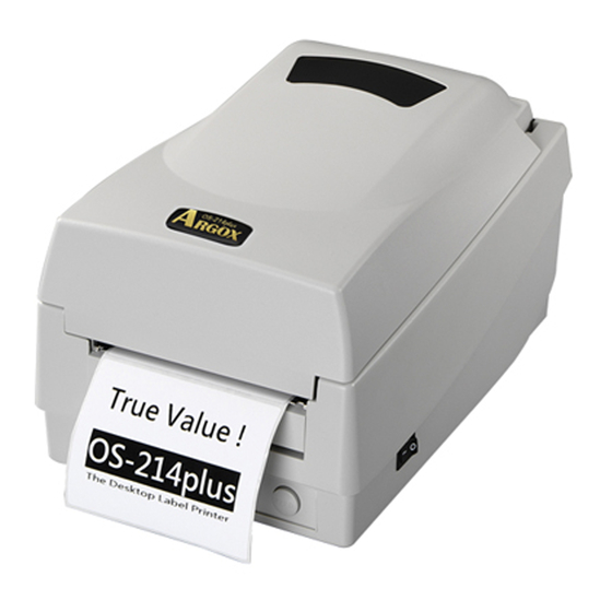
Argox OS Series Manual
Hide thumbs
Also See for OS Series:
- User manual (46 pages) ,
- Manual instruction (21 pages) ,
- Quick installation manual (9 pages)
Table of Contents
Advertisement
Proprietary Statement
This manual contains proprietary information of Argox Information Co., Ltd. It is intended solely
for the information and use of parties operating and maintaining the equipment described herein.
Such proprietary information may not be used, reproduced, or disclosed to any other parties for
any other purpose without the expressed written permission of Argox Information Co., Ltd.
Product Improvements
Continuous improvement of products is a policy of Argox Information Co., Ltd.
specifications and signs are subject to change without notice.
FCC Compliance Statement
NOTE: This equipment has been tested and found to comply with the limits for a Class B
digital device, pursuant to Part 15 of the FCC Rules.
reasonable protection against harmful interference in a residential installation. This equipment
generates, uses, and can radiate radio frequency energy and, if not installed and used in
accordance with the instructions, may cause harmful interference to radio communications.
However, there is no guarantee that the interference will not occur in a particular installation. If
this equipment does cause harmful interference to radio or television reception, which can be
determined by turning the equipment off and on, the user is encouraged to try to correct the
interference by one or more of the following measures:
Reorient or relocate the receiving antenna.
Increase the separation between the equipment and the receiver.
Connect the equipment into an outlet on a circuit different than that to which the receiver is
connected.
Consult the dealer or an experience Radio/TV technician for help.
N O T E : This unit was tested with shielded cables on the peripheral devices. Shielded cables
must be used with the unit to insure compliance. The user is cautioned that any changes or
modifications not expressly approved by Argox Information Co., Ltd. could void the userÕs
authority to operate the equipment.
Liability Disclaimer
Argox Information Co., Ltd. takes steps to assure that its published engineering specifications
and manuals are correct; however, errors do occur. Argox Information Co., Ltd. reser ves the
right to correct any such errors and disclaims liability resulting therefrom.
No Liability for Consequential Damage
In no event shall Argox Information Co., Ltd. or anyone else involved in the creation, production,
or delivery of the accompanying product (including hardware and software) be liable for any
damages whatsoever (including, without limitation, damages for loss of business profits,
business interruption, loss of business information, or other pecuniary loss) arising out of the
use of or the results of use of or inability to use such product, even if Argox Information Co.,
Ltd. has been advised of the possibility of such damages.
These limits are designed to provide
All
Advertisement
Table of Contents

Related Manuals for Argox OS Series


Summary of Contents for Argox OS Series
- Page 1 Argox Information Co., Ltd. has been advised of the possibility of such damages.
- Page 2 A Letter to Our Customers Dear Customers Congratulation on selecting an Argox OS series printer! We believe soon you will find that you have made a cleverest choice! This booklet is a small gift from us. It is intended for helping you to know your printer better, then further to optimize it.
-
Page 4: Table Of Contents
CONTENTS Page Checking Your Box..............1 Power Supply................3 Parts and Features...............5 Loading the Ribbon............9 Loading the Media.............14 Operator Controls..............25 Performing Calibration ............27 Printing Configuration Report..........27 Resetting the Printer..............28 Hooking up the Printer and the Computer.......29 Communicate with the Printer..........32 Troubleshooting................44 Caring for Your Printer.............48 Reference Technical Information..........51 Appendix I-Installing Despenser Kit........60... -
Page 5: Checking Your Box
CHECKING YOUR BOX Checking Your Box Receiving the box of your printer , you are advised to check first for the possible shipping damage. There are two ways you can do it: 1. Inspect the outer appearances of both the box and the printer for possible damage. - Page 6 CHECKING YOUR BOX Printer Power Adapter Ribbon Sample Media User's Manual CD Rom Disk...
-
Page 7: Power Supply
POWER SUPPLY Power Supply WARNING: NEVER OPERATE THE PRINTER AND POWER SUPPLY IN AN AREA WHERE THEY CAN GET WET . AC Electrical Outlet Power Jack Power Switch Cord Barrel Connector Power Adapter... -
Page 8: Parts And Features
PARTS AND FEATURES Parts and Features Top Cover Power Switch H Cover Feed Button Power Indicator Ready Indicator Ribbon Pick-up Holder Media Hanger Release Levers... - Page 9 PARTS AND FEATURES Thermal Printhead Ribbon Supply Holder Platen Roller Power Switch Peel-off Option Cutter Option White Plastic Roller Cutter...
-
Page 10: Loading The Ribbon
LOADING THE RIBBON Loading the Ribbon N o t e : T h i s s e c t i o n i s n o t a p p l i c a b l e t o t h e d i r e c t t h e r m a l p r i n t i n g . 1. - Page 11 LOADING THE RIBBON Media Compartment Print Head Module Release Lever Release Lever Ribbon Supply Holder...
- Page 12 LOADING THE RIBBON 4. Unwrap the ribbon roll pack and separate the ribbon roll and the bare core. 5. Attach the edge of the ribbon on the bare core and wind it a little bit onto the core. 6. Insert the ribbon roll into the supply holder. ( first snap in the left side and then the right side) Ribbon Supply Holder Ribbon Roll...
- Page 13 LOADING THE RIBBON 7. Turn back the print head module and then insert the bare core into the pick-up holder.(first snap in the left side, then the right side) Ribbon Pick-up Holder Bare Core...
- Page 14 LOADING THE RIBBON 8. Turn the wheel of the print head module to ensure the ribbon is tightly wound. 9. Press down the print head module firmly till you hear a snap. Wheel Print Head Module...
-
Page 15: Loading The Media
LOADING THE MEDIA Loading the Media OS Series printers can be operated in three different options: standard, peel-off, or with a cutter. - Standard mode allows you to collect each label freely. - In peel-off mode, the backing material is being peeled away from the label as it is printed. - Page 16 LOADING THE MEDIA 2. Remove the media hanger. 3. Load the media roll onto the hanger from the left. Media Compartment Media Hanger Media Roll Media Hanger...
- Page 17 LOADING THE MEDIA 4. Click the media hanger back to the media compartment. 5. Move the media roll to the left end. 6. Move the shield to the left next to the media. Media Compartment Shield Media Roll...
- Page 18 LOADING THE MEDIA 7. Unlatch the print head module. 8. Hold the print head module upright with one hand to allow the media pass under it. Lead the media through the media guides with the other hand. 9. Lead the media over the platen roller. Print Head Module Media Guides...
- Page 19 LOADING THE MEDIA 10. Turn back the print head module and then press it down firmly till you hear a snap. 11. Close the top cover and turn on the printer or press the feed button if the printer is already on. Print Head Module Feed Button...
- Page 20 LOADING THE MEDIA Peel Off Mode (Installing the dispenser kit, please refer to the Appendix I ) Follow the common procedure of "Loading the Media"of Standard Mode from step 1 to step 8. 9. Remove approximately 6" long labels from the label backing paper. Peeler Sensor Backing Paper...
- Page 21 LOADING THE MEDIA 10. Trim the edge of the label backing paper with scissor or knife. 11. Lead the backing paper over the dispenser bar, then thread it back into the slot between the dispenser bar and H cover, ensuring that it is inserted between white plastic roller and platen roller.
- Page 22 LOADING THE MEDIA 12. Press "FEED" button and the label backing paper will come out from the slot under the H cover. 13. On OS-202 Peel-Off mode, powered on status, in case of improper installation, just keep pressing the "FEED"button to back-feed the label stock to re-install it.
- Page 23 LOADING THE MEDIA 15. Close the top cover and turn on the printer or press the "FEED" button if the printer is already on. N o t e : T h e " F E E D " b u t t o n w i l l n o t d r i v e t h e p r i n t e r t o p e e l . T h e p e e l i n g w o r k c a n b e e x e c u t e d o n l y w h e n t h e s o f t w a r e s e t t i n g i s r e a d y .
- Page 24 LOADING THE MEDIA Cutter Mode ( I n s t a l l i n g t h e c u t t e r , p l e a s e r e f e r t o A p p e n d i x I I ) Follow the same procedure as "L o a d i n g t h e M e d i a"...
- Page 25 LOADING THE MEDIA 11. Close the top cover and turn on the printer or press the "FEED" button if the printer is already on. N o t e : T h e " F E E D " b u t t o n w i l l n o t d r i v e t h e p r i n t e r t o c u t . T h e c u t t i n g w o r k c a n b e e x e c u t e d o n l y w h e n t h e s o f t w a r e s e t t i n g i s r e a d y .
-
Page 26: Operator Controls
OPERATOR CONTROLS Operator Controls Power Switch Controls printer power On-normal operation Off-the power should be turned off before connect or disconnect the communication cables and power cables Feed Button Advance the label media to first printing position Press-to advance a label Press-takes the printer out of a "pause"... - Page 27 OPERATOR CONTROLS Top Cover Power Indicator Ready Indicator Feed Button Power Switch...
-
Page 28: Performing Calibration
PERFORMING CALIBRATION AND PRINT CONFIGURATION REPORT Performing Calibration 1. Keep pressing the feed button while turning on the power, until the printing motor becomes activated. 2. The calibration has been performed while the printer automatically feed label stock for certain length. N o t e : T h i s s t e p i s v e r y i m p o r t a n t a n d m u s t a l w a y s b e c a r r i e d o u t w h e n e v e r m e d i a i s b e i n g c h a n g e d . -
Page 29: Resetting The Printer
RESETTING THE PRINTER Resetting the Printer to Factory Default Settings 1. Turn on the printer and wait for 5 or more seconds. 2. Press "Feed" button for about 10 seconds, then the "Ready" indicator and "Power" indicator will go off in order. 3. -
Page 30: Hooking Up The Printer And The Computer
HOOK UP THE PRINTER AND COMPUTER Hooking up the Printer and Computer Note : The power supply barrel connector must be inserted into the power jack on the back of the printer before connecting the communication cables. This printer comes with both a nine-pin Electronics Industries Association (EIA) RS-232 serial data interface (for OS-202, it is six pin) and a standard Centronics parallel interface. - Page 31 HOOK UP THE PRINTER AND COMPUTER Power Jack RS232 Serial Port Parallel Port...
- Page 32 HOOK UP THE PRINTER AND COMPUTER Parallel Interface Requirements The required cable (IEEE 1284-compliant is recommended) must have a standard 36-pin parallel connector on one end, which is plugged into the parallel port located on the back of the printer. The other end of the parallel interface cable connects to the printer connector at the host computer.
-
Page 33: Communicate With The Printer
COMMUNICATE WITH THE PRINTER Communicate with the Printer The bundled printer driver can be applied to all the applications under Windows 2000/98/95, and Windows NT. Through this driver you may run any popular software applications e.g. MS-Word and print out the contents by this label printer as long as they are for Windows. - Page 34 COMMUNICATE WITH THE PRINTER Installing Driver 1. Click the "Start" button. 2. Select "Settings", then select "Printers" and double click the "Add Printer" icon. Click "Next". 3. Click the "Network" or "Local" button and click the "Next" button. 4. Click "Have Disk ", click the pull-down menu to select CD ROM driver path.
- Page 35 COMMUNICATE WITH THE PRINTER N o t e s : 1 . I f y o u a r e j u s t u p d a t i n g y o u r d r i v e r , m a k e s u r e t o d e l e t e t h e p r e v i o u s v e r s i o n f i r s t .
- Page 36 COMMUNICATE WITH THE PRINTER Set the Parameters After installing the driver, you can follow the path below to set parameters: S t a r t S e t t i n g s P r i n t e r s L a b e l D r .
- Page 37 COMMUNICATE WITH THE PRINTER For Win 98 P o r t s Properties menu click "Details" select the IO port click "OK" P a p e r s i z e O r i e n t a t i o n P a p e r s o u r c e ( M e d i a t y p e ) M e d i a c h o i c e...
- Page 38 COMMUNICATE WITH THE PRINTER O u t p u t b i n ( A c c e s s o r y s e t t i n g ) Properties menu click "Paper" click "more option" select Enable/without cutter, peeler click "OK"...
- Page 39 COMMUNICATE WITH THE PRINTER C r e a t e a n e w s i z e Properties menu click "Paper" select "Custom" User-Define size set up a new size click "OK"...
- Page 40 COMMUNICATE WITH THE PRINTER For Win 2000 P o r t s Properties menu click "Ports" select the IO port click "OK" P a p e r s o u r c e ( M e d i a t y p e ) Back to Printers menu right click to get pop-up menu...
- Page 41 COMMUNICATE WITH THE PRINTER O r i e n t a t i o n Printing Reference menu click "Layout" select "Portrait" or "Landscape" click "OK" P a p e r s i z e C o p i e s M e d i a c h o i c e ( A c c e s s o r y s e t t i n g ) P a p e r / O u t p u t...
- Page 42 COMMUNICATE WITH THE PRINTER C r e a t e a n e w s i z e Printer menu right click to get pop- up menu select "Ser ver Properties" enter a form name for the new form in "Form description for"...
- Page 43 COMMUNICATE WITH THE PRINTER For NT 4.0 P o r t s Properties menu click "Ports" select the IO port click "OK" P a p e r s i z e O r i e n t a t i o n P a p e r s o u r c e ( M e d i a t y p e ) C o p i e s...
- Page 44 COMMUNICATE WITH THE PRINTER P a p e r / O u t p u t ( S p e e d ) P r i n t q u a l i t y ( D a r k n e s s ) Default Document menu click "Advanced"...
-
Page 45: Troubleshooting
TROUBLESHOOTING Troubleshooting Normally, when the printer is in abnormal condition, the "POWER" LED will keep blinking. The printing work and the communication between the host and printer will stop. To understand the problem, please check both LEDs first: A. Power and Ready LEDs blink at the same tempo Power LED Ready LED Possible... - Page 46 TROUBLESHOOTING B. Power and Ready LEDs blink alternately Power LED Ready LED Possible Solutions Remarks Problems Ribbon out Supply the ribbon roll Not applicable to direct thermal type. Ribbon jam Recover the jam Ribbon sensor Replace the ribbon sensor error C.
- Page 47 D. Miscellaneous n The host shows "Printer Time out" 1. Check if the communication cable(parallel or serial) is connected securely to your parallel or serial port on the PC and to the connector on the printer at the other end. 2.
- Page 48 TROUBLESHOOTING Poor printout quality. . The ribbon may not be qualified. . The media may not be qualified. . Adjust the Darkness(heat temperature). . Slow down the print speed. . Refer to the next chapter and clean the related spare parts. Recovery To continue your print jobs after the abnormal conditions have been corrected, simply press the panel button or restart the printer.
-
Page 49: Caring For Your Printer
CARING FOR YOUR PRINTER Caring for Your Printer Clean the following areas of the printer after 8 rolls of label stocks have been used. In each case, use a cotton bud dampened with alcohol. Do not soak the cotton bud excessively. N o t e : A l w a y s s w i t c h o f f t h e p o w e r b e f o r e c l e a n i n g . - Page 50 CARING FOR YOUR PRINTER Replacing Thermal Print Head 1. Switch off the power and wait for both LEDs to go off. 2. Unlatch the print head module. 3. Remove the ribbon. 4. Push the print head firmly into the casing and shift it to the left. It will release from the module.
-
Page 53: Reference Technical Information
REfERENCE TECHNICAL INFORMATION Ribbon types Wax, Wax/Resin and Resin Ribbon size OD 1.45 in. (37 mm); ID 0.5 in. (12.7mm); Length11 Dimension W5.3 x D9.0 W7.3 x D10.9 x H6.0 in. x H6.4 in. 1.2 kg (2.6 lbs) 1.7 kg (3.74 lbs) 1.9 kg (4.1 lbs) Weight Electrical... - Page 54 REfERENCE TECHNICAL INFORMATION 2. Fonts, Bar Codes and Graphics Specification The specifications of fonts, bar codes and graphics depend on the printer emulation. The emulation is a printer programming language, through which the host can communicate with your printer. There are two printer programming languages for models 202/204/214/314, they are P P L A and P P L B .
- Page 55 REfERENCE TECHNICAL INFORMATION Printer Programming Language B, PPLB Model Model Model Model Specification OS-202DT OS-204DT OS-214TT OS-314TT General fonts 5 fonts with different point sizes 8 bits: code page 437, 850, 852, 860, 863 Symbol sets and 865. (Code pages) 7 bits: USA, British, German, French, Danish, Italian,Spanish, Swedish and Swiss.
- Page 56 REfERENCE TECHNICAL INFORMATION 3. Interface Specifications Serial For OS-204/214/314, the RS232 connector on the printer side is a female, DB-9. Direction Definition RxData TxData Ground For OS-202, the RS232 connector is Mini Dim 6P. Direction Definition Ground RxData TxData N o t e : P i n 9 o n O S - 2 0 4 / 2 1 4 / 3 1 4 a n d p i n 1 o n O S - 2 0 2 a r e r e s e r v e d f o r K D U ( k e y b o a r d d e v i c e u n i t ) , t h e r e f o r e d o n o t c o n n e c t t h e s e p i n s i f y o u a r e u s i n g a g e n e r a l h o s t l i k e a P C .
- Page 57 REfERENCE TECHNICAL INFORMATION Connection with host: Host 25S Printer 9P Host 9S Printer 9P (PC or compatible) (PC or compatible) DTR 20 .....1 DSR DTR 4....1 DSR DSR 6 ....6 DTR DSR 6....6 DTR TX 2 ....2 RX TX 3....2 RX RX 3 ....3 TX RX 2....3 TX CTS 5....7 RTS...
- Page 58 REfERENCE TECHNICAL INFORMATION The most simple way to connect to other hosts(not PC compatible) or terminals is: Printer Terminal/Host Pin 2- RxData ... TxData Pin 3- TxData ... RxData Pin 5- Ground ... Ground In general, as long as the data quantity is not too large and you use Xon/Xoff as flow control, it will be problem free.
- Page 59 REfERENCE TECHNICAL INFORMATION Parallel (Centronics) The parallel port is a standard 36-pin Centronics. Its pin assignments are listed as following. Direction Definition Direction Definition /STROBE SELECT Data1 14,15 Data 2 Ground Data3 Ground Data4 18NC Data5 19~30 Ground Data6 Data7 /Fault Data8 33~36...
- Page 60 REfERENCE TECHNICAL INFORMATION 4. ASCII TABLE 0 NUL " XOFF # 6 ACK & 7 BEL 8 BS A LF C FF < D CR E SO > F SI...
-
Page 61: Appendix I-Installing Despenser Kit
APPENDIX - Installing Dispenser Kit Appendix 1. Turn off the printer power and unplug the printer. 2. Unwrap the PC bag of dispenser kit to take out the screw, the shaft, the plastic roller, the dispenser bar, the direction label and the peeler sensor cable. - Page 62 APPENDIX 6. Route the peeler sensor cable through the guides along the left side of the top cover. 7. Fix the sensor cable and sensor board with Loctite-444 instant adhesive or equivalent. Sensor Cable...
- Page 63 APPENDIX Middle Cover 8. Release the two screws at the bottom of the base housing. 9. Remove the middle cover. 10. Take off the H Cover. 11. Tape the direction label on the top of the H cover with the arrow sign heading toward the opposite of you.
- Page 64 APPENDIX Base Housing 13. Release the screw on the left bracket of the chassis. Screw Bracket 14. Unlatch the print head module. Hook the white roller on the brackets of the chassis, ensuring the long thinner end at the left side.
- Page 65 APPENDIX 17. Hook the dispenser bar on the brackets of the chassis, positioning it above the white roller. Ensure that the dispenser bar is paralleled with the black platen roller and it's long thinner end is at the left. 18. Secure back the screw on the left bracket of the chassis. 19.
- Page 66 APPENDIX 19. Click the top cover back to the middle cover. 20. Insert the sensor connector into its receptacle on the main logic board of the base housing. 21. Click the middle cover back to the base housing. First click in the front part then the rear.
-
Page 67: Appendix I I-Installing Cutter
APPENDIX Appendix - Installing the Cutter 1. Turn off the printer power, unplug the power cable and Centronics / Serial cable. 2. Remove the top cover. 3. Remove two screws at base housing. - Page 68 APPENDIX 4. Remove the whole print head assembly by releasing 4 screws at its feet. Print Head Assembly...
- Page 69 APPENDIX 5. Add a driver IC to U19 on the main board. 6. Secure four attached screws for the cutter. Cutter 7. Plug the cutter's connector into the PCB's header connector (JP13). 8. Reinstate the print head assembly by securing back the 4 screws. 9.