Table of Contents
Advertisement
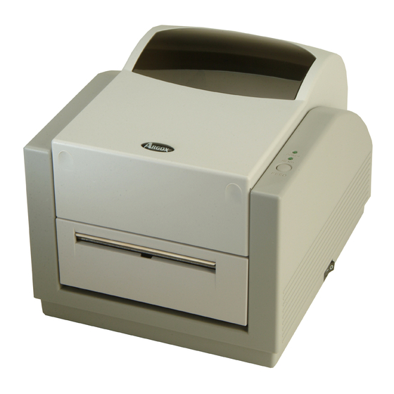
1. Checking Your Box
Receiving the box of your printer
check first for the possible shipping damage. There are two ways
you can do it:
1. Inspect the outer appearances of both the box and the printer
for possible damage.
2. Raise the top cover of the printer to see if the media
compartments are in order.
If damages did occur, immediately file the claim to the shipping
company for settlement.
Having performed the primary inspections,
step, please check whether you have received the following
accessories together with the printer. If there is any item missing,
contact your local dealer to get it.
you are advised to
,
next
1
Printer
User's Manual
CD Rom Disk
* Not available for A-50
* Sample Media
* Ribbon
Power Adapter
2
Advertisement
Table of Contents

Related Manuals for Argox A-50


Summary of Contents for Argox A-50
- Page 1 If there is any item missing, contact your local dealer to get it. User’s Manual Power Adapter CD Rom Disk * Not available for A-50...
-
Page 2: Power Supply
2. Power Supply 3. Parts and Features WARNING: NEVER OPERATE THE PRINTER AND POWER SUPPLY IN AN AREA WHERE THEY CAN GET WET. Ready Indicator 1. The Power Adapter has a barrel connector on one end that Top Cover must be inserted into the power jack on the back of the printer. 2. -
Page 3: Loading The Ribbon
Note: Media Hanger This section is not applicable to the direct thermal printing. Release Levers 1. Lift the top cover to expose the media compartment. * Ribbon Pick-up Holder * Ribbon Supply Holder Thermal Printhead * Not available for A-50... - Page 4 2. Unlatch the print head module by pushing the two white release 4. Unwrap the ribbon roll pack and separate the ribbon roll and levers on the sides toward the rear. the bare core. 3. Turn over the print head module to expose the ribbon supply 5.
- Page 5 7. Turn back the print head module and then insert the bare core 8. Turn the wheel of the print head module to ensure the ribbon is into the pick-up holder. (First snap in the left side, then the right tightly wound.
-
Page 6: Loading The Media
- In cutter mode, the printer automatically cuts the label after it is printed. Standard Mode 1. Lift the top cover to expose the media compartment. Media Hanger Media Compartment Ribbon Roll (Not Available for A-50) Peeler Cover... - Page 7 6. Lead the label through the media guides with the other hand. 7. Press down the print head module firmly on both sides till you The media guide can be adjusted centrality to well fit with hear a snap. different label width. Print Head Module Media Guides...
-
Page 8: Peel Off Mode
8. Close the top cover and turn on the printer or press the feed Peel Off Mode button if the printer is already on. 1. Loose two attached screws on the back of peeler cover. 2. Remove the peeler cover. Screw Feed Button... - Page 9 3. Plug in the dispenser connecter. 5. Secure two attached screws on the back of peeler cover. 4. Mount the dispenser module. 6. Lead the label through the media guides and dispenser. Dispenser Connecter Screw Media Guides Dispenser Module Dispenser...
- Page 10 7. Press down the print head module firmly till you hear a snap. 9. Press the feed button and the label backing paper will come out from the slot under dispenser. 8. Close the top cover and turn on the printer or press the feed button if the printer is already on.
-
Page 11: Cutter Mode
Cutter Mode 4. Loose the screw on the printer module. 5. Remove the dispenser bar. 1. First plug cutter baby board in JP29 on the main board. 2. Loose two attached screws on the back of peeler cover. 3. Remove the peeler cover. Screw Screw Peeler Cover... - Page 12 6. Plug in the cutter connecter. 8. Lead the label through the media guides and the slot of cutter. 7. Secure the screw of cutter module. 9. Press down the print head module firmly on both sides till you hear a snap. Cutter Connecter Media Guides Print Head Module...
-
Page 13: Operator Controls
10. Close the top cover and turn on the printer or press the feed 6. Operator Controls button if the printer is already on. Power Switch Controls printer power Feed Button 1. On : normal operation 2. Off : the power should be turned off before connect or disconnect the communication cables and power cables Feed Button Advance the label media to first printing position... -
Page 14: Performing Calibration
7. Performing Calibration Ready Indicator Top Cover 1. Keep pressing the feed button while turning on the power, until the printing motor becomes activated. 2. The calibration has been performed while the printer automatically feed label stock for certain length. Note: This step is very important and must always be carried out whenever media is changed. -
Page 15: Printing Configuration Report
8. Printing Configuration Report 9. Returning to Factory Default Settings 1. Turn on the printer and wait for 5 or more seconds. 1. Keep pressing the feed button while turning on the power, until the printing motor has been activated. 2. -
Page 16: Hooking Up The Printer And Computer
10. Hooking up the Printer and Computer Power Jack Note : The power supply barrel connector must be inserted into the power jack on the back of the printer before connecting the communication cables. This printer comes with both a nine-pin Electronics Industries Association (EIA) RS-232 serial data interface, a standard Centronics parallel interface and USB interface (except A-150). -
Page 17: Parallel Interface Requirements
Parallel Interface Requirements 11. Communicating with the Printer The required cable (IEEE 1284-compliant is recommended) must The bundled printer driver can be applied to all the applications have a standard 36-pin parallel connector on one end, which is under Windows 98/ME/2000/XP, and Windows NT. Through this plugged into the parallel port located on the back of the printer. -
Page 18: Installing Usb Driver (Windows 98 Only)
Installing USB Driver (Windows 98 only) → Click “Next “. → Select "Specify a location". ❑ Install USB driver Properties menu → Right click to get pop-up menu. → Click “Next “. Notes: Uninstall printer driver before installing USB driver. →... -
Page 19: Installing Printer Driver
Installing Printer Driver Notes : 1. If you are just updating your driver, make sure to delete the previous version first. 1. Click the "Start" button. 2. Uninstall printer driver before installing USB driver. 2. Select "Settings", then select "Printers" and double click the 3. - Page 20 Set the Parameters For Win 98 / ME After installing the driver, you can follow the path below to set ❑ Ports parameters: Properties menu → → → → Start Settings Printers Label Dr. Properties → Click "Details". → Select the IO port. The parameters include: →...
- Page 21 ❑ Output bin ❑ Create a new size Properties menu (Accessory setting) → Click "Paper". Properties menu → Select "Custom". → Click "Paper". → User-Define size. → Click "more option". → Set up a new size. → Select Enable/without → Click "OK". cutter, peeler.
- Page 22 For Win 2000 ❑ Orientation Printing Reference menu ❑ Ports → Click "Layout". Properties menu → Select "Portrait" or "Landscape". → Click "Ports". → Click "OK". → Select the IO port. → Click "OK". ❑ Paper size ❑ Copies ❑ Media choice ❑...
- Page 23 For NT 4.0 ❑ Create a new size Printer menu ❑ Ports → Right click to get pop- up menu on empty space. Properties menu → Select "Server → Label Dr. Properties". → Click "Ports". → Enter a form name for →...
- Page 24 select desired parameter. For Win XP ❑ Paper/Output (Speed) ❑ Ports ❑ Print quality (Darkness) Properties menu Default Document menu → Click "Ports". → Select the IO port. lick "Advanced". → C → Click "OK". lick each item to → C select desired parameter.
- Page 25 ❑ Orientation ❑ Create a new size Printing Reference menu Printer menu → Click "Layout". → Right click to get → Select "Portrait" or pop-up menu in "Landscape". blank space. → Click "OK". → Select "Server Properties". → Enter a form name for the new form in "Form name”.
-
Page 26: Troubleshooting
12. Troubleshooting B. Power and Ready LEDs blink alternately Power LED Ready LED Normally, when the printer is in abnormal condition, the power LED will keep blinking. The printing job and the communication between the host and printer will stop. To understand the problem, please check both Possible Problems Solutions... - Page 27 D. Miscellaneous Poor printout quality. . The ribbon may not be qualified. The host shows "Printer Time out" . The media may not be qualified. 1. Check if the communication cable( parallel, serial or USB) is . Adjust the Darkness ( heat temperature ). connected securely to your parallel or serial port on the PC and to .
-
Page 28: Caring For Your Printer
13. Caring for Your Printer Replacing Thermal Print Head 1. Switch off the power and wait for both LEDs to go off. Clean the following areas of the printer after 8 rolls of label stocks 2. Push print head module and pull it down as the 2 arrows shown have been used. - Page 29 (12, 13). General Specifications 4. Unplug the 2 print head cables from the connectors on print head to take off the old print head. A-50 A-150 A-200 Specifications 5. Plug the 2 print head cable to the new print head.
- Page 30 Windows 1250,1251,1252,1253.1254,1255. Core size - ID 0.5” core (13 mm) with notch 7 bits: USA, British, German, French, Danish, Italian, * Ribbon is not available for A-50 Spanish, Swedish and Swiss. Build-in Tear off bar, front-open cover, clear window, fan...
-
Page 31: Interface Specifications
2. Since this printer uses band buffer technology, if you just Interface Specifications print texts or barcodes the maximum length can be more USB Interface Requirement than 30 inches, whereas if you print many graphics the maximum length can only be few inches under standard onboard RAM. -
Page 32: Connection With Host
Connection with host: Pin 3- TxData ……… RxData Pin 5- Ground ……… Ground Host 25S Printer 9P Host 9S Printer 9P In general, as long as the data quantity is not too large and you (PC or compatible) (PC or compatible) use Xon/Xoff as flow control, it will be problem free. -
Page 33: Parallel (Centronics)
Parallel (Centronics) ASCII TABLE The parallel port is a standard 36-pin Centronics. Its pin assignments are listed as following. SON XON " Direction Definition Direction Definition /STROBE SELECT XOFF Data1 14,15 Data 2 Ground Data3 Ground Data4 & Data5 19~30 Ground ‛...