Argox CP-2140Z User Manual
Compact printer
Hide thumbs
Also See for CP-2140Z:
- User manual (84 pages) ,
- Quick installation manual (4 pages) ,
- User manual (42 pages)

Related Manuals for Argox CP-2140Z


Summary of Contents for Argox CP-2140Z
- Page 1 OMPACT RINTER SERIES ’ ANUAL CP-2140 / CP-2140Z / CP-2140E CP-3140L / CP-3140ZL CP-3140LE / CP-3140ZLE V1.1-11-12-2017 service@argox.com Compact Printer Series - User’s Manual Website: http://www.argox.com...
-
Page 2: Table Of Contents
Unpacking Printer ............7 Package Contents ............ 8 Printer Overview ............9 Front View: ............... 9 Rear View: CP-2140, CP-2140Z, CP-3140L, CP-3140ZL ............10 Rear View: CP-2140E, CP-3140LE, CP-3140ZLE . 10 Interior View I ............11 Interior View II ............12 Attaching Power ............ - Page 3 Resetting Printer to Factory Defaults ......35 Printer Controls and Indicators ........36 Troubleshooting by LED Indicators Diagnosis .... 39 Miscellaneous ............. 42 Recovery ..............43 4. Communications ............44 Interfaces and Requirements ........44 USB Interface Requirements ........44 Serial (RS-232) Interface Requirements ....
- Page 4 Serial Interface ............67 Parallel (Centronics) Interface ........ 68 Ethernet Interface ........... 69 7. Appendix ..............72 Rotary Cutter and Guillotine Cutter Installation ..72 Rotary Cutter and Guillotine Cutter Settings ..78 Rotary Cutter with Paper Jam ........ 81 Guillotine Cutter with Paper Jam ......
-
Page 5: Introduction
Argox Information Co., Ltd. Product Improvements Continuous improvement of products is a policy of Argox Information Co., Ltd. All specifications and signs are subject to change without notice. FCC Compliance Statement This equipment has been tested and found to comply with the limits for a Class A digital device, pursuant to Part 15 of the FCC Rules. - Page 6 Argox Information Co., Ltd. has been advised of the possibility of such damages.
-
Page 7: Getting Started
Getting Started Congratulations on choosing CP compact printer series, made by Argox Information Co., a leader in the world-wide barcode industry. CP compact printer series are ideally designed to easily bring more efficiency for your business. This manual will help you get to know your new printer and provide sufficient information needed. -
Page 8: Package Contents
Package Contents Printer Quick Installation Guide Power Supply Power Cord USB cable Media Hanger & ields Media Sh Ribbon Core 1” ID Core for Ribbon Adaptors Quick Installation Guide Power Cord Media Hanger & Media Shields Printer ... -
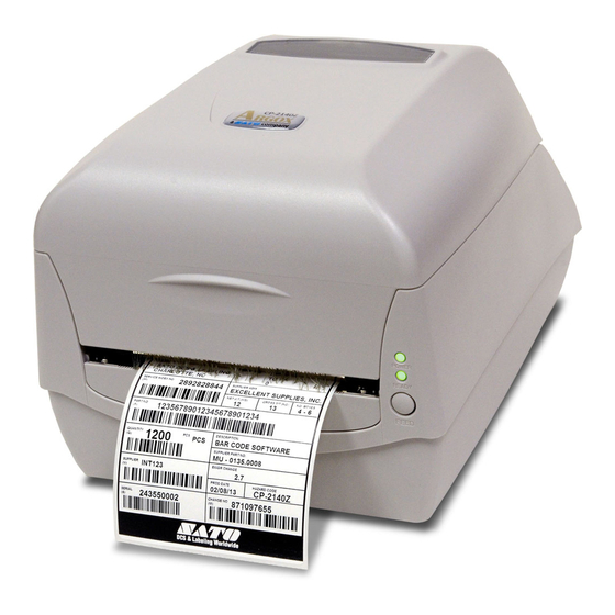
Page 9: Printer Overview
Printer Overview Front View: Top Cover Power LED Ready LED Feed Button Compact Printer Series - User’s Manual... -
Page 10: Rear View: Cp-2140, Cp-2140Z, Cp-3140L, Cp-3140Zl
Rear View: CP-2140, CP-2140Z, CP-3140L, CP-3140ZL Power Switch RS232 Serial Parallel Port Power Jack Rear View: CP-2140E, CP-3140LE, CP-3140ZLE Power Switch RS232 Serial Ethernet Power Jack Compact Printer Series - User’s Manual... -
Page 11: Interior View I
Interior View I Media Shields Ribbon Pick-up Holder Media Hanger Module Release Latch PUSH Compact Printer Series - User’s Manual... -
Page 12: Interior View Ii
Interior View II Top Cover Ribbon Supply Holder Media Shaft Print Head Transmissive Sensor Media Guides Platen Roller Power LED Reflective sensor Ready LED Front Cover Feed Button Head-Open Sensor Compact Printer Series - User’s Manual... -
Page 13: Attaching Power
4. Plug the other end of the power cord into an appropriate grounded AC electrical outlet. Warning: Do not operate the printer and power supply in an area where they might get wet. CP-2140, CP-2140Z, CP-3140L, CP-3140ZL Power Jack Power Cord Power Connector Power Supply Compact Printer Series - User’s Manual... - Page 14 CP-2140E, CP-3140LE, CP-3140ZLE Power Jack Power Connector Power Supply Power Cord Compact Printer Series - User’s Manual...
-
Page 15: Loading Media
Loading Media Preparing Media The inside wound or outside wound media rolls can be loaded into the printer in the same way. In case media roll may become dirty or dusty during shipment, handling, or storage, firstly remove the outside length of media, which helps to avoid dragging adhesive or dirty media between the print head and platen roller. - Page 16 2. Put the Media Hanger through media supply roll, and then centrally align with the two Media Shields to closely lean against the media supply roll. Media Hanger Media Shield 3. Locate the media supply roll into the Media Compartment of printer.
- Page 17 4. Push the Release Latch to open the printer module. PUSH Module Release Latch 5. Pull a short length of media till it reaches the Platen Roll of printer. Platen Roller Compact Printer Series - User’s Manual...
- Page 18 6. Press the lock of Media Guide at the right to adjust media guides’ positions. Make sure media stays under the Media Shaft and centrally under both of the Media Guides. Media Shaft Media Guides 7. Close the printer module and then press firmly at the both sides to properly latch until you hear a click.
- Page 19 8. Press the FEED button to feed labels out of the printer. FEED Button 9. To tear media, pull the media edge against the Tear Bar as in the direction below: Tear Direction Tear Bar Compact Printer Series - User’s Manual...
-
Page 20: Media Sensor Type Setting
To index labels with multiple columns, please select media types to Multi-Column Labels in the label editing software Bartender UL. Software setting steps: Argox Bartender UL / Seagull Driver – Media Types – Multi-Column Labels Sample of labels with multiple columns:... -
Page 21: Multi-Column Label Setting Manually
Multi-Column Label Setting Manually With specific firmware versions, CP Series printers now get the sensor setting able to be achieved manually. Once there is need to detect multi-column labels, but there is no PC around, or utility software is not installed, or it’s necessary to over ride printer’s previous settings from commands/ software setting, the procedures provided below can be quick and easy to set Reflective Sensor Force Mode manually. - Page 22 Step 1. PUSH Module Release Latch Compact Printer Series - User’s Manual...
- Page 23 Step 2. FEED Button Compact Printer Series - User’s Manual...
- Page 24 Step 3. Mode B. After manually setting Reflective Sensor Force Mode, if it is needed to reset the printer to its default Transmissive Sensor and exit from Force Mode, refer to the steps below: 1. Push the Release Latch to open the printer module. Ready LED will start flashing.
- Page 25 ※ Before printing, to double-check current sensor setting, please conduct media calibration and print a self-test/ configuration label. Refer to the sample self-test pages below: Reflective Sensor Transmissive Sensor Force Mode Mode (See-Through Sensor) Compact Printer Series - User’s Manual...
-
Page 26: Loading Ribbon
Loading Ribbon The following steps only apply to thermal transfer printing mode only. Direct thermal does not need ribbon to be installed. Note: Media and ribbon types should be matched to provide with optimal print results. Always use ribbon that is wider than the media to protect the print head from wear. -
Page 27: Placing Ribbon Rolls
Placing Ribbon Rolls 1. Open Top Cover of the printer. Top Cover 2. Push the Release Latch to open the printer module. PUSH Module Release Latch Compact Printer Series - User’s Manual... - Page 28 3. Lift up the printer module to check the Ribbon Supply Holder. Ribbon Supply Holder Compact Printer Series - User’s Manual...
- Page 29 4. Install one ribbon roll and rotate it until the notches align and lock into the left side of Ribbon Supply hub, and then into the right. Ribbon Supply Holder Note: The Ribbon Supply Holder accepts the coated side of ribbon to be wound ink-side IN or wound ink-side OUT.
- Page 30 5. Install the other ribbon roll and rotate it until the notches align and lock into the left side of Ribbon Pick-up hub, and then the right. Ribbon Pick-up Holder Note: The Ribbon Pick-up Holder accepts the coated side of ribbon to be wound ink-side OUT only.
- Page 31 6. Close the printer module and then press firmly at the both sides to properly latch it until you hear a click. 7. Rotate Thumb Wheel of Ribbon Pick-up Holder to remove slack and ribbon wrinkle, and to align the ribbon on the spindles. Thumb Wheel Compact Printer Series - User’s Manual...
-
Page 32: Printer Operations
Release the FEED button as soon as printer starts to print. Note: If printer is with Argox PPLB printer language, printer will enter Dump mode after printing configuration. In Dump mode, all characters will be printed in 2 columns: the right shows characters received from your system, and the left are the corresponding hexadecimal values of the characters. -
Page 33: Sample Of Printer Configuration Label
Sample of Printer Configuration Label Firmware version & date code Memory capacity Codepage Print method Media sensor type Real Time Clock (RTC) setup (available only with RTC Card) Internal Asian fonts downloaded Printed label length Serial port settings Print speed and darkness Media type setting Print width setting Label length setting... - Page 34 Ethernet information - for Ethernet models only Main board DIP switch settings Print head test pattern Compact Printer Series - User’s Manual...
-
Page 35: Resetting Printer To Factory Defaults
Resetting Printer to Factory Defaults Follow the steps below to reset printer to default settings: 1. Turn on the printer and wait till both "Ready" indicator and "Power" indicator stay solid green. 2. Press the "FEED" button for 4 seconds, and the "Ready" indicator and "Power"... -
Page 36: Printer Controls And Indicators
Printer Controls and Indicators Power Switch Power LED Ready LED Feed Button The following table explains printer controls and indicators’ functions to help understanding LED indications and printer status: Compact Printer Series - User’s Manual... - Page 37 Control / Function Indicator On: turns on normal operation (at “I” position) Power Off: turns off power ( at “O” position) Switch Note: Turn power off before connecting or disconnecting cables It will start blinking while “Media Out”, “Media ...
- Page 38 opened. Note: When the print head is over-heated, printer’s thermal protection function will be activated and make READY LED blink to indicate printer is in PAUSE status to wait till print head has been cooled down. The printing tasks sent previously will be resumed automatically later.
-
Page 39: Troubleshooting By Led Indicators Diagnosis
Troubleshooting by LED Indicators Diagnosis Normally, when the printer is in not working properly, the "Power" LED blinks continuously, and printing and communication between the host and printer stops. Refer to LED indications listed below to understand possible solutions to resolve the problems printer run into. - Page 40 LED Indicators: Power and Ready LEDs blink alternately Power LED Ready LED Possible Problems Solutions Remarks Set “Direct Thermal” Ribbon out Install a new ribbon roll printing by driver or commands if no ribbon is required. LED Indicators: Only the Power LED blinks Power LED Ready LED Possible Problems...
- Page 41 LED Indicators: Only the Ready LED blinks Power LED Ready LED Possible Problems Solutions Print head needs to Printing will stop until the print head cools to cool down normal printing temperature. Once it completes, the printer will automatically resume the printing tasks sent previously.
-
Page 42: Miscellaneous
Miscellaneous If the host shows "Printer Time out": 1. Check if the communication cable (serial) is connected securely to your serial port on the PC and to the connector on the printer at the other end. 2. Check if the printer power is turned on. If the data has been sent, but there is no output from the printer. -
Page 43: Recovery
Poor printout quality: The ribbon may not be qualified. The media may not be qualified. Adjust the Darkness (heat temperature). Slow down the print speed. Refer to the next chapter and clean the related spare parts. Recovery After correcting problems, simply press the panel button or restart the printer to continue your print jobs. -
Page 44: Communications
4. Communications Interfaces and Requirements Argox CP printer series come with a nine-pin Electronics Industries Association (EIA) RS-232 serial data interface, a USB interface, Parallel, and Ethernet. A variety of interface options are suitable for versatile applications: CP-2140,CP-2140Z,CP-3140L,CP-3140ZL: Parallel, USB, and... -
Page 45: Serial (Rs-232) Interface Requirements
Serial (RS-232) Interface Requirements The required cable must have a nine-pin "D" type male connector on one end, which is plugged into the mating serial port located on the back of the printer. The other end of the signal interface cable connects to a serial port on the host computer. -
Page 46: Ethernet 10/100 Internal Printer Server Option
3. Do not tie the data cables to power wire conduits. Ethernet 10/100 Internal Printer Server Option This connector is for Ethernet application; it is convenient to use several printers by Ethernet connector at the same time. Note: When using Ethernet model printer, please wait till the Ready Indicator to stop blinking, before starting printer operations. -
Page 47: Communicating With The Printer
Windows XP/ Vista/ Windows 7/ Windows 8/ Windows 10, supporting 32-bit/ 64-bit operation systems. With this driver you can operate any popular Windows software applications including Argox Bartender UL label editing software or MS Word, etc., to print to this printer. Drivers can be downloaded from Argox website... - Page 48 Click Cancel and do not install the driver using this wizard. 3. Run the driver from Argox website. On the prompt, Windows Printer Driver, select “I accept…” and click "Next".
- Page 49 4. Assign the directory to keep Seagull driver, (for example: C:\Seagull) and click "Next". 5. Click "Finish". Compact Printer Series - User’s Manual...
- Page 50 6. Select Install printer drivers and Click "Next" 7. On the Seagull Driver Wizard prompt, select the first radio button to “Install a driver for a Plug and Play printer”: Compact Printer Series - User’s Manual...
- Page 51 Then click “Next.” 8. Enter Printer name (i.e. Argox CP-2140 PPLB) and select "do not share this printer”, and click "Next" 9. Check all the data on the showing screen, if it is correct, click "Finish". Compact Printer Series - User’s Manual...
- Page 52 10. After the related files have been copied to your system, click "Finish". 11. After driver installation is complete, click "Close". The driver should now be installed. Compact Printer Series - User’s Manual...
-
Page 53: Installing A Printer Driver (For Other Interfaces Except Usb)
Connect the Parallel cable, Serial cable, or Ethernet cable to the proper port on the printer and on your computer. 2. Run the driver from Argox website. On the prompt, Windows Printer Driver, select “I accept…” and click "Next". - Page 54 3. Assign the directory to keep Seagull driver, (for example: C:\Seagull) and click "Next". 4. Click "Finish". Compact Printer Series - User’s Manual...
- Page 55 5. Select Install printer drivers and Click "Next" 6. Make sure printer is connected to PC, select “Other” and click “Next”: Compact Printer Series - User’s Manual...
- Page 56 7. Select model & emulation - the following examples are based on model CP-2140 PPLB: 8. Select the port of the printer and click "Next". Compact Printer Series - User’s Manual...
- Page 57 9. Enter Printer name (i.e. Argox CP-2140 PPLB) and select "do not share this printer”, and click "Next". Argox CP-2140 PPLB 10. Check all the data on the showing screen, if it is correct, click "Finish". Compact Printer Series - User’s Manual...
- Page 58 11. After the related files have been copied to your system, click "Finish". 12. After driver installation is complete, click "Close". The driver should now be installed. Compact Printer Series - User’s Manual...
-
Page 59: Caring For Your Printer
Caring for Your Printer Print Head Maintenance Guide To keep the Print Head remain in the best conditions and efficiency and to extend duration for use, regular cleaning action is needed: Note: Always switch off printer power before cleaning. In case of long-time printing, surface of print head may be very hot. -
Page 60: Product Specification
When cleaning the print head, always wipe in One-Way Direction - from Left to Right only, or, from Right to Left only, to clean “Heating Line” of print head gently without excessive stress. Do not wipe back and forth, to avoid dust or dirt on cleaning cotton would be attached onto print head again. -
Page 61: General Specification
Parallel, RS-232(Baud rate: 2400~115200 bps), USB Interface CP-2140E, CP-3140LE, CP-3140ZLE: Ethernet, RS-232(Baud rate: 2400~115200 bps), USB CP-2140, CP-2140E, CP-3140L, CP-3140LE: PPLA, PPLB Emulation CP-2140Z, CP-3140ZL, CP-3140ZLE: PPLZ Software - Seagull Driver, BarTender Label editing Software – Printer Utility, Font Utility... - Page 62 thermal paper or plain paper and fabric label Max Width:4.33”(110mm) Min Width:1”(25.4mm) Thickness:0.0025”~0.01”(0.0635~0.254mm) Max roll capacity(OD):5”(127mm) Core size:1”(25.4mm) / Max roll capacity(OD):4.5”(114.3mm) Core Media size:0.5”(12.7mm) (optional) / Max roll capacity(OD):4.72”(120mm) Core size:1.5”(38.1mm) (optional) Min Length: 0.79“(20mm) for rotary cutter option Ribbon roll –...
-
Page 63: Fonts, Barcodes, And Graphics Specification
Fonts, Barcodes, and Graphics Specification The specifications of fonts, bar codes and graphics depends on the printer emulation. The emulations PPLA, PPLB, and PPLZ are printer programming languages, through which the host can communicate with your printer. Printer Programming Language PPLA Programming PPLA Language... -
Page 64: Printer Programming Language Pplb
MaxiCode、PDF417、Data Matrix (ECC 200 2D Barcodes only) 、QR code、Composite Codes Printer Programming Language PPLB Programming PPLB Language Internal fonts 5 fonts with different point size 8 bits code page : 437, 850, 852, 860, 863, 865, 857, 861, 862, 855, 866, 737, 851, 869, 1252, 1250, 1251, 1253, 1254, 1255 Symbol sets... -
Page 65: Printer Programming Language Pplz
Interleave 2 of 5、Interleaved 2 of 5 with check sum、Interleaved 2 of 5 with human readable check digit、 German Postcode、 Matrix 2 of 5、 UPC Interleaved 2 of 5、 EAN-13 2/5 digit add-on、 UPCA 2/5 digit add-on、UPCE 2/5 digit add-on、 GS1 Data bar (RSS) MaxiCode、PDF417、Data Matrix (ECC 200 2D Barcodes... -
Page 66: Interface Specification
Plessey、GS1 Data bar (RSS) 、Industrial 2 of 5、 Standard 2 of 5、Logmars MaxiCode、PDF417、Data Matrix (ECC 200 2D Barcodes only) 、QR code、Composite Codes Interface Specification This section presents the interface specifications of IO ports for the printer. These include pin assignments, protocols and detailed information about how to properly interface your printer with your host or terminal. -
Page 67: Serial Interface
Serial Interface The RS232 connector on the printer side is a female, DB-9. Signal Description No function Shorted to Pin - 6 Received Data, Input. Serial “Received Data” Output. Serial “Transmitted Transmitted Data, Data”. No function No connection Signal Ground No function Shorted to Pin - 1 Request to Send,... -
Page 68: Parallel (Centronics) Interface
Parallel (Centronics) Interface The parallel port is a standard 36-pin Centronics, which complies with IEEE 1284 standard (compatibility mode). Pin assignments are as follows: Pin Direction Definition Direction Definition /STROBE SELECT 14,15 Data1 Data 2 Ground Data3 Ground Data4 Data5 19~30 Ground Data6... -
Page 69: Ethernet Interface
Ethernet Interface The following port complies with Ethernet communication. Signal 1 2 3 4 5 6 7 Transmit+ Transmit- Receive+ Reserved Reserved Receive- Reserved Reserved Compact Printer Series - User’s Manual... - Page 70 Connection with Host Host 25S Printer 9P Host 9S Printer (PC or compatible) (PC or compatible) DTR 20 …… 1 DSR …… 1 DSR DTR 4 …… 6 DTR …… 6 DTR DSR 6 DSR 6 …… 2 RX …… 2 RX TX 2 TX 3 ……...
- Page 71 The simplest way to connect to other hosts (not PC compatible) or terminals is: Printer Terminal/Host Pin 2- RxData ……… TxData Pin 3- TxData ……… RxData Pin 5- Ground ……… Ground In general, as long as the data quantity is not too large and you use Xon/Xoff as flow control, it will be problem free.
-
Page 72: Appendix
Appendix Rotary Cutter and Guillotine Cutter Installation Warning: Blades inside cutters are quite sharp. To ensure your safety, never attempt to insert fingers or objects into rotary cutter or guillotine cutter. During all cutter operations including installation, adjustment, or recovery from paper jam, please power off printer first and unplug printer’s power cord. - Page 73 3. Loose the two screws (item 2) under Bottom (item 1). 4. Pull out to unlatch the front side of Middle Cover (item 3) and then remove it upward from Bottom . 5. Loose the four screws (item 4) at both sides of Printer Module to take Printer Module off from Bottom.
- Page 74 Pull Compact Printer Series - User’s Manual...
- Page 75 7. Remove Mylar Film from Printer Chassis. Thread Cutter Cable through the hole where Mylar Film locates, and then connect to JP9 connector (CUTTER) on printer main board. Cutter Cable should go though the hooks under Printer Chassis to manage cables better. Make sure Cutter Cable go upon the font side of Middle Cover.
- Page 76 Chassis with screws. 12. Close Printer Module and Top Cover. Now cutter installation has been completed through the steps above. To load media, please refer to the section – Loading Media. Compact Printer Series - User’s Manual...
- Page 77 Printer Module Middle Cover Compact Printer Series - User’s Manual...
-
Page 78: Rotary Cutter And Guillotine Cutter Settings
Rotary Cutter and Guillotine Cutter Settings Before printing and cutting tasks, please make sure whether the cutter in use is Rotary Cutter, or Guillotine Cutter. Then select proper settings via Seagull Driver for printer. The following installation steps are based on CP-2140 as an example. 1. - Page 79 3. “Cutter Setup” prompts will be indicated as below. Check on the radio button, “Rotary” if there’s Rotary Cutter installed. Then click “OK“: Check on the radio button, “Guillotine” if there’s Guillotine Cutter installed. Then click “OK“: Compact Printer Series - User’s Manual...
- Page 80 4. Go to “Printing Preference” prompt of CP-2140 driver and then click on the “Stock” tag. Check “Post-Print Action” settings and select “Cut”. ※ If there’s Guillotine Cutter installed and partial cut function is needed, select “Partial Cut” in “Post-Print Action”. Compact Printer Series - User’s Manual...
-
Page 81: Rotary Cutter With Paper Jam
Rotary Cutter with Paper Jam If there is paper jam inside rotary cutter, refer to Rotary Cutter Installation section to remove the rotary cutter. Check the Cam as marked in Figure 1; find a slotted screwdriver to turn counter-clockwise as Figure 2. During turning the Cam of cutter, release the blade from paper and them remove the paper from the cutter. -
Page 82: Guillotine Cutter With Paper Jam
Guillotine Cutter with Paper Jam If there is paper jam inside guillotine cutter, check in Figure 2 and find where the screw under guillotine cutter. It is to control cut actions of guillotine cutter. Find a Phillips screwdriver to lay down the blade by turning the screw as directions marked in the figures.