Argox iX4 Series User Manual
Hide thumbs
Also See for iX4 Series:
- Installation manual (2 pages) ,
- Quick installation manual (2 pages) ,
- Installation manual (2 pages)
Table of Contents
Advertisement
Advertisement
Table of Contents

Related Manuals for Argox iX4 Series


Summary of Contents for Argox iX4 Series
- Page 1 Series Printer User Manual http://www.argox.com...
-
Page 2: Liability Disclaimer
Argox Corporation takes steps to assure that the company’s published engineering specifications and manuals are correct; however, errors do occur. Argox reserves the right to correct any such errors and disclaims any resulting liability. In no event shall Argox or anyone else involved in the... - Page 3 In this case, the user is encouraged to try to correct the interference by effective measures. Caution Any changes or modifications not expressly approved by the party responsible for compliance could void the user's authority to operate the equipment. All rights reserved. Copyright © 2017 Argox Information Co., Ltd...
-
Page 4: Table Of Contents
Contents Introduction ......................1 Features ....................... 1 Unpacking ....................2 Understand your printer ................3 1.3.1 Perspective view ................3 1.3.2 Back view ..................4 1.3.3 Interior view ................... 5 Printer control panel ................... 6 1.4.1 Status lights ..................6 1.4.2 Buttons ................... - Page 5 Maintenance ......................69 Cleaning ..................... 70 4.1.1 Printhead ..................70 4.1.2 Platen Roller ................. 71 RTC Battery Replacement ................72 Troubleshooting ....................73 Printer issues ..................... 73 Media issues ....................74 Ribbon issues..................... 75 Other issues ....................76 Specifications ....................... 77 Printer......................
-
Page 6: Introduction
1 Introduction Features 1 Introduction Thank you for purchasing an Argox iX4 Series industrial barcode printer. This manual provides information about how to set up and operate your printer, load media, ribbon and solve common problems. Illustrations are provided to help you quickly become familiar with the printer. -
Page 7: Unpacking
When you receive the printer, open the package immediately and inspect for shipping damage. If you discover any damage, contact the shipping company and file a claim. Argox is not responsible for any damage incurred during shipping. Save all package materials for the shipping company to inspect. -
Page 8: Understand Your Printer
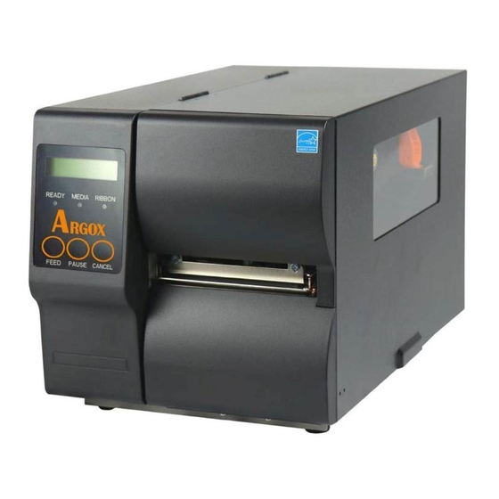
1 Introduction Understand your printer 1.3 Understand your printer 1.3.1 Perspective view Control panel Top Access Door... -
Page 9: Back View
1 Introduction Understand your printer 1.3.2 Back view Standard Ethernet USB Type A USB Type B RS232 Serial Power switch AC power connector Optional WIFI Parallel port GPIO... -
Page 10: Interior View
1 Introduction Understand your printer 1.3.3 Interior view Internal Parts and Features Ribbon Supply Spindle Ribbon Pick-up Spindle Media Supply Spindle Feed Slot Rotate Head Latch Head Latch Thermal Print Head Paper Sensor Guide Paper Roller Outside Media Guide... -
Page 11: Printer Control Panel
1 Introduction Printer control panel 1.4 Printer control panel There are three lights on the front panel - READY, MEDIA and RIBBON. These indicators display operation status of the printer. Three Buttons – FEED, PAUSE, CANCEL can control printer simple function. 1.4.1 Status lights Status lights help you check printer’s condition. - Page 12 1 Introduction Printer control panel LCD Display READY MEDIA RIBBON Description CANCEL ... Blinking ON Press CANCEL KEY to interrupt and delete a print task CLEAR FLASH Blinking ON Clear flash memory. CUTTER Blinking ON Cutter has failed, or there is paper FAILED jam inside the cutter.
-
Page 13: Buttons
1 Introduction Printer control panel LCD Display READY MEDIA RIBBON Description CALIBRATION . Blinking Blinking Press PAUSE KEY + POWER ON to calibrate media. MEDIA OUT Blinking Blinking Media is not installed or used up. Printer fails to detect the media gap. -
Page 14: Get Started
2 Get started Attach the power cord 2 Get started This chapter describes how to set up your printer. 2.1 Attach the power cord 1. Make sure the power switch is set to the OFF position. 2. Place the printer within cable distance of the host and printer (USB or Serial cable.) 3. -
Page 15: Turn On/Off Your Printer
2 Get started Turn on/off your printer 2.2 Turn on/off your printer When your printer is connected to a host (a computer), it is good to turn on the printer before turning on the host, and turn off the host before turning off the printer. -
Page 16: Turn Off Your Printer
2 Get started Turn on/off your printer 2.2.2 Turn off your printer 1. Make sure READY、MEDIA、RIBBON are solid blue before turning off the printer. 2. To turn off your printer, turn off the Power Switch as below. The “O” is the OFF position. -
Page 17: Load Media
2 Get started Load media 2.3 Load media The iX4 Series printers offer three different loading modes: standard, peel-off, or with a cutter. Standard mode allows you to collect each label freely. Peel-off mode peels backing material away from the label as it prints. After ... -
Page 18: Prepare Media
2 Get started Load media 2.3.1 Prepare media The inside wound and outside wound media roll can be loaded into the printer the same way. In case the media roll is dirty during shipping, handling or storage, remove the outside length of the media. It helps avoid dragging adhesive and dirty media between the printhead and platen roller. -
Page 19: Placing Media Roll
2 Get started Load media 2.3.2 Placing media roll Load Media In Standard Mode Lift the top cover to expose the media compartment. Door Insert the media roll into the media supply spindle and move the media guide to the inside. Media Guide Media Supply... - Page 20 2 Get started Load media Turn the head latch counter-clockwise and open the outside media guide counter-clockwise for media insert. Head Latch Outside Media Guide 4. Label must face up when lead the media through the print head module. Media is under “media guide”...
- Page 21 2 Get started Load media 5. Return the outside media guide and hook the head latch. Head Latch Outside Media Guide 6. Close the top cover.
- Page 22 2 Get started Load media 7. Press the FEED button if the printer is already on. Important After the media is loaded, please perform media calibration to calibrate the label sensor before printing. Make sure the die-cut media’s label length is at least 25mm or Note longer, for direct thermal printing in tear-off mode with perforation.
- Page 23 2 Get started Load media Load Media In Peel Off Mode Steps 1 to 3 are the similar with “Standard Mode”. 1. Lift the top cover to expose the media compartment. 2. Insert the media roll into the media supply spindle and move the media guide to the inside.
- Page 24 2 Get started Load media Push down the peel-off mechanism release lever and lead the media backing paper behind the peeler module. Media Peel Lever Close the peeler module using the peel-off mechanism release lever. Return the outside media guide and hook the head latch. Head latch Outside media guide Peeler lever...
- Page 25 2 Get started Load media Close the top cover and turn on the printer or press the FEED button if the printer is already on. Important After the media is loaded, please perform media calibration to calibrate the label sensor before printing.
- Page 26 2 Get started Load media Load Media In Rotary Cutter Mode Steps 1 to 3 are the similar with “Standard Mode”. Lift the top cover to expose the media compartment. Insert the media roll into the media supply spindle and move the media guide to the inside.
- Page 27 2 Get started Load media Return the outside media guide and hook the head latch. Head Latch Outside Media Guide Close the top cover and turn on the printer or press the FEED button if the printer is already on. The printer will then feed the labels through the cutter automatically.
- Page 28 2 Get started Load media Load Media In Guillotine Cutter Mode Steps 1 to 3 are the similar with “Standard Mode”. Lift the top cover to expose the media compartment. Insert the media roll into the media supply spindle and move the media guide to the inside.
- Page 29 2 Get started Load media Push back Guillotine Cutter and return the outside media guide and hook the head latch. Head Latch Outside Media Guide Close the top cover and turn on the printer or press the FEED button if the printer is already on.
-
Page 30: Media Types
2 Get started Load media 2.3.3 Media types Your printer supports various media types, including non-continuous media, continuous media, and fanfold media. The following table provides details about them. Media Type Looks Like Description Non-Continuous Non-continuous media is the typical media for Media bar code printing. - Page 31 2 Get started Load media Media Type Looks Like Description Continuous Continuous media does not have gaps, holes, Media notches or black marks. It allows you to print data anywhere on the media. A cutter may be used for splitting labels. Mostly it is used for direct thermal printing.
-
Page 32: Load Ribbon
2.1 Load Ribbon The following steps only apply to thermal transfer printing mode. Direct thermal does not need ribbon to be installed. iX4 Series printers apply to both Inside wound ribbon and Outside wound ribbon. Printers can switch automatically. Note Media and ribbon types should be matched to provide with optimal print results. -
Page 33: Placing Ribbon Roll
2 Get started Load Ribbon 2.1.1 Placing Ribbon Roll 1. Lift the top cover to expose the media compartment. 2. Turn the head latch counter-clockwise. Head latch... - Page 34 2 Get started Load Ribbon 3. Unwrap the ribbon and separate the ribbon roll from the bare core. Insert the ribbon roll onto the ribbon supply spindle. Ribbon Supply Spindle 4. Lead the ribbon through the print head module. Attach the edge of the ribbon onto the bare core and wind it a bit onto the core.
- Page 35 2 Get started Load Ribbon 5. Insert the core onto the ribbon pick-up spindle. Turn the pick-up spindle to ensure the ribbon is tightly wound. Ribbon Pick-up spindle 6. Close the top cover and turn on the printer.
-
Page 36: Printer Operation
3 Printer operation Front Panel 3 Printer operation This chapter provides more specific information about printer operation. 3.1 Front Panel Change settings via buttons on panel: Buttons Function PAUSE+CANCEL Press to enter setting mode. Press again to exit setting mode and return to normal mode. FEED Press to show next parameter. -
Page 37: Lcd Function Setting Procedure
3 Printer operation Front Panel 3.1.1 LCD Function Setting Procedure The following procedure is an example of setting procedure to direct thermal printing mode: READY (203, AUTO) Press both PAUSE + CANCEL buttons. Then release the buttons to enter settings. PRINT MODE Function which has “*”... - Page 38 3 Printer operation Front Panel Press over 5 seconds to set different languages. PAUSE + CANCEL Item Range Factory Default LANGUAGE ENGLISH, ENGLISH FRENCH, GERMAN, ITALIAN, SPANISH, PORTUGUESE, Press less then 1 second to set printer function. PAUSE + CANCEL Factory Item Range...
- Page 39 3 Printer operation Front Panel TPH VER OFFSET -009~009 mm 000 mm To adjust offset of vertical print position. RECOVER ENABLE, Will not reprint after recovering from ENABLE media-out or ribbon-out errors. PRINT DISABLE CUTTER (Restart printer after change setting) INSTALLED PEELER INSTALLED...
- Page 40 3 Printer operation Front Panel 2400/ 4800 Should be as same as setting of host. 9600 / 19200 / BAUD RATE 9600 38400 / 57600 / (Restart printer after change setting) 115200 NONE Should be as same as setting of host. PARITY (RS232) NONE (Restart printer after change setting)
- Page 41 3 Printer operation Front Panel LAST SAVED: NO.1~15, NO.17, NO.22, NO.24~25 and language will be loaded. LAST SAVED FACTORY: LAST SAVED LOAD DEFAULTS FACTORY NO.1, NO6, NO9, NO11, NO14~15, NO17, NO.27~30 will be loaded. NETWORK NETWORK: NO.27~30 will be loaded. (Restart printer after change setting)
- Page 42 3 Printer operation Front Panel Ethernet settings and parameters Item Range Factory Default Remarks DHCP DISABLE If printer has been connected to a router, IP address will be assigned automatically by DHCP server after power on. ENABLE If printer is not connected to a router, with DHCP disabled, settings of IP ADDRESS, SUBNET MASK, and DEFAULT GATEWAY settings will be available on LCD.
- Page 43 Item Range Remarks WIFI SSID Read only WIFI module is an option for iX4 Series. Connect printer to WIFI IP PC and use print tool to set WIFI module. To have more Read only ADDRESS information, please refer to Print Tool user guide.
-
Page 44: Printing Media Calibration & Configuration
3 Printer operation Printing Media Calibration & Configuration Printing Media Calibration & Configuration Before calibration, be sure media and ribbon (for thermal transfer printing) have been loaded correctly. The label sensor needs to locate properly to index labels’ gaps/ notches/ holes. After the media is loaded, please perform media calibration to calibrate the label sensor in advance. -
Page 45: Printing A Configuration Report
3 Printer operation Printing a Configuration Report 3.3 Printing a Configuration Report To perform a self-test and print a configuration report, helping to check printer’s print quality and internal settings. Steps as below: 1. Turn off the printer. 2. Load media and ribbon. 3. - Page 46 3 Printer operation Printing a Configuration Report...
- Page 47 3 Printer operation Printing a Configuration Report 1. Version Information The firmware version and its build date. 2. Standard RAM Total SDRAM size. 3. Available RAM RAM is able to be used. 4. Flash Type The flash memory type and size. 5.
- Page 48 3 Printer operation Printing a Configuration Report 16. Speed The speed of printing. The unit is inch per second (ips). 17. Darkness The current darkness. 18. Print Method It is either thermal transfer (TT) or direct thermal (DT) printing. TT requires ribbons and DT doesn't.
- Page 49 3 Printer operation Printing a Configuration Report Enable or disable the cutter during the printing process. 27. Dispenser Enabled/Disabled Enable or disable the dispenser during the printing process. 28. Cutter/Dispenser Offset Move the cutting line or the peeling position forward or backward. The value in the angle brackets is the offset unit.
- Page 50 3 Printer operation Printing a Configuration Report It is the IPv6 address type of your printer. There are four types: NONE, NORMAL, EUI and ANY. 41. IPv6 Address The static IPv6 address of your printer. 42. Link Local The IPv6 address that used in a network segment. It is allocated automatically.
- Page 51 3 Printer operation Printing a Configuration Report If your printer has a Wi-Fi module, your PPLB configuration label will contain the following entries: 1. FW Version WLAN board firmware version. 2. Date WLAN board firmware version date. 3. IP Address The IP address of your printer.
- Page 52 3 Printer operation Printing a Configuration Report 10. SSID Short for service set identifier. It is the name of a wireless local area network. 11. Mode There are ad-hoc and infrastructure mode. Refer to Print Tool Network type description from Technical manual. 12.
- Page 53 3 Printer operation Printing a Configuration Report PPLA...
- Page 54 3 Printer operation Printing a Configuration Report PPLZ...
-
Page 55: Resetting To Factory Default Settings
3 Printer operation Resetting to Factory Default Settings Resetting to Factory Default Settings Be cautioned that this will reset all printer settings back to defaults; if possible, print the configuration label in advance before reset. All settings stored in FLASH memory are retained even after turning off the printer. -
Page 56: Media Sensing
3 Printer operation Media sensing 3.5 Media sensing Printer offer two types of media sensor: transmissive and reflective. They are used for detecting specific media types. Both sensor types are installed together as a movable module. 3.5.1 Transmissive sensor The transmissive sensor is used for detecting gaps across the entire width of the label. -
Page 57: Reflective Sensor
3 Printer operation Media sensing 3.5.2 Reflective sensor The reflective sensor detects gaps, notches and black marks. Multi Columns Notch Black Mark Flip the media so the black-mark side is facing down to align with the sensor. -
Page 58: Adjust Position Of Label Sensor
3 Printer operation Media sensing 3.5.3 Adjust Position of Label Sensor Function of the label sensor is to detect the gap, notch, or holes of labels, to help the printer for accurate print positions and label length. For labels with gaps, label sensor can be positioned wherever media locates. -
Page 59: Communications
3 Printer operation Communications 3.6 Communications 3.6.1 Interfaces and Requirements This printer comes with USB type A and type B interface, a nine-pin Electronics Industries Association (EIA) RS-232 serial data interface, a standard Centronics parallel interface(Option), GPIO interface(Option), . USB Interface Requirements The Universal Serial Bus (USB) interface is compatible with your existing PC hardware. -
Page 60: Ethernet Module Status Indicators
3 Printer operation Communications General-purpose input/output (GPIO) Pins depend on usage and the signal is user selectable. The function is diversity. For general-purpose, I/O signals programmed as inputs can cause CPU interrupted. For more information, contact local dealer. Ethernet Module Status Indicators The indicators with two different colors help users understand status of Ethernet: Description Status... -
Page 61: Driver Installation
With this driver you can operate any popular Windows software applications including Argox Bartender UL label editing software or MS Word, etc., to print to this printer. Drivers can be downloaded from Argox website >> Technical Support >> Download Center >> select product model to access: http://www.argox.com/content.php?sno=0000033... -
Page 62: Installing A Plug And Play Printer Driver (For Usb Only)
3 Printer operation Driver installation 3.7.1 Installing a Plug and Play printer driver (for USB only) Note: We strongly recommend that you use the Seagull Driver Wizard instead of the Microsoft Windows Add Printer Wizard when installing and updating your Drivers by Seagull. (Even though the "Add Printer Wizard"... - Page 63 3 Printer operation Driver installation 3. Run the driver from Argox website. On the prompt, Windows Printer Driver, select “I accept…” and click "Next". 4. Assign the directory to keep Seagull driver, (for example: C:\Seagull) and click "Next".
- Page 64 3 Printer operation Driver installation 5. Click "Finish". 6. Select Install printer drivers and Click "Next"...
- Page 65 7. On the Seagull Driver Wizard prompt, select the first radio button to “Install a driver for a Plug and Play printer” Then click “Next.” 8. Enter Printer name (i.e. Argox iX4-250 PPLB) and select "do not share this printer”, and click "Next"...
- Page 66 3 Printer operation Driver installation 9. Check all the data on the showing screen, if it is correct, click "Finish". 10. After the related files have been copied to your system, click "Finish".
- Page 67 3 Printer operation Driver installation 11. After driver installation is complete, click "Close". The driver should now be installed.
-
Page 68: Installing A Printer Driver (For Other Interfaces Except Usb)
Connect the Parallel cable, Serial cable, or Ethernet cable to the proper port on the printer and on your computer. 2. Run the driver from Argox website. On the prompt, Windows Printer Driver, select “I accept…”and click "Next". - Page 69 3 Printer operation Driver installation 3. Assign the directory to keep Seagull driver, (for example: C:\Seagull) and click "Next". 4. Click "Finish".
- Page 70 3 Printer operation Driver installation 5. Select Install printer drivers and Click "Next" 6. Make sure printer is connected to PC, select “Other” and click “Next”:...
- Page 71 3 Printer operation Driver installation 7. Select model & emulation - the following examples are based on model iX4-250 PPLB: 8. Select the port of the printer and click "Next".
- Page 72 3 Printer operation Driver installation 9. Enter Printer name (i.e. Argox iX4-250 PPLB) and select "do not share this printer”, and click "Next". 10. Check all the data on the showing screen, if it is correct, click "Finish".
- Page 73 3 Printer operation Driver installation 11. After the related files have been copied to your system, click "Finish". 12. After driver installation is complete, click "Close". The driver should now be installed.
-
Page 74: Maintenance
4 Maintenance Driver installation 4 Maintenance Vertical streaks in the printout usually indicate a dirty or faulty print head. (Refer to the following examples.) Clean the print head. If the problem persists, replace the print head. For unstable ribbon roll rotation, check the label path and make sure the head latch is securely closed. -
Page 75: Cleaning
4 Maintenance Cleaning 4.1 Cleaning To maintain print quality and prolong the printer’s life, you need to perform some routine maintenance. Daily maintenance should be done for high volume printing, and weekly for low volume printing. Warning Always turn off the printer before cleaning. 4.1.1 Printhead It is essential to keep printhead clean if you want the best print quality. -
Page 76: Platen Roller
4 Maintenance Cleaning 4.1.2 Platen Roller The platen roller is also important for print quality. Dirty platen roller may damage the printhead. Clean the platen roller right away if the adhesive, dirt or dust accumulates on it. 1. Moisten a soft cloth with absolute ethyl alcohol. 2. -
Page 77: Rtc Battery Replacement
4 Maintenance RTC Battery Replacement 4.2 RTC Battery Replacement RTC stands for real-time clock. It is a battery powered clock that keep track of the current date and time. If your printer has a built-in RTC, you’ll find the RTC battery on the main board. -
Page 78: Troubleshooting
5 Troubleshooting Printer issues 5 Troubleshooting This chapter provides the information about printer problems and solutions. 5.1 Printer issues The printer won’t turn on ■ Did you attach the AC power cord? ■ Check the power connection from the wall socket to the printer. Test the power cord and the socket with other electrical devices. -
Page 79: Media Issues
5 Troubleshooting Media issues 5.2 Media issues The media is out ■ Load a new media roll. The paper is jammed ■ Open the printer and clear the jammed paper. ■ Make sure the paper is held properly by the Media Guides. The printing position is not correct ■... -
Page 80: Ribbon Issues
5 Troubleshooting Ribbon issues 5.3 Ribbon issues The ribbon is out ■ Load a new ribbon roll. The ribbon is broken ■ Check the print darkness and adjust it if it is too high, and take the following steps to fix the broken ribbon: Unload the ribbon supply roll and take-up roll from the printer. -
Page 81: Other Issues
5 Troubleshooting Other issues 5.4 Other issues There are broken lines in the printed label ■ The printhead is dirty. Clean the printhead. The printhead temperature is extremely high ■ The printhead temperature is controlled by the printer. If it is extremely high, the printer will stop printing automatically, until the printhead is cool down. -
Page 82: Specifications
6 Specifications Printer 6 Specifications This chapter provides specifications for the printer. 6.1 Printer iX4-250 iX4-350 Model Print method Direct Thermal & Thermal Transfer Resolution 203 dpi (8 dots/mm) 300 dpi (12 dots/mm) Standard: Continuous mode, Tear-off mode Operation Mode Optional: Cutter mode, Peeler mode Media Reflective sensor x 1 (movable) &... - Page 83 6 Specifications Printer Model iX4-250 iX4-350 Agency Listing CE, FCC, CB/LVD, cULus, ICES, Energy Star Note Print quality and speed is based on 15% print coverage.
-
Page 84: Media & Ribbon
6 Specifications Media & Ribbon 6.2 Media & Ribbon Properties Description Media Size Max. width:4.4” (112mm). Min. width: 1” (25.4 mm). Thickness:0.0025”~0.01” (0.0635mm~0.254mm) 8.26”(210mm) OD on a 3”(76mm) ID core. 7”(177.8mm) OD on a 1.5”(38mm) ID core. Min. width 2.3” (58mm)for partial cutter options. Min. -
Page 85: Electrical And Operating Environment
Size and Weight Size W 250mm x H 263mm x D 418 mm Weight 11 kg(24lbs) Note The specifications may be changed at any time without prior notice. For more information about the new specifications, visit Argox website or contact your dealer. -
Page 86: Fonts, Barcodes, And Graphics Specification
6 Specifications Fonts, Barcodes, and Graphics Specification 6.5 Fonts, Barcodes, and Graphics Specification The specifications of fonts, bar codes and graphics depends on the printer emulation. The emulations PPLA, PPLB, and PPLZ are printer programming languages, through which the host can communicate with your printer. Printer Programming Language PPLA Programming Language PPLA... -
Page 87: Printer Programming Language Pplb
6 Specifications Fonts, Barcodes, and Graphics Specification Printer Programming Language PPLB Programming Language PPLB Internal fonts 5 fonts with different point size 8 bits code page : 437, 850, 852, 860, 863, 865, 857, 861, 862, 855, 866, 737, 851, 869, 1252, 1250, 1251, 1253, 1254, 1255 Symbol sets 7 bits code page: USA, BRITISH, GERMAN,... -
Page 88: Printer Programming Language Pplz
6 Specifications Fonts, Barcodes, and Graphics Specification Printer Programming Language PPLZ Programming Language PPLZ 8 (A~H) fonts with different point size. 8 AGFA fonts: 7 (P~V) fonts with fixed different Internal fonts point size (not scalable). 1 (0) font with scaling point size. USA1, USA2, UK, HOLLAND, DENMARK/NORWAY, SWEDEN/FINLAND, GERMAN, FRANCE1, FRANCE2, ITALY,... -
Page 89: Interfaces
6 Specifications Interfaces 6.6 Interfaces This section provides information about IO port specifications for the printer. 6.6.1 USB There are two common USB connectors. Typically, type A is found on hosts and hubs; type B is found on devices. The figure below shows their pinouts. Type A Type B Signal... -
Page 90: Rs-232C
6 Specifications Interfaces 6.6.2 RS-232C The RS-232C on the printer is DB9 female. It transmits data bit by bit in asynchronous start-stop mode. The figure below shows its pinout. Signal Description Reserved for (External Device) Transmit Receive No Connection Ground Shorted to Pin 8 Clear to Send Request to Send... -
Page 91: Centronics
6 Specifications Interfaces 6.6.3 Centronics The 36-pin Centronics on the printer uses parallel communication, and complies with IEEE 1284 compatibility mode (also called SPP, Standard Parallel Port). The figure below shows its pinout. Signal Signal Signal Signal Direction Direction To Printer /STROBE S-GND Signal-GND... -
Page 92: Ethernet
6 Specifications Interfaces 6.6.4 Ethernet The Ethernet uses RJ-45 cable, which is 8P8C (8-Position 8-Contact). The figure below shows its pinout. 1 2 3 4 5 6 7 8 Signal Transmit+ Transmit- Receive+ Reserved Reserved Receive- Reserved Reserved...