
Related Manuals for Argox D4 250


Summary of Contents for Argox D4 250
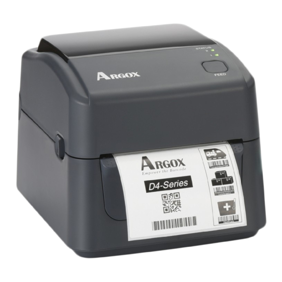
- Page 1 D4 SERIES Printer User’s Manual D4 250 / D4 350 http://www.argox.com service@argox.com V1.2-06-10-2017...
- Page 2 FCC ID In a domestic environment this product may cause radio interference in which case the user may be required to take adequate measures. FCC Warning This equipment has been tested and found to comply with the limits for a Class A digital device, pursuant to Part 15 of the FCC Rules.
- Page 3 ∙ Disassemble or modify this product. ∙ Remove the certificate label (serial number seal) affixed to this product. Use of this product near microwave and/or other Wireless LAN LAN equipment, or where static electricity or radio interference is present, may shorten the communication distance, or even disable communication.
-
Page 4: Liability Disclaimer
ARGOX Corporation takes steps to assure that the company’s published engineering specifications and manuals are correct; however, errors do occur. ARGOX reserves the right to correct any such errors and disclaims any resulting liability. In no event shall ARGOX or anyone else involved in the... -
Page 5: Table Of Contents
Contents Introduction ......................2 Features ....................... 2 Unpacking ....................2 Understand your printer ................3 1.3.1 Perspective view ................3 1.3.2 Back view ..................4 1.3.3 Interior view ................... 5 Printer lights ....................6 1.4.1 Status lights ..................6 1.4.2 System mode .................. - Page 6 4.1.3 Sensor................... 42 4.1.4 Platen roller .................. 43 Troubleshooting ....................44 Printer issues ..................... 44 Media issues ....................45 Other issues ....................46 Specifications ....................... 47 Printer......................47 Media ......................49 Fonts, Barcodes, and Graphics Specification ..........50 Wireless LAN ..................... 53 Bluetooth....................
-
Page 7: Features
1 Introduction Features 1 Introduction Thank you for purchasing a ARGOX D4 printer. This manual provides information about how to set up and operate your printer, load the media and solve common problems. 1.1 Features ■ Various Connectivity Options USB, Ethernet, RS-232 ■... -
Page 8: Introduction
When you receive the printer, open the package immediately and inspect for shipping damage. If you discover any damage, contact the shipping company and file a claim. ARGOX is not responsible for any damage incurred during shipping. Save all package materials for the shipping company to inspect. -
Page 9: Understand Your Printer
1 Introduction Understand your printer 1.3 Understand your printer 1.3.1 Perspective view LED 2 LED 1 Feed Button Cover Open Latch... -
Page 10: Back View
1 Introduction Understand your printer 1.3.2 Back view Paper Slot Power Switch RS232 USB A USB B Power Jack Caution The areas indicated by the ellipse have sharp edges. To avoid injury, be careful not to touch them when handling the printer. Caution To avoid injury, be careful not to trap your fingers in the Paper Slot while opening or closing the Top Cover. -
Page 11: Interior View
1 Introduction Understand your printer 1.3.3 Interior view Thermal Printhead Transmissive Sensor Core Holders Media Roll Holders Media Guides Thumbscrew Reflective Sensor Platen Roller Warning The printhead becomes very hot during printing. Do not touch the printhead or touch around it directly after printing. By doing so you may get burnt. -
Page 12: Printer Lights
1 Introduction Printer lights 1.4 Printer lights There are two LED lights that show the status of your printer. 1.4.1 Status lights Status lights help you check printer’s condition. The following tables show the blinking speed of status lights and the conditions they indicate. LED image Blinking Speed Blinking Interval... - Page 13 1 Introduction Printer lights Blinking LED 2 LED 1 Description pattern The printer is ready to print. Green Green In pause. Green Green The printer is transmitting data. Green Green Green Green TPH high temperature. The printer is writing data to the flash or USB memory. Green Green The USB memory is being initialized.
- Page 14 1 Introduction Printer lights The print module is opened when the printer is Top Cover turned on. Open Cover (Thermal Head) open error during printing. Flash ROM on the CPU board error or USB memory error. USB R/W An erase error has occurred when formatting Error the USB memory.
-
Page 15: System Mode
1 Introduction Printer lights 1.4.2 System mode The system mode consists of status light color combinations. It contains a list of commands for you to select and run. To enter the system mode and run the command, do the following: 1. -
Page 16: Get Started
2 Get started Attach the power cord 2 Get started This chapter describes how to set up your printer. Caution Do not use your printer in areas exposed to splashing water or any other liquid. Caution Do not drop your printer, or place it in an area subject to humidity, vibration or shock. -
Page 17: Turn On/Off Your Printer
2 Get started Turn on/off your printer 2.2 Turn on/off your printer When your printer is connected to a host (a computer), it is good to turn on the printer before turning on the host, and turn off the host before turning off the printer. -
Page 18: Turn Off Your Printer
2 Get started Turn on/off your printer 2.2.2 Turn off your printer 1. Make sure LED 2 is off and LED 1 is solid green before turning off the printer. 2. To turn off your printer, turn off the Power Switch as below. The “O” is the OFF position. -
Page 19: Load Media
2 Get started Load media 2.3 Load media There are various types and sizes for the media roll. Load the applicable media to satisfy your need. 2.3.1 Prepare media The inside wound and outside wound media roll can be loaded into the printer the same way. -
Page 20: Place A Media Roll
2 Get started Load media 2.3.2 Place a media roll 1. Open the top cover of the printer. 2. Press the holder lock on the Media Roll Holders to slide them outward, and place the media roll between the holders. Make sure the print side is up, and the media roll is clamped tightly by the holders. - Page 21 2 Get started Load media 1 inch 1.5 inch Core Holder Thumbscrew Holder Lock...
- Page 22 2 Get started Load media 3. Pull the media until it reaches out of the printer. Thread the media under the media guides. Caution Do not ship or bring the printer while it holds a label roll. 4. Close the top cover.
-
Page 23: Test Media Feed
2 Get started Load media 2.3.3 Test media feed 1. Turn on the printer, and press the FEED button to feed a label. 2. Flip the media and tear it along the edge of the top cover. -
Page 24: Media Types
2 Get started Media types 2.4 Media types Your printer supports various media types, including non-continuous media, continuous media, and fanfold media. The following table provides details about them. Media Type Looks Like Description Non-Continuous Non-continuous media is the typical media for Media bar code printing. - Page 25 2 Get started Media types Media Type Looks Like Description Fanfold Media Fanfold media is in continuous form, but it can be used as non-continuous media, because its labels are separated by folds. Some fanfold media also has black marks or liners.
-
Page 26: Media Sensing
2 Get started Media sensing 2.5 Media sensing D4 printers offer two types of media sensor: transmissive and reflective. They are used for detecting specific media types. 2.5.1 Transmissive sensor The transmissive sensor is fixed and placed near the center of the printhead. It is used for detecting gaps across the entire width of the label. -
Page 27: Reflective Sensor
2 Get started Media sensing 2.5.2 Reflective sensor The reflective sensor is movable within the entire width of the media. It detects gaps, notches and black marks not located at the center of the media. Multi Columns Notch Black Mark Flip the media so the black-mark side is facing down to align with the sensor. -
Page 28: Printer Operation
3 Printer operation Printing Media Calibration & Configuration 3 Printer operation This chapter provides information about printer operation. 3.1 Printing Media Calibration & Configuration You will want the printer to work properly before starting your print jobs. To do this, you need to calibrate the media sensor. Printers provide transmissive and reflective sensor calibration. -
Page 29: Self Test
3 Printer operation Self test 3.2 Self test The printer can run a self test to print a configuration label, which helps you understand current settings of the printer. 1. Turn off the printer. 2. Press and hold the FEED button, and turn on the printer. 3. - Page 30 3 Printer operation Self test...
-
Page 31: Reset Your Printer
3 Printer operation Reset your printer 3.3 Reset your printer By resetting your printer, you can return your printer to the state it was in when you receive it. This can help you solve some problems caused by settings changed during the printing. Do the following to reset your printer: 1. -
Page 32: Communications
3 Printer operation Communications 3.4 Communications 3.4.1 Interfaces and Requirements This printer comes with USB type A and type B interfaces, a nine-pin Electronics Industries Association (EIA) RS-232 serial data interface and an Ethernet module. USB Interface Requirements The Universal Serial Bus (USB) interface is compatible with your existing PC hardware. The USB’s “plug and play”... -
Page 33: Ethernet Module Status Indicators
3 Printer operation Communications Ethernet Module Status Indicators The indicators with two different colors help users understand status of Ethernet: Description Status Both Off No Ethernet link detected. The printer waits for printer ready. Blinking It will take about few seconds to be ready. On: 100 Mbps link Green Speed LED... -
Page 34: Driver Installation
XP/ Vista/ Windows 7/ Windows 8/ Windows 10, supporting 32-bit/ 64-bit operation systems. With this driver you can operate any popular Windows software applications including Argox Bartender UL label editing software or MS Word, etc., to print to this printer. -
Page 35: Installing A Plug And Play Printer Driver (For Usb Only)
Connect the USB cable to the USB port on the printer and on the PC. 2. Run the driver from Argox website. On the prompt, Windows Printer Driver, select “I accept…” and click "Next". - Page 36 3 Printer operation Driver installation 3. Assign the directory to keep Seagull driver, (for example: C:\Seagull) and click "Next". 4. Click "Finish".
- Page 37 3 Printer operation Driver installation 5. Select Install printer drivers and Click "Next" 6. On the Seagull Driver Wizard prompt, select the first radio button to “Install a driver for a Plug and Play printer” Then click “Next.”...
- Page 38 3 Printer operation Driver installation 7. Enter Printer name (i.e. Argox D4-250 PPLB) and select "do not share this printer”, and click "Next" 8. Check all the data on the showing screen, if it is correct, click "Finish".
- Page 39 3 Printer operation Driver installation 9. After the related files have been copied to your system, click "Finish". 10. After driver installation is complete, click "Close". The driver should now be installed.
-
Page 40: Installing A Printer Driver (For Other Interfaces Except Usb)
Connect the Parallel cable, Serial cable, or Ethernet cable to the proper port on the printer and on your computer. 2. Run the driver from Argox website. On the prompt, Windows Printer Driver, select “I accept…”and click "Next". - Page 41 3 Printer operation Driver installation 3. Assign the directory to keep Seagull driver, (for example: C:\Seagull) and click "Next". 4. Click "Finish".
- Page 42 3 Printer operation Driver installation 5. Select Install printer drivers and Click "Next" 6. Make sure printer is connected to PC, select “Other” and click “Next”:...
- Page 43 3 Printer operation Driver installation 7. Select model & emulation - the following examples are based on model D4-250 PPLB: 8. Select the port of the printer and click "Next".
- Page 44 3 Printer operation Driver installation 9. Enter Printer name (i.e. Argox D4-250 PPLB) and select "do not share this printer”, and click "Next". 10. Check all the data on the showing screen, if it is correct, click "Finish".
- Page 45 3 Printer operation Driver installation 11. After the related files have been copied to your system, click "Finish". 12. After driver installation is complete, click "Close". The driver should now be installed.
-
Page 46: Maintenance
4 Maintenance Cleaning 4 Maintenance This chapter describes routine cleaning procedure. 4.1 Cleaning To maintain print quality and prolong the printer’s life, you need to perform some routine maintenance. Daily maintenance should be done for high volume printing, and weekly for low volume printing. Caution Always turn off the printer before cleaning. -
Page 47: Media Housing
4 Maintenance Cleaning Important Printhead warranty becomes void if printhead’s serial number is removed, altered, defected, or made illegible, under every circumstance. 4.1.2 Media housing Use a soft cloth to clean the dust, dirt or debris built up on the Media Roll Holders, Media Guides and media path. -
Page 48: Sensor
4 Maintenance Cleaning 4.1.3 Sensor Media sensors may not be able to detect the media correctly if it becomes dirty. 1. Moisten a soft cloth or a cotton swab with absolute ethyl alcohol. 2. Gently brush sensors to remove the dust away. 3. -
Page 49: Platen Roller
4 Maintenance Cleaning 4.1.4 Platen roller The platen roller is also important for print quality. Dirty platen roller may damage the printhead. Clean the platen roller right away if the adhesive, dirt or dust accumulates on it. 1. Moisten a soft cloth with absolute ethyl alcohol. 2. -
Page 50: Troubleshooting
5 Troubleshooting Printer issues 5 Troubleshooting This chapter provides the information about printer problems and solutions. 5.1 Printer issues The printer won’t turn on ■ Did you attach the AC power cord? ■ Make sure the power supply’s connector is inserted into the printer power jack. -
Page 51: Media Issues
The printhead is dirty. Clean the printhead. ■ The platen roller is dirty. Clean the platen roller. ■ Adjust the print darkness, or lower the print speed. ■ The media is incompatible for the printer. Use ARGOX-approved media roll instead. -
Page 52: Other Issues
5 Troubleshooting Other issues 5.3 Other issues There are broken lines in the printed label ■ The printhead is dirty. Clean the printhead. An error occurred when writing data to the USB memory ■ Did you insert the USB drive? ■... -
Page 53: Specifications
6 Specifications Printer 6 Specifications This chapter provides specifications for the printer. Specifications are subject to change without notice. 6.1 Printer Model D4-250 D4-350 Print method Direct Thermal Resolution 203 dpi (8 dots/mm) 300 dpi (12 dots/mm) Media Alignment Centered Standard: Continuous mode, Tear-off mode Operation Mode Optional: Cutter mode, Peeler mode... - Page 54 6 Specifications Printer Standard Memory (SDRAM): 32 MB External Memory USB: Max 16 GB Panel 2 LED, 1 Button LED: Red and Green (Various Combinations: Amber) LED: Red and Green (Various Combinations: Amber) Agency Listing CE, FCC, UL/cULus...
-
Page 55: Media
6 Specifications Media 6.2 Media Properties Description Media Size Continuous Mode Length: 8 mm ~ 997 mm Width: 22.4 mm ~ 115 mm (including liner 25.4 ~ 118 mm) Tear-Off Mode Length: 30 mm ~ 997 mm Width: 22.4 mm ~ 115 mm (including liner 25.4 ~ 118 mm) Peel-Off Mode Length: 35 mm ~ 150.4 mm Width: 22.4 mm ~ 115 mm (including liner 25.4 ~ 118 mm) -
Page 56: Fonts, Barcodes, And Graphics Specification
6 Specifications Fonts, Barcodes, and Graphics Specification 6.3 Fonts, Barcodes, and Graphics Specification The specifications of fonts, bar codes and graphics depends on the printer emulation. The emulations PPLA, PPLB, and PPLZ are printer programming languages, through which the host can communicate with your printer. Printer Programming Language PPLA Programming Language PPLA... -
Page 57: Printer Programming Language Pplb
6 Specifications Fonts, Barcodes, and Graphics Specification Printer Programming Language PPLB Programming Language PPLB Internal fonts 5 fonts with different point size 8 bits code page : 437, 850, 852, 860, 863, 865, 857, 861, 862, 855, 866, 737, 851, 869, 1252, 1250, 1251, 1253, 1254, 1255 Symbol sets 7 bits code page: USA, BRITISH, GERMAN,... -
Page 58: Printer Programming Language Pplz
6 Specifications Fonts, Barcodes, and Graphics Specification Printer Programming Language PPLZ Programming Language PPLZ 8 (A~H) fonts with different point size. 8 AGFA fonts: 7 (P~V) fonts with fixed different Internal fonts point size (not scalable). 1 (0) font with scaling point size. USA1, USA2, UK, HOLLAND, DENMARK/NORWAY, SWEDEN/FINLAND, GERMAN, FRANCE1, FRANCE2, ITALY,... -
Page 59: Wireless Lan
6 Specifications Wireless LAN(Option) 6.4 Wireless LAN(Option) Properties Wireless LAN I/F Hardware Protocol IEEE 802.11 b/g/n Enabled Device WIRELESS PRINTER Operating -20°C ~ +85°C Temperature Destination Europe Frequency 2412 ~ 2462 MHz 2412 ~ 2472 MHz (Center Channel) Channel 1 ~ 11 ch 1 ~ 13 ch Spacing 5 MHz... - Page 60 6 Specifications Wireless LAN(Option) Properties Wireless LAN I/F 72.2M(Auto-sensing) Antenna External antenna Aerial power 802.11b Max +15 dBm 802.11g Max +17 dBm 802.11n Max +17 dBm Software Connection mode Infrastructure, Adhoc Default IP Address 192.168.1.1 Default Subnet Mask 255.255.0.0 Default ESSID WIRELESS PRINTER Security IEEE 802.11i...
-
Page 61: Bluetooth
6 Specifications Bluetooth 6.5 Bluetooth Properties Bluetooth I/F Standard Bluetooth 2.1 Enable Device BT PRINTER Operating Temperature 41°F (5°C) ~ 104°F (40°C) Storage Temperature -4°F (-20°C) ~ 140°F (60°C) Operating Humidity 25 ~ 85 % Non-condensing R.H Storage Humidity 10 ~ 90 % Non-condensing R.H Connection Form Only one-to-one connection is supported. -
Page 62: Ethernet
6 Specifications Ethernet 6.6 Ethernet Properties Description Port RJ-45 Speed 10Base-T/100Base-T (Auto Detecting) Protocol ARP, IP, ICMP, UDP, TCP, HTTP, DHCP, Socket, LPR, IPv4, SNMPv2 Mode TCP Server/Client, UDP Client Technology HP Auto-MDIX, Auto-Negotiation 6.7 Electrical and operating environment Properties Range Power Supply Voltage: AC 100 V ~ 240 V ±... -
Page 63: Interfaces
6 Specifications Interfaces 6.9 Interfaces This section provides information about IO port specifications for the printer. 6.9.1 USB There are two common USB connectors. Typically, type A is found on hosts and hubs; type B is found on devices and hubs. The figure below shows their pinouts. -
Page 64: Ethernet
6 Specifications Interfaces 6.9.2 Ethernet The Ethernet uses RJ-45 cable, which is 8P8C (8-Position 8-Contact). The figure below shows its pinout. 1 2 3 4 5 6 7 8 Signal Transmit+ Transmit- Receive+ Reserved Reserved Receive- Reserved Reserved... -
Page 65: Rs-232C
6 Specifications Interfaces 6.9.3 RS-232C The RS-232C on the printer is DB9 female. It transmits data bit by bit in asynchronous start-stop mode. The figure below shows its pinout. Signal Description No Function Transmit Receive No Function Ground No Function Clear to Send Request to Send No Connection...