HP Xw8400 - Workstation - 4 GB RAM Technical Reference Manual
Hp xw8400 workstation - service and technical reference guide
Hide thumbs
Also See for Xw8400 - Workstation - 4 GB RAM:
- User manual (216 pages) ,
- Service and technical reference manual (210 pages) ,
- Specification (82 pages)
Table of Contents
Advertisement
Quick Links
Advertisement
Table of Contents
Troubleshooting

Related Manuals for HP Xw8400 - Workstation - 4 GB RAM


Summary of Contents for HP Xw8400 - Workstation - 4 GB RAM
- Page 1 HP xw8400 Service and Technical Reference Guide...
- Page 2 Copyright Information Warranty Trademark Credits © 2008 Copyright Hewlett-Packard Hewlett-Packard Company shall not be liable The HP Invent logo is a trademark of Hewlett- Development Company, L.P. for technical or editorial errors or omissions Packard Company in the U.S. and other contained herein or for incidental or countries.
-
Page 3: Table Of Contents
Table of contents 1 Product overview Product features ........................... 1 Exploded view ........................1 Front panel components ..................... 3 Rear panel components ...................... 4 Serial number and COA label location ................. 4 Product specifications ......................... 5 Power supply and cooling ....................5 Power supply specifications ................ - Page 4 Reclaiming hard disk space from the recovery partition ........16 Ordering backup software ................. 17 Restoring the Windows XP operating system ..............17 The RestorePlus! process ................. 17 Creating a RestorePlus! CD ............. 17 Restoring from RestorePlus! CDs ............ 17 Restoring from RestorePlus! on the Recovery Partition ....
- Page 5 Password security .................... 39 Establishing a setup password in the Computer Setup (F10) Utility ....................39 Establishing a power-on password in the Computer Setup (F10) Utility ....................40 Entering a power-on password ............40 Entering a setup password ............... 41 Changing a power-on or setup password .........
- Page 6 Removing the security lock (optional) ................55 Removing the cable lock (optional) ................... 56 Universal chassis clamp lock (optional) ................56 Access panel ........................57 Front bezel ........................58 Bezel blanks ........................59 Hood sensor (Smart Cover Sensor) .................. 59 Front panel I/O device assembly ..................
- Page 7 Replacing the processor ................... 98 System board ........................98 Removing the system board ................98 Replacing the System Board: ................99 Product recycling ..........................99 5 System diagnostics and troubleshooting E-Support ............................101 Help and support center and E-Support ................101 Troubleshooting checklist .........................
- Page 8 Error reporting control ...................... 125 Error classes ........................126 POST error messages ........................127 Appendix A Appendix A — SAS devices Supported SAS RAID configurations ....................135 SAS RAID 0 (IS) configuration ......................135 SAS RAID 1 (IM) configuration ......................136 SAS RAID 1E (IME) configuration ....................
- Page 9 Cleaning the keyboard ........................162 Cleaning the monitor ........................162 Cleaning the mouse ......................... 162 Appendix H Appendix H — Additional password security and resetting CMOS Resetting the password jumper ......................163 Clearing and Resetting the CMOS ....................164 Using the CMOS Button ....................164 Using Computer Setup to Reset CMOS ................
- Page 10 ENWW...
-
Page 11: Product Overview
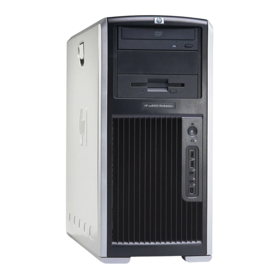
Product overview This chapter presents an overview of the hardware components of the HP Workstation. ● Product features on page 1 ● Product specifications on page 5 ● Energy Star on page 11 Product features Exploded view The following image shows a typical HP xw8400 Workstation. Drive configurations can vary. For complete and current information on supported accessories and components, see http://partsurfer.hp.com. - Page 12 Table 1-1 Exploded view (continued) Item Description Item Description Access panel Diskette drive System board PCI card Chassis Hard drive Front bezel * A CD-ROM is an example of an optical drive. Chapter 1 Product overview ENWW...
-
Page 13: Front Panel Components
Front panel components The following image shows a typical HP xw8400 Workstation. Drive configurations can vary. Figure 1-2 Front panel components Table 1-2 Front panel components Item Symbol Description Item Symbol Description Optical drive Headphone connector 5.25-inch drive bay USB 2.0 ports Diskette drive (optional) Hard drive activity light IEEE-1394a connector... -
Page 14: Rear Panel Components
Rear panel components Figure 1-3 Rear panel components Table 1-3 Rear panel components Item Symbol Description Item Symbol Description Power cord connector Graphics adapter Built In Self Test (BIST) LED Audio line-in connector Keyboard connector RJ-45 network connector Serial connector Parallel connector USB 2.0 ports Mouse connector... -
Page 15: Product Specifications
the side panel of the unit and on the rear panel. Keep the serial number available when contacting customer service for assistance. Figure 1-4 Serial number and COA label location Product specifications The following table lists the physical dimensions. Table 1-4 Physical characteristics Weight (depending on 18 - 25.2 kg (39.6 - 55.6 lb.) -
Page 16: Power Supply Specifications
Table 1-5 Voltage specification (continued) Voltage Minimum Maximum Description 12 V-G 11.52 V 12.6 V Used with PCI Express x16 auxiliary connector V12N –11.4 V –12.6 V Used by PCI 5 VSB 4.85 V 5.25 V Used for sleep circuitry Table 1-6 Current specification Current... -
Page 17: Power Consumption And Cooling
Table 1-7 Power supply specifications (continued) Rated voltage range 100–240 VAC 118 VAC Rated line frequency 50–60 Hz 400 Hz Operating line frequency range 47–66 Hz 393–407 Hz Rated input current 13.2 A@100–120 VAC 11.2 A@118 VAC 6.6 A@200–240 VAC Maximum rated power 800 W Heat dissipation... - Page 18 Table 1-8 Example 1 energy consumption (continued) Off (S5) 2.4 W 1.3 W 3.0 W 1.8 W 2.4 W 1.2 W * Energy Star low energy mode. This product is in compliance with US executive order 13221, WOL (wake on LAN) disabled Table 1-9 Example 1 Heat dissipation** 115 VAC...
-
Page 19: System Fans And Airflow
Table 1-10 Example 2 energy consumption (continued) Sleep (S3)* 7.4 W 5.7 W 8.1 W 6.8 W 6.9 W 6.0 W Off (S5) 2.4 W 1.3 W 3.0 W 1.8 W 2.4 W 1.2 W * Energy Star low energy mode. This product is in compliance with US executive order 13221, WOL (wake on LAN) disabled. -
Page 20: Power Cord Requirements
Power cord requirements The power cord set (flexible cord or wall plug) received with this product meets the requirements for use in the country where you purchased the equipment. If you must obtain a power cord for a different country, you should purchase a power cord that is approved for use in that country. -
Page 21: Pci Card Slot Power Specification
PCI card slot power specification Table 1-12 PCI and PCI Express slot power specifications Slot# Slot Type Slot Power (Maximum) PCI (32–bit, 33 MHz) 25 W* PCI Express x16 graphics 150 W** PCI Express x8 (x4) 25 W* PCI Express x16 (x4) 25 W* PCI-X 133 25 W*... - Page 22 EPA created the Energy Star Computers Program to promote energy efficiency and reduce air pollution through more energy-efficient equipment in homes, offices, and factories. HP products achieve this result by reducing the power consumption when not being used. Energy Star on HP workstations uses Advanced Configuration and Power Interface (ACPI) power management.
-
Page 23: Installing Or Restoring The Operating System
Installing or restoring the operating system This chapter describes the installation and restoration of the operating system. ● Installing the operating system and software on page 13 ● HP software on page 15 ● Restoring the Windows XP operating system on page 17 ●... -
Page 24: Installing Or Upgrading Device Drivers
Installing or upgrading device drivers To install hardware devices after the operating system installation is completed, the appropriate device drivers must be available. In addition, for optimum performance, your operating system must have the most recent updates, patches, and software fixes. Access the following resources for driver and software updates: ●... -
Page 25: Verifying Hardware Compatibility
Verifying hardware compatibility To determine which Linux versions have been verified to work on HP workstation hardware: Go to http://www.hp.com/support/linux_hardware_matrix. Select your HP workstation model. Installing the Linux operating system To install the Linux operating system on your Linux-enabled system, follow the instructions for Restoring the Linux operating system on page 19 in this chapter. -
Page 26: Restoring The Windows Vista™ Operating System
Restoring the Windows Vista™ operating system Your workstation has a several methods to restore your Windows Vista operating system to a near- factory state, or to the state of the system at a predefined restore point. Your system has a recovery partition on the system hard drive that contains software and data required for the restore process as described in the following sections. -
Page 27: Ordering Backup Software
deleted, the user partition is extended to reclaim the unused space, and the F11 boot prompt is removed. Emergency recovery as well as data backup and recovery is not possible after the application is uninstalled. CAUTION: Deleting the recovery partition or uninstalling the HP Backup and Recovery Manager application reduces or eliminates the ability to recover the system. -
Page 28: Restoring From Restoreplus! On The Recovery Partition
Restoring from RestorePlus! on the Recovery Partition Follow these steps to start the RestorePlus! process from the Emergency Recovery menu: Boot the workstation. Press the key when prompted during the boot process to enter the Emergency Recovery menu. The F11 prompt appears briefly during the boot process. Select Recover PC’s factory installed operating system, drivers, utilities, and applications from the Emergency Recovery menu. -
Page 29: Ordering Backup Software
CAUTION: Deleting the recovery partition or uninstalling the HP Backup and Recovery Manager application reduces or eliminates the ability to recover the system. Ordering backup software If you are unable to create system recovery CDs or DVDs, the HP Restore Plus CD set can be obtained through product support on http://www.hp.com/support. -
Page 30: Protecting The Software
Protecting the software To protect software from loss or damage, keep a backup copy of all system software, applications, and related files stored on the hard drive. See the operating system or backup utility documentation for instructions on making backup copies of data files. Chapter 2 Installing or restoring the operating system ENWW... -
Page 31: System Management
System management This section describes the various tools and utilities that allow for the system management of the workstation. ● Computer Setup (F10) Utility on page 21 ● Desktop management on page 31 Computer Setup (F10) Utility The Computer Setup (F10) Utility enables you to: ●... -
Page 32: Bios Rom
● Enable power-on password prompting during system restarts (warm boots) and during power-on. ● Secure the integrated I/O functionality, including the serial, USB, or parallel ports, audio, or embedded NIC, so that the I/O functionality cannot be used until they are unsecured. ●... -
Page 33: Computer Setup (F10) Utility Menu
Select your language from the list, and press the Enter key. In the Computer Setup (F10) Utility menu, five headings are displayed: File, Storage, Security, Power, and Advanced. Use the left and right arrow keys to select the appropriate heading. Use the up and down arrow keys to select the option you want, and press Enter. - Page 34 Table 3-1 Computer Setup (F10) Utility menu descriptions (continued) Heading Option Description Ignore Exits the Computer Setup (F10) Utility without applying or saving any changes. Changes and Exit Save Changes Saves changes to system configuration and exits the Computer Setup (F10) Utility. and Exit Storage Device...
- Page 35 Table 3-1 Computer Setup (F10) Utility menu descriptions (continued) Heading Option Description Enables and disables ability to write data to legacy media. BIOS DMA Data Transfers Determine the point where BIOS enables DMA transfers for both IDE and SATA devices when possible during POST to increase transfer speed.
- Page 36 Table 3-1 Computer Setup (F10) Utility menu descriptions (continued) Heading Option Description NOTE: If the setup password is set, you must enter Computer Setup (F10) Utility to change it, flash the ROM, and make changes to certain plug-and-play settings under Windows. Power-On Enables you to set and enable the power-on password.
- Page 37 Table 3-1 Computer Setup (F10) Utility menu descriptions (continued) Heading Option Description Network Enables a Network Service Boot which boots using the NIC PXE option ROM. In this case, the Service Boot actual boot image resides on a remote server. When enabled, you can set the boot order of the NIC PXE option ROM and you can force a network boot by pressing F12 during POST.
- Page 38 Table 3-1 Computer Setup (F10) Utility menu descriptions (continued) Heading Option Description Allows the PS2 mouse to wake from ACPI S3. PS2 keyboards are always enabled. (Disabling this option means that nudging the mouse will not trigger a system wake.) USB Wake on Device Insertion Enables the USB controllers to generate a wake event when a device is plugged in while the system is in an ACPI sleep state.
- Page 39 Table 3-1 Computer Setup (F10) Utility menu descriptions (continued) Heading Option Description When enabled, displays F10=Setup during POST. Disabling this feature prevents the text from being displayed but pressing F10 still accesses the Setup screen. F12 prompt (enable/disable) When enabled, displays F12=Network Service Boot during POST. Disabling this feature prevents the text from being displayed, but pressing F12 still forces the system to attempt booting from the network.
- Page 40 Table 3-1 Computer Setup (F10) Utility menu descriptions (continued) Heading Option Description PCI VGA This menu lets you select which device to use as the primary VGA device—the one that will show Configuration graphics during POST and boot, before the OS takes over graphics. The menu is dynamically generated based on detected VGA-compatible devices.
-
Page 41: Desktop Management
Table 3-1 Computer Setup (F10) Utility menu descriptions (continued) Heading Option Description Enables you to allow peer-to-peer memory reads between the PCI-X buses behind the PXH-V. Fast Delayed Transaction Timer Enables you to set Discard Transaction Timer to “short delay.” This may improve performance issues with certain PCI devices. -
Page 42: Remote System Installation
You might prefer to replace the preinstalled software image with a customized set of system and application software. There are several methods for deploying a customized software image, including: ● Installing additional software applications after unbundling the preinstalled software image. ●... -
Page 43: Altiris Client Management Solutions
● Remote changing of boot order ● Configuring the system BIOS settings For more information on the HP Client Manager, see http://h18000.www1.hp.com/im/prodinfo.html. Altiris Client Management solutions HP and Altiris have partnered to provide comprehensive, tightly integrated systems management solutions to reduce the cost of owning HP client PCs. HP Client Manager Software is the foundation for additional Altiris Client Management Solutions that address: ●... -
Page 44: Proactive Change Notification
Proactive Change Notification The Proactive Change Notification program uses the Subscriber's Choice website to proactively and automatically send you: ● Proactive Change Notification (PCN) emails informing you of hardware and software changes to most commercial workstations and servers, up to 60 days in advance. ●... -
Page 45: Failsafe Boot Block Rom
FailSafe Boot Block ROM The FailSafe Boot Block ROM allows for system recovery in the unlikely event of a ROM flash failure, for example, if a power failure occurs during a ROM upgrade. The Boot Block is a flash-protected section of the ROM that checks for a valid system ROM flash when the system is powered on. -
Page 46: Replicating The Setup
Replicating the setup The following procedures enable you to easily copy one setup configuration to other workstations of the same model to provide faster, more consistent configuration of multiple workstations. NOTE: Both procedures require a diskette drive or a USB device such as an HP DriveKey. To collect and replicate BIOS settings on multiple computers, use System Software Manager or HP Client Manager Software. -
Page 47: Dual-State Power Button
As soon as the workstation is powered on, press and hold the key until you enter the Computer Setup (F10) Utility. Press Enter to bypass the title screen, if necessary. NOTE: If you do not press the F10 key at the appropriate time, you must restart the workstation and press and hold the key again to access the utility. -
Page 48: Building Blocks And Partners
device drivers, utilities, and flashable ROM images needed to run the latest Microsoft Windows operating system on the HP workstation. Building blocks and partners HP management solutions integrate with other systems management applications, and are based on industry standards, such as: ●... -
Page 49: Password Security
Table 3-3 Security features overview (continued) Feature Purpose How It Is Established Power-On Password Prevents use of the workstation until the From the Computer Setup (F10) password is entered. This can apply to both Utility menu. initial system startup and restarts. Setup Password Prevents reconfiguration of the workstation From the Computer Setup (F10) -
Page 50: Establishing A Power-On Password In The Computer Setup (F10) Utility
To establish a setup password using workstation setup: Power on or restart the workstation. In Windows, click Start>Turn off>Restart. As soon as the computer is powered on, press and hold until you enter the Computer Setup (F10) Utility. Press Enter to bypass the title screen, if necessary. -
Page 51: Entering A Setup Password
Entering a setup password If a setup password has been established on the workstation, you will be prompted to enter it each time you run the Computer Setup (F10) Utility. To enter a setup password: Power on or restart the workstation. In Windows, click Start>Shut Down>Restart the Computer. -
Page 52: Deleting A Power-On Or Setup Password
Deleting a power-on or setup password To delete a power-on or setup password: Power on or restart the workstation. In Windows, click Start>Shut Down>Restart the Computer. To delete the power-on password, go to step 3. To delete the setup password, as soon as the workstation is powered on, press and hold the key until you enter the Computer Setup (F10) Utility. -
Page 53: Hood Sensor (Smart Cover Sensor)
Hood sensor (Smart Cover Sensor) The optional hood sensor is a combination of hardware and software technology that can alert you when the workstation side access panel has been removed. There are three levels of protection, as described in the following table. Table 3-5 Hood sensor protection levels* Level... -
Page 54: Fault Notification And Recovery
Fault notification and recovery Fault notification and recovery features combine innovative hardware and software technology to prevent the loss of critical data and minimize unplanned downtime. If the workstation is connected to a network managed by HP Client Manager software, the computer sends a fault notice to the network management application. -
Page 55: Removal And Replacement Procedures
Removal and replacement procedures This chapter describes removal and replacement procedures of most internal components. ● Observe warnings and cautions on page 45 ● Service considerations on page 46 ● Customer Self Repair on page 50 ● Pre-disassembly procedures on page 50 ●... -
Page 56: Service Considerations
CAUTION: Observe the following cautions when removing or replacing a processor: — Installing a processor incorrectly can damage the system board. Have an HP authorized reseller or service provider install the processor. If you plan to install it yourself, read all of the instructions carefully before you begin. -
Page 57: Generating Static
Generating static The following table shows that Different activities generate different amounts of static electricity. Static electricity increases as humidity decreases. Table 4-1 Static electricity Relative Humidity Event Walking across carpet 7,500 V 15,000 V 35,000 V Walking across vinyl floor 3,000 V 5,000 V 12,000 V... -
Page 58: Grounding The Work Area
Table 4-2 Static shielding protection levels (continued) Method Voltage Carbon-loaded plastic 7,500 Metallized laminate 15,000 Grounding the work area To prevent static damage at the work area: ● Cover the work surface with approved static-dissipative material. Provide a wrist strap connected to the work surface and properly grounded tools and equipment. -
Page 59: Required Tools And Software
Required tools and software The following tools and software are required to service your workstation: ● Torx T-15 screwdriver or flathead screwdriver ● Diagnostics software Screws The screws used in the workstation are not interchangeable. They might have standard or metric threads and might be of different lengths. -
Page 60: Customer Self Repair
WARNING! This workstation contains a lithium battery. A risk of fire and chemical burn exists if the battery is handled improperly. Do not disassemble, crush, puncture, short external contacts, dispose of in water or fire, or expose it to temperatures higher than 140 degrees F (60 degrees C). NOTE: Batteries, battery packs, and accumulators should not be disposed of with general household waste. -
Page 61: System Board Components
System board components The following image shows the system board connectors and sockets on the HP xw8400 Workstation. Figure 4-1 System board identification Table 4-3 System board components Item Description Item Description Item Description Item Description Memory Fan PCI (32-bit, 33 MHz) PCI-X 100 Processor 2 Fan PS/2 Keyboard/... -
Page 62: System Board Architecture
Table 4-3 System board components (continued) Item Description Item Description Item Description Item Description ** The PCI Express x8 is a PCI Express x8 connector that has x4 bandwidth. System board architecture The following image shows the HP xw8400 Workstation block diagram. Figure 4-2 System board block diagram Removing and replacing components... - Page 63 NOTE: Prior to removing and replacing a component, make sure you remove all installed components that obstruct or prevent the removal of the component. If you are unsure how to remove a particular component, please do one of the following: 1.
-
Page 64: Disassembly Order
Disassembly order Use the following table to determine the sequence in which to remove the major components. Pre-disassembly ( Pre- disassembly procedures on page Locks (Removing the security lock (optional) on page Access panel (Access panel on page Hood sensor (Hood sensor (Smart Cover Sensor) on page... -
Page 65: Removing The Security Lock (Optional)
CPU heatsink (Removing the CPU heatsink on page Processor (Removing the processor on page PCI retainer (PCI retainer on page PCI retention clamp (PCI retention clamp on page PCI or PCI Express card (Removing PCI or PCI Express cards on page CPU heatsink (Removing the CPU heatsink on page... -
Page 66: Removing The Cable Lock (Optional)
Removing the cable lock (optional) If a cable lock is installed, remove it before servicing the unit. To remove the cable lock, unlock it and pull it out of the cable lock slot as shown in the following image. Figure 4-4 Removing the cable lock Universal chassis clamp lock (optional) If a universal chassis clamp lock is installed, remove it before servicing the unit. -
Page 67: Access Panel
Remove the screw attaching the lock to the chassis. Figure 4-6 Remove fastening screw Access panel Before accessing the internal components of the workstation, the access panel must be removed. To remove the access panel: WARNING! Before removing the workstation access panel, ensure that the workstation is powered off and that the power cord is disconnected from the electrical outlet. -
Page 68: Front Bezel
To replace the access panel, align the bottom groove of the side panel with the bottom edge of the chassis. Rotate the side panel toward the chassis and press firmly until the latch engages. Front bezel To remove the front bezel: Lift up on the three (1) tabs located on the front bezel. -
Page 69: Bezel Blanks
Bezel blanks To remove the bezel blanks: Disconnect power from the system ( Pre-disassembly procedures on page 50) and remove the front bezel (Front bezel on page Remove the bezel blanks by squeezing in on the tabs (1) and pushing the bezel blanks out (2). Figure 4-9 Removing the bezel blanks Hood sensor (Smart Cover Sensor) -
Page 70: Front Panel I/O Device Assembly
Slide the hood sensor forward. Push the hood sensor down and remove it from the chassis. Figure 4-10 Removing the hood sensor To replace the hood sensor, reverse the previous steps. Front panel I/O device assembly To remove the front panel I/O device assembly: Disconnect power from the system ( Pre-disassembly procedures on page 50). -
Page 71: Power Button Assembly And System Speaker
Pull the bracket away from the front panel I/O device assembly. Figure 4-11 Removing the front panel I/O device assembly Slide the front panel cables through the chassis and out the front of the unit. To replace the front panel I/O device assembly, reverse the previous steps. Power button assembly and system speaker The power button and the system speaker are part of the same assembly. -
Page 72: Power Supply
Slide the speaker away from the three flanges and remove it from the chassis. Figure 4-12 Removing the speaker Power supply Disconnect power from the system ( Pre-disassembly procedures on page 50), and remove the access panel (Access panel on page 57). -
Page 73: System/Memory Fan Assembly
Remove the four screws (1) from the back panel. Slide the power supply toward the front, and lift up (2) to remove it from the chassis. Figure 4-13 Removing the power supply To install the power supply, reverse the previous steps. System/memory fan assembly The system fan and memory fan are connected and treated as a unit. -
Page 74: Memory
Press down on the ribbed portion of the system fan housing (4), rotate the fan housing down, and lift the unit out of the chassis. Figure 4-14 Removing the system/memory fan assembly To replace a system/memory fan assembly, reverse the previous steps. CAUTION: When installing the system/memory fan assembly, ensure that the fan is situated so that the airflow direction is going out of the chassis to avoid overheating. -
Page 75: Removing Memory Module
Removing memory module Disconnect power from the system ( Pre-disassembly procedures on page 50), and remove the access panel (Access panel on page 57). Place the workstation on its side with the system board facing up. CAUTION: To ensure that memory modules are not damaged during removal or installation, power off the workstation and unplug the power cord from the AC power outlet. -
Page 76: Installing Memory Module
Lift the DIMM straight up, and remove it from the unit. Figure 4-16 Removing DIMM NOTE: DIMMs and DIMM sockets are keyed for proper installation. Ensure that these guides align when installing a DIMM. Installing memory module CAUTION: HP only ships DIMMs that are electrically and thermally compatible with this product. Because third-party DIMMs might not be electrically or thermally compatible, they are not supported by You must load memory modules in valid configurations: ●... -
Page 77: Installing A Dimm
● Load the memory module pairs in order of size, from smallest to largest. Figure 4-17 Identifying memory slots The BIOS generates warnings/errors on invalid memory configurations. ● If there is no way to obtain a valid memory configuration by disabling some of the plugged-in memory, the BIOS will halt with a diagnostics 2006 code for memory error (five beeps and blinks). -
Page 78: Pci Slots
Gently push out on the socket levers. Lower the DIMM straight down, and ensure the socket levers secure the module into place. Lower the memory fan until it snaps into place. NOTE: Ensure that all cables are clear of the fan housing when lowering the memory fan. PCI slots Figure 4-19 Identifying PCI slots... -
Page 79: Installing The Pci Retainer
For short or tall cards, lift the PCI retainer arm (1) with one hand, press in on the sides (2) of the retainer, and rotate it (3) out of the chassis. Figure 4-20 Removing the short or tall card PCI retainer Installing the PCI retainer Disconnect power from the system ( Pre-disassembly procedures on page... -
Page 80: Pci Retention Clamp
PCI retention clamp Disconnect power from the system ( Pre-disassembly procedures on page 50), and remove the access panel (Access panel on page 57). Place the workstation on its side with the system board facing up. Open the PCI retention clamp by pressing down on the two green clips at the ends of the clamp and rotating the clamp toward the back of the system. -
Page 81: Removing Pci Or Pci Express Cards
Table 4-5 PCI Express compatibility matrix for xw8400 Slot 2 Slot 3 Slot 4 x16 mechanical x8 mechanical x16 mechanical x16 electrical x4 electrical x4 electrical PCI Express x1 Card PCI Express x4 Card PCI Express x8 Card PCI Express x16 Card Removing PCI or PCI Express cards Disconnect power from the system (... -
Page 82: Pci Or Pci Express Installation
PCI or PCI Express installation Disconnect power from the system ( Pre-disassembly procedures on page 50), and remove the access panel (Access panel on page 57). Place the workstation on its side with the system board facing up, and remove the PCI retainer(PCI retention clamp on page 70). -
Page 83: Memory Riser Assembly
Memory riser assembly This section describes how to remove and install a memory riser assembly. Removing a memory riser assembly The following steps describe how to remove a memory riser assembly. Disconnect memory riser cable P93 from the memory fan cable. Figure 4-25 Disconnect memory riser cable P93 from memory fan cable Remove the memory fan/duct assembly. - Page 84 Disconnect the memory riser power cable. Disconnect each memory card power cable from the power connector on a memory card. Figure 4-27 Disconnect riser card power cable Remove the memory riser cards from the card cage by grasping each card at its corners and pulling straight up.
- Page 85 Lift the memory riser card guide. Figure 4-29 Remove riser card guide Disconnect memory riser cable P17 from power supply cable P17. Figure 4-30 Disconnect memory cable P17 from power supply cable P17 ENWW Removing and replacing components...
-
Page 86: Installing A Memory Riser Assembly
Disconnect memory riser cable P92 from the system board. Figure 4-31 Disconnect memory riser cable P92 from system board Installing a memory riser assembly The following steps describe how to install a memory riser card. Connect memory riser cable P92 into the memory riser connector on the system board. Figure 4-32 Connect memory riser cable P92 to system board Chapter 4 Removal and replacement procedures... - Page 87 Connect memory riser cable P17 to power supply cable P17. Figure 4-33 Connect memory riser cable P17 to power supply cable P17 Open all memory slot latches. Use a small screwdriver for convenience. Figure 4-34 Open memory slot latches ENWW Removing and replacing components...
- Page 88 Install the memory riser card guide into memory slots 2, 4, 6, and 8 in the workstation chassis. Align the cards guide and press it securely into the slots. Figure 4-35 Install riser card guide Install the memory DIMMs in the memory riser cards. Figure 4-36 Install DIMMs Chapter 4 Removal and replacement procedures...
- Page 89 Install the loaded memory riser cards in the riser card cage. Figure 4-37 Install memory riser cards in card cage Install the memory riser card power cable. Connect each memory card power cable connector into the power connector on a memory card. Figure 4-38 Install riser card power cable ENWW...
- Page 90 Insert the memory riser card power cable into the notch on the riser card guide. Figure 4-39 Insert riser card cable into card guide notch Install the memory fan/duct assembly. Place the rear of the assembly under the chassis lip and lower it into the chassis.
-
Page 91: Front Fan Removal (Optional)
Connect memory riser cable P93 to the memory fan cable. Figure 4-41 Connect memory riser cable P93 to memory fan cable Front fan removal (Optional) To remove the front fan: Disconnect power from the system ( Pre-disassembly procedures on page 50), and remove the access panel (Access panel on page... - Page 92 Remove the fan from the card guide by applying outward pressure on the card guide while lifting the fan away. Figure 4-43 Removing the fan from the card guide To install the front fan: Place the fan in the card guide with the fan label facing into the card guide, and the fan protector screen facing outward.
-
Page 93: Battery
Battery CAUTION: Before removing the battery, ensure your CMOS settings are backed up because all CMOS settings are lost when the battery is removed. To back up the CMOS settings, use Computer Setup and run the Save to Diskette option from the File menu. Disconnect power from the system ( Pre-disassembly procedures on page 50), and remove the... -
Page 94: Power Connections To Drives
Power connections to drives For help in identifying power cables, refer to the following figure and table. Route or tie cables so that they cannot interfere with the CPU heatsink fans. Figure 4-46 Identifying correct power connections Table 4-6 Power connector descriptions Connector Description 24–pin power connector... - Page 95 Disconnect the data (1), power (2) and audio (3) cables from the drive. The connector colors might be different than illustrated. NOTE: The audio cable is only required for Linux-based systems. Figure 4-47 Disconnecting the IDE (left) or SATA (right) cable from the optical drive Lift the green drivelock release lever, and gently slide the drive out of the chassis.
-
Page 96: Replacing The Sata Optical Drive Data Cable
If you are installing more than one optical drive, route the cable as in the following image. NOTE: The data cable for IDE optical drives is routed under the system board. Figure 4-49 Connecting IDE (left) or SATA (right) optical drive cable to system board Replacing the SATA optical drive data cable If your workstation has a SATA optical drive, replace the cable as follows: Disconnect power from the system (... -
Page 97: Diskette Drive (Optional)
Diskette drive (optional) To remove a diskette drive: Disconnect power from the system ( Pre-disassembly procedures on page 50). Remove the access panel (Access panel on page 57) and the front bezel (Front bezel on page 58). Disconnect the cables from the back of the diskette drive. Figure 4-51 Disconnecting cables from the diskette drive While lifting the green drivelock release tab, slide the drive forward out of the chassis. - Page 98 Remove the diskette drive from its bracket by removing the two M3 screws in the rear-most holes and pulling the diskette drive from the bracket. Figure 4-53 Removing the diskette drive from the bracket To replace a diskette drive: Slide the diskette drive into the bracket, and secure it with two M3 screws. While lifting the green drivelock release tab, slide the drive forward into the chassis.
-
Page 99: Hard Drive
Route the diskette drive data cable between the system board and the hard drive cage. Your cable might look different than the one shown. CAUTION: The cable must stay between the system board and the hard drive cage. It might be necessary to push the cable down so that it catches on the system board. -
Page 100: Installing A Hard Drive
Push in on the green drivelock release tabs, and pull the hard drive out of the chassis. Figure 4-55 Removing the hard drive Installing a hard drive Select a drive bay in which to install the drive. If installing more than one hard drive, use the hard drive order shown in the following image. - Page 101 Attach the rails to the hard drive. Align the pins on the rails with the hard drive holes, and snap the rails into place. Figure 4-57 Attaching rails to the hard drive Push the drive into the selected bay until it snaps into place. Attach a data cable from a SATA connector on the system board to the hard drive, and attach a power cable to the drive.
-
Page 102: Installing A Hard Drive In The Fifth Hard Drive Bay
For a SAS hard drive, attach a SAS/SATA adapter to the connector on the hard drive. Attach a data cable from a SAS connector on the system board to the hard drive, and attach a power cable to the drive. Figure 4-59 Installing the SAS/SATA adapter (left) and cable (right) Installing a hard drive In the fifth hard drive bay... -
Page 103: Processor Heatsink
Attach a data cable from a SATA connector on the system board to the hard drive, and attach the fifth drive power cable to the drive. Figure 4-61 Attaching the data cable for the SATA hard drive in the fifth hard drive bay For a SAS hard drive, attach a SAS/SATA adapter to the connector on the hard drive. - Page 104 Remove the four processor screws slowly, being sure to loosen all the screws evenly. Loosen one pair of diagonally opposite screws (1) until the screw shanks disengage from the system board, and then loosen the remaining pair (2). Do not fully loosen one screw, then move on to the next. Loosen all of the screws a little at a time, so that the processor remains level.
-
Page 105: Replacing The Cpu Heatsink
Replacing the CPU heatsink Disconnect power from the system ( Pre-disassembly procedures on page 50). Remove the access panel (Access panel on page 57) and the CPU heatsink (Removing the CPU heatsink on page 93). Use alcohol and a soft cloth to clean all of the thermal interface material residue from the CPU heatsink and processor. -
Page 106: Processor
Insert and tighten the four CPU heatsink screws. First, tighten all of the screws partially so that the CPU heatsink remains level. Next, fully tighten one pair of diagonally opposite screws (1), and then fully tighten the remaining pair (2). Tighten firmly to a torque setting of 6 in-lb. Figure 4-65 Identifying proper screw fastening order Connect the CPU heatsink fan connector to the system board (2) as shown in Figure 4–45. - Page 107 Raise the processor socket handle (1) fully (the full swing angle of the lever is approximately 105 degrees). Lift the processor socket cover (2). Figure 4-66 Raising the processor socket handle Lift the processor straight out of the socket. Figure 4-67 Lifting the processor from the socket CAUTION: To avoid bending the socket pins, keep the processor perfectly flat when removing or...
-
Page 108: Replacing The Processor
Replacing the processor Disconnect power from the system ( Pre-disassembly procedures on page 50). Remove the access panel (Access panel on page 57), the CPU heatsink (Removing the CPU heatsink on page 93), and the processor (Removing the processor on page 96). -
Page 109: Replacing The System Board
Lift the system board out (2) of the chassis, being careful not to damage the cables and rear panel connectors. You can lift the board by the rear audio connector and the 2 x 4 power connector. Figure 4-69 Removing the system board Replacing the System Board: Insert the system board straight down, and ensure that all system board standoffs engage with the keyholes in the chassis. - Page 110 100 Chapter 4 Removal and replacement procedures ENWW...
-
Page 111: E-Support
System diagnostics and troubleshooting This chapter discusses the tools available for diagnosing and troubleshooting system issues. ● E-Support on page 101 ● Troubleshooting checklist on page 102 ● LED color definitions on page 102 ● HP Insight Diagnostics Offline Edition on page 102 ●... -
Page 112: Troubleshooting Checklist
Troubleshooting checklist Before running any of the diagnostic utilities, use the following checklist to find possible solutions for workstation or software problems. ● Are the workstation and monitor connected to a working electrical outlet? ● Is the workstation powered on? ●... -
Page 113: Key Features And Benefits
Key features and benefits HP Insight Diagnostics simplifies the process of effectively identifying, diagnosing, and isolating the hardware issues. In addition to robust management tools, service tools can be invaluable in quickly resolving system problems. To streamline the service process and resolve problems quickly, you must have the right information available at the time you place a service call. -
Page 114: Download The Iso Image
Download the ISO image Browse to http://www.hp.com. Click Software & Driver Downloads. Enter your product number (for example, xw8400) in the text box, and press the Enter key. Select your operating system. Click the Diagnostic link. Locate HP Insight Diagnostics Offline on the display, and click Download. User interface Navigation The Insight Diagnostics home page contains the following tabs: Survey, Test, Status, Log, and... -
Page 115: Status Tab
Quick Test—Provides a predetermined script in which a sample of most hardware components is exercised and requires no user intervention. Complete Test—Provides a predetermined script in which most hardware components are fully tested. You can select Interactive or Unattended tests, which will change the devices tested during the Complete Test. -
Page 116: Log Tab
● Individual test times ● Condition status of each test Log tab The Log tab consists of two views: Test Log—Displays all tests that have been executed, the number of times the test executed, the number of times the test failed, and the time it took to complete the test. Clicking the Clear Test Log button clears the contents of the Test Log. - Page 117 Table 5-2 Diagnostic LED codes Chassis Indicator LEDs Power LED and Sound Diagnosis and Service Action Activity None CAUTION: Disconnect AC power from the workstation before reseating or replacing components because there is power to the system board even when the workstation is powered down.
- Page 118 Table 5-2 Diagnostic LED codes (continued) Chassis Indicator LEDs Power LED and Sound Diagnosis and Service Action Activity Power supply failure. Open the access panel and ensure the following connections are secure on the system board: ◦ 24–pin main power (all systems) ◦...
-
Page 119: Troubleshooting Scenarios And Solutions
Table 5-2 Diagnostic LED codes (continued) Chassis Indicator LEDs Power LED and Sound Diagnosis and Service Action Activity System board failure (ROM detected failure before video). Clear CMOS. Replace system board. Blinks red 8 times, once per CAUTION: Disconnect AC power from the workstation before reseating or replacing second, then 2 second pause, components because there is power to the system board even when the workstation is powered 8 beeps... - Page 120 Table 5-3 Minor problems (continued) Problem Cause Possible Solution Poor performance is Processor is hot. Be sure airflow to the workstation is not blocked. experienced. Be sure the fans are connected and working properly (some fans only operate when needed). Be sure the CPU heatsink is installed properly.
-
Page 121: Solving Power Supply Problems
Table 5-3 Minor problems (continued) Problem Cause Possible Solution ● If the power supply fan spins and the BIST* LED lights, then the power supply is good. Replace the system board. ● If the power supply fan does not spin or the BIST* LED does not light, replace the power supply. -
Page 122: Solving Diskette Problems
Table 5-4 Power supply problems (continued) Problem Cause Solution Workstation powered off Processor thermal protection CAUTION: Disconnect AC power from the workstation automatically and the Power LED activated. before reseating or replacing components because there flashes red two times, once every is power to the system board even when the workstation A fan might be blocked or not second, followed by a two-second... - Page 123 Table 5-5 Diskette problems (continued) Problem Cause Solution Drive not found. Cable is loose. Reseat diskette drive data and power cables. Removable drive is not seated Reseat the drive. properly. Diskette drive cannot write to a Diskette is not formatted. Format the diskette.
-
Page 124: Solving Hard Drive Problems
Solving hard drive problems Table 5-6 Hard drive problems Problem Cause Solution Hard drive error occurs. Hard disk has bad sectors or Use a utility to locate and block usage of bad sectors. If has failed. necessary, reformat the hard disk. Disk transaction problem. - Page 125 Table 5-7 Display problems (continued) Problem Cause Solution The monitor is off. Switch the monitor to on (LED is on). You might need to refer to the monitor manual for an explanation of the LED signals. Screen blanking utility installed Press any key or click the mouse button and, if set, enter or energy saver features your password.
-
Page 126: Solving Audio Problems
Table 5-7 Display problems (continued) Problem Cause Solution Monitor is not capable of Change requested resolution. displaying requested resolution. The picture is broken up, rolls, The monitor connections might Be sure the monitor cable is securely connected to the jitters, or flashes. be incomplete or the monitor workstation. -
Page 127: Solving Printer Problems
Table 5-8 Audio problems (continued) Problem Cause Solution Digital CD audio is Enable digital CD audio: not enabled. From the Control Panel, select System. On the Hardware tab, click Device Manager. Right-click the CD/DVD device and select Properties. On the Properties tab, be sure Enable digital CD audio for this CD-ROM device is selected. -
Page 128: Solving Keyboard And Mouse Problems
Table 5-9 Printer problems (continued) Problem Cause Solution where [printer port] is the address of the printer being used. If the printer works, reload the printer driver. If you are on a network, you Make the proper network connections to the printer. might not have made the connection to the printer. -
Page 129: Solving Front Panel Component Problems
Table 5-10 Keyboard and mouse problems (continued) Problem Cause Solution Workstation is Stand By mode. Press the power button to resume from Stand By mode. Mouse will only move vertically or Mouse roller ball is dirty. Remove roller ball cover from the bottom of the mouse and horizontally, or movement is jerky. - Page 130 Table 5-12 Hardware installation problems Problem Cause Solution A new device is not recognized as Device is not seated or Be sure that the device is properly and securely connected part of the system. connected properly. and that pins in the connector are not bent. Cables of new external device Be sure that all cables are properly and securely connected are loose or power cables are...
-
Page 131: Solving Network Problems
Solving network problems These guidelines do not discuss the process of debugging the network cabling. Table 5-13 Network problems Problem Cause Solution Wake-on-LAN feature is not Wake-on-LAN is not enabled. Use the Network control application to enable Wake-on- functioning. LAN. Network driver does not detect Network controller is disabled. -
Page 132: Solving Memory Problems
Table 5-13 Network problems (continued) Problem Cause Solution The expansion board installed is a Under the Computer Setup Advanced menu, change the Network Interface Card (NIC) and resource settings for the board. conflicts with the embedded NIC. Network controller stops working The files containing the network Reinstall the network drivers, using the Restore Plus! CD. -
Page 133: Solving Processor Problems
Table 5-14 Memory problems (continued) Problem Cause Solution You have run out of memory Check the memory requirements for the application or add for the application. more memory to the workstation. Power LED flashes red 5 times, Memory is installed incorrectly CAUTION: Disconnect AC power from the workstation once every second, followed by a... -
Page 134: Solving Internet Access Problems
Table 5-16 CD-ROM and DVD problems (continued) Problem Cause Solution Cannot eject compact disc (tray- Disc not properly seated in the Power off the workstation, and insert a thin metal rod load unit). drive. into the emergency eject hole and push firmly. Slowly pull the tray out from the drive until the tray is fully extended, and remove the disc. -
Page 135: Advanced Error Reporting
Table 5-17 Internet access problems (continued) Problem Cause Solution Cookies are corrupted. Select Start>Control Panel. Double-click Internet Options. On the General tab, click Delete Cookies. Cannot automatically launch You must log on to the ISP Log on to the ISP and launch the desired program. Internet programs. -
Page 136: Error Classes
uncorrectable non-fatal errors are masked so they are logged, but will not generate an Err0. Unlike correctable non-fatal errors, the uncorrectable non-fatal errors will automatically force an F1 Boot prompt on the next reboot. Fatal errors are not masked. When errors are detected and not masked, they generate an Err0 signal. There are four ways to handle this type of error. -
Page 137: Post Error Messages
POST error messages POST is a program run at startup that initializes and runs some tests on installed hardware. An audible and/or visual message occurs if the POST encounters a problem. POST checks the following items to ensure that the workstation system is functioning properly: ●... - Page 138 Table 5-18 POST error messages (continued) Screen Message Probable Cause Recommended Action 163–Time and Date Not Set. Invalid time or date in configuration Set the date and time under Control Panel or in memory. F10 Setup, depending on the operating system. RTC (real-time clock) battery might If the problem persists, replace the RTC battery.
- Page 139 Table 5-18 POST error messages (continued) Screen Message Probable Cause Recommended Action 211–Memory warning An unknown issue with one of the CAUTION: Disconnect AC power from the condition detected. DIMMs has been detected. workstation before reseating or replacing components because there is power to the system board even when the workstation is powered down.
- Page 140 Table 5-18 POST error messages (continued) Screen Message Probable Cause Recommended Action 404–Parallel Port Address Both external and internal ports are Remove any parallel expansion cards. Conflict Detected. assigned to parallel port X. Clear CMOS. Reconfigure card resources and run Computer Setup (F10 Setup).
- Page 141 Table 5-18 POST error messages (continued) Screen Message Probable Cause Recommended Action 912–Computer Cover Has No action required. Been Removed Since Last System Start Up. 914–Hood Lock Coil is not Hood lock mechanism is missing or Reconnect or replace the hood locking Connected.
- Page 142 Table 5-18 POST error messages (continued) Screen Message Probable Cause Recommended Action 946-Correctable patrol data Bad DIMM or improperly installed CAUTION: Disconnect AC power from the ECC error DIMM workstation before reseating or replacing components because there is power to the system board even when the workstation is powered down.
- Page 143 Table 5-18 POST error messages (continued) Screen Message Probable Cause Recommended Action 961-Uncorrectable data ECC Bad DIMM or improperly installed CAUTION: Disconnect AC power from the on replay error DIMM workstation before reseating or replacing components because there is power to the system board even when the workstation is powered down.
- Page 144 Table 5-18 POST error messages (continued) Screen Message Probable Cause Recommended Action 1794–Inaccessible devices Devices attached to the SATA 1 (blue) Run Computer Setup (F10 Setup). attached to SATA 1 and/or and SATA 3 (black) connectors are Select Storage>Storage Options, and set the SATA 3.
-
Page 145: Appendix A Appendix A - Sas Devices
Appendix A — SAS devices Supported SAS RAID configurations The following RAID configurations are supported on the HP xw8400 Workstation. NOTE: This section does not apply to configuring RAID in the Linux environment. For RAID in the Linux environment, configure SW RAID configurations as provided by Red Hat Enterprise Linux. ●... -
Page 146: Sas Raid 1 (Im) Configuration
In the RAID Properties screen, use the arrow keys to select the first disk for the IS volume. Then use the arrow keys to move to the Array Disk column for this disk, and press the SPACE, +, or key to select Yes as the value for this column. If partitions are defined on the selected disk, a message appears warning you that data on the disk will be lost when the striped volume is created. -
Page 147: Sas Raid 1E (Ime) Configuration
SAS RAID 1E (IME) configuration Follow the steps below to configure an Integrated Mirroring Extended (IME) volume with the BIOS-based configuration utility. The configuration procedure assumes that the system already has the required disk and disk controllers. On the Main menu screen of the BIOS-based configuration utility, use the arrow keys to select an adapter. - Page 148 138 Appendix A Appendix A — SAS devices ENWW...
-
Page 149: Appendix B Appendix B - Sata Devices
Appendix B — SATA devices This appendix describes how to use the Intel® Matrix Storage Manager option ROM Configuration Utility to set up and manage SATA RAID volumes. NOTE: If only a single HDD is attached, the Intel Matrix Storage Manager option ROM will not execute, and no associated messages will be displayed. -
Page 150: Creating Raid Volumes
Press the left or right arrow key to select Enable. Press to accept the new setting. Press left arrow, right arrow, left arrow, and right arrow to highlight File>Save Changes and Exit, and press Enter. Press when prompted. Creating RAID volumes Use the Intel Matrix Storage Manager option ROM Configuration Utility to create RAID volumes. - Page 151 ● Use the up or down arrow key to highlight 4. Exit, and press Enter. ● Use the up or down arrow key to highlight 3. Reset Disks to Non-RAID, and press Enter. Press the up and down arrow keys and <Space> to mark individual physical disks to be reset. Press Enter to complete the selection.
- Page 152 142 Appendix B Appendix B — SATA devices ENWW...
-
Page 153: Appendix C Appendix C - Ultra Ata Devices
Appendix C — Ultra ATA devices Ultra ATA jumpers NOTE: This system supports a mixed configuration of UATA/IDE optical drives, and SAS and SATA hard drives. While HP supports the presence of SCSI and IDE hard drives, it does not ship any configurations using those drives. -
Page 154: Device Classes
For optimal performance of a workstation system, all drives must be attached to the ATA controllers in a specified sequence. This sequence is determined by the device class of the drives and by specific attach sequence rules. Device classes To determine the best drive attach sequence, ATA/ATAPI drives are segregated into four different classes based on the bandwidth demands they place on an ATA controller. -
Page 155: Attach Sequence Worksheet
Table C-2 General attach sequence rule (continued) Sequence Description If only three drives, attach the final drive here. If a fourth drive exists, attach the lowest class drive here. If there is a fourth drive, attach the final drive here—the drive with the highest class number of all devices. -
Page 156: Example 2: Four Device Installation Sample
Table C-4 Attach sequence worksheet—Three device installation (sample) (continued) Devicen ame Device class Position Controller name Device number number DVD drive Secondary CD-ROM drive Secondary Installing drive order (2) Example 2: Four device installation sample A system has four devices: Ultra ATA-100 hard drive, Ultra ATA-100 hard drive, DVD-CDR/W drive, and a ZIP-250 drive. -
Page 157: Additional Drive Application Notes
Installing drive order (3) Additional drive application notes ● When replacing a hard drive, the replacement should be of the same type (Ultra ATA-33, -66, or -100) as that being removed to retain the same level of performance. SMART The Self Monitoring Analysis and Recording Technology (SMART) ATA drives for HP workstations have built-in drive failure prediction that warns the user or network administrator of an impending failure or crash of the hard drive. - Page 158 148 Appendix C Appendix C — Ultra ATA devices ENWW...
-
Page 159: Appendix D Appendix D - Connector Pins
Appendix D — Connector pins Connector pin descriptions Ethernet connector Signal (+) Transmit Data (-) Transmit Data (+) Receive Data Unused Unused (-) Receive Data Unused Unused Parallel connector Signal Signal Signal Strobe Data Bit 5 Select Data Bit 0 Data Bit 6 Auto Linefeed Data Bit 1... - Page 160 Serial connector Signal Carrier Detect Receive Data Transmit Data Data Terminal Ready Signal Ground Data Set Ready Request to Send Clear to Send Ring Indicator USB connector Signal +5 VDC - Data + Data IEEE 1394 connector Signal power tpb- tpb+ tpa- tpa+...
- Page 161 Line-in audio connector (1/8 inch) Signal 1 (Tip) Audio_In_Left 2 (Ring) Audio_In_Right 3 (Shield) Ground Line-out audio connector (1/8 inch) Signal 1 (Tip) Audio_Out_Left 2 (Ring) Audio_Out_Right 3 (Shield) Ground SATA connector Signal Signal Signal Data Cable Power Cable Power Cable Ground 3.3-V power 5-V power...
- Page 162 SAS connector Segment Backplane receptacle Plug and cable receptacles Primary signal segment SIGNAL GROUND SIGNAL GROUND SIGNAL GROUND Secondary signal segment SIGNAL GROUND SIGNAL GROUND SIGNAL GROUND Power segment precharge GROUND GROUND GROUND precharge GROUND READY LED GROUND precharge 152 Appendix D Appendix D — Connector pins ENWW...
- Page 163 VGA connector Signal Signal Signal Red Analog Monitor ID Green Analog DDC Serial Data Blue Analog Horizontal Sync Monitor ID +5V DC Vertical Sync DDC Serial Clock DVI connector Signal Signal T.M.D.S DATA 2- HOT PLUG DETECT T.M.D.S DATA 2+ T.M.D.S DATA 0- T.M.D.S DATA 2/4 SHIELD T.M.D.S DATA 0+...
- Page 164 ATA/ATAPI (IDE) standard drive cable connector Signal Signal Signal Reset DMAK DD14 INTRQ DD15 IOCS16 (Key) PDIAG (cable detect) DMARQ DD10 DIOW CS1FX DD11 CS3FX DIOR DASP IORDY CSEL 24-Pin Main power connector +3.3 V -12 V +5 V +3.3 V +5 Vaux +5 V/+5 V-Rsense +12 V-B...
- Page 165 4-Pin power (memory system board) connector Color Signal BLK w/YEL stripe +12V-M BLK w/YEL stripe +12V-M 8-Pin power (for CPUs) Color Signal Gray +12 V CPU0 Rsense BLK w/WHT stripe +12 V CPU0 BLK w/WHT stripe +12VCPU0 BLK w/light blue +12VCPU1 stripe BLK w/light blue...
- Page 166 Keyboard connector Signal Data Unused Ground +5 VDC Clock Unused Mouse connector Signal Data Unused Ground +5 VDC Clock Unused 156 Appendix D Appendix D — Connector pins ENWW...
- Page 167 Appendix E — System board designators This appendix lists the system board designators for this system. Designator Silkscreen Component MH02-03, MH06-09, MH14-15 Mounting holes LED: 5V_AUX power indicator Power LED PSWD Clear password header/jumper SLOT1 PCI PCI slot SLOT5 PCI-X 133 PCI slot SLOT6 PCI-X 100 PCI slot...
-
Page 168: 158 Appendix E Appendix E - System Board Designators
Designator Silkscreen Component Auxiliary audio connector PRIMARY IDE Primary IDE connector Secondary IDE connector FRNT 1394 Front panel 1394a header FRNT AUD Front panel audio header FRNT USB Front panel USB header INT USB Internal USB header Multi-Bay Header HDD LED HDD LED connector CONTROL PANEL Main power/HDD LED/internal speaker... -
Page 169: Appendix F Appendix F - Power Cord Set Requirements
Appendix F — Power cord set requirements The power cord set (flexible cord or wall plug) received with this product meets the requirements for use in the country where you purchased the equipment. If you must obtain a power cord for a different country, purchase a power cord that is approved for use in that country. - Page 170 160 Appendix F Appendix F — Power cord set requirements ENWW...
-
Page 171: Appendix G Appendix G - Routine Care
Appendix G — Routine care General cleaning safety precautions ● Never use solvents or flammable solutions to clean the workstation. ● Never immerse any component in water or cleaning solutions; apply any liquids to a clean cloth and then use the cloth on the component. ●... -
Page 172: Cleaning The Keyboard
Cleaning the keyboard CAUTION: Use safety glasses equipped with side shields before attempting to clean debris from under the keys. ● Follow the safety precautions presented in Service considerations on page 46 before cleaning the keyboard. ● Visible debris underneath or between the keys can be removed by vacuuming or shaking. ●... -
Page 173: Appendix H Appendix H - Additional Password Security And Resetting Cmos
Appendix H — Additional password security and resetting CMOS This workstation supports the following security password features, which can be established through the Computer Setup Utilities menu: ● Setup password ● Power-on password When you establish a setup password, only the power-on password is required to access Computer Setup and any other information on the workstation. -
Page 174: Clearing And Resetting The Cmos
NOTE: The password jumper is green so that it can be easily identified. For assistance locating the password jumper and other system board components, see System board components on page Remove the jumper from either pin 1 or 2. Place the jumper on pins 1 and 2 (connecting both pins together). -
Page 175: Using Computer Setup To Reset Cmos
Reconnect any external devices. Plug in and power on the workstation. NOTE: The workstation passwords and any special configurations along with the system date and time will have to be reset. Using Computer Setup to Reset CMOS To reset CMOS using Computer Setup, access the Computer Setup (F10) Utilities menu. When the Computer Setup message appears in the lower-right corner of the screen, press the key. - Page 176 166 Appendix H Appendix H — Additional password security and resetting CMOS ENWW...
-
Page 177: Appendix I Appendix I - Quick Troubleshooting Flowcharts
Appendix I — Quick troubleshooting flowcharts This appendix presents some quick troubleshooting flowcharts for the following issues: ● Initial troubleshooting ● No power ● No video ● Error messages ● No OS loading ● No OS loading from hard drive ●... -
Page 178: Initial Troubleshooting
Initial troubleshooting 168 Appendix I Appendix I — Quick troubleshooting flowcharts ENWW... -
Page 179: No Power
No power No power, part 1 ENWW No power 169... -
Page 180: No Power, Part 2
No power, part 2 170 Appendix I Appendix I — Quick troubleshooting flowcharts ENWW... - Page 181 No power, part 3 ENWW No power 171...
-
Page 182: No Video
No video No video, part 1 172 Appendix I Appendix I — Quick troubleshooting flowcharts ENWW... -
Page 183: No Video, Part 3
No video, part 2 ENWW No video 173... - Page 184 No video, part 3 174 Appendix I Appendix I — Quick troubleshooting flowcharts ENWW...
-
Page 185: Error Messages
Error messages Error messages, part 1 ENWW Error messages 175... -
Page 186: Error Messages, Part 3
Error messages, part 2 176 Appendix I Appendix I — Quick troubleshooting flowcharts ENWW... - Page 187 Error messages, part 3 ENWW Error messages 177...
-
Page 188: No Operating System Loading
No operating system loading 178 Appendix I Appendix I — Quick troubleshooting flowcharts ENWW... -
Page 189: No Operating System Loading From Hard Drive
No operating system loading from hard drive No operating system loading from hard drive, part 1 ENWW No operating system loading from hard drive 179... -
Page 190: No Operating System Loading From Hard Drive, Part 3
No operating system loading from hard drive, part 2 180 Appendix I Appendix I — Quick troubleshooting flowcharts ENWW... -
Page 191: No Operating System Loading From Diskette Drive
No operating system loading from hard drive, part 3 ENWW No operating system loading from hard drive 181... -
Page 192: No Operating System Loading From Cd-Rom Drive
No operating system loading from diskette drive 182 Appendix I Appendix I — Quick troubleshooting flowcharts ENWW... -
Page 193: No Operating System Loading From Network
No operating system loading from CD-ROM drive ENWW No operating system loading from CD-ROM drive 183... - Page 194 No operating system loading from network 184 Appendix I Appendix I — Quick troubleshooting flowcharts ENWW...
-
Page 195: Non-Functioning Device
Non-functioning device ENWW Non-functioning device 185... - Page 196 186 Appendix I Appendix I — Quick troubleshooting flowcharts ENWW...
-
Page 197: Pci Bus Layout And Device List
Appendix J — PCI bus layout PCI bus layout and device list The following illustration shows the HP xw8400 Workstation PCI bus layout. It is followed by a PCI device list description. Figure J-1 PCI bus layout Table J-1 PCI device list Device Bus# Dev#... - Page 198 Table J-1 PCI device list (continued) Device Bus# Dev# Intel 5000 Series Chipset Error Reporting Registers Intel 5000 Series Chipset Error Reporting Registers Intel 5000 Series Chipset Error Reporting Registers Intel 5000 Series Chipset Reserved Registers Intel 5000 Series Chipset Reserved Registers Intel 5000 Series Chipset FBD Registers Intel 5000 Series Chipset FBD Registers High Definition Audio Controller...
-
Page 199: Appendix K Appendix K- Configuring Sata And Pata Optical Disk Drives
Appendix K— Configuring SATA and PATA optical disk drives This section provides information on the sequence in which the workstation detects and assigns optical disk drive (ODD) IDs and drive letters when both Serial ATA (SATA) and Parallel ATA (PATA) ODDs are installed in a workstation. - Page 200 190 Appendix K Appendix K— Configuring SATA and PATA optical disk drives ENWW...