Fujitsu fi-5950 Operator's Manual
Image scanner
Hide thumbs
Also See for Fujitsu fi-5950:
- Operator's manual (250 pages) ,
- Getting started (27 pages) ,
- Brochure & specs (4 pages)
Table of Contents
Advertisement
Advertisement
Table of Contents

Related Manuals for Fujitsu Fujitsu fi-5950

Summary of Contents for Fujitsu Fujitsu fi-5950
- Page 1 P3PC-3052-01ENZ0 fi-5950 Image Scanner Operator's Guide...
-
Page 3: Introduction
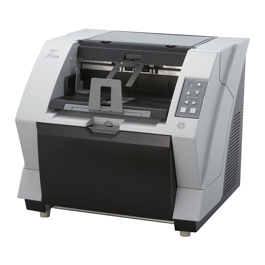
INTRODUCTION Thank you for purchasing the fi-5950 Image Scanner. The fi-5950 is an image scanner designed to scan various documents in large quantities. The fi-5950 has the following features. Improvement of color scanning speed (105 sheets or 210 pages per minute) with high resolution (300dpi) By the newly-developed high speed CCD and high speed image processing circuit, scanning speed (A4 color, 300dpi) of 105 sheets/210 pages per minute) is improved. -
Page 4: About This Manual
Pre- and Post imprinter option can be installed In today's document business, imprinters provide a vital tool for archiving, controlling and verification processes. For this scanner, you can select two optional types of imprinters, depending on your needs. The Pre-Imprinter Option prints information on the front side of the documents prior to the scanning. -
Page 5: Regulatory Information
10. SCANNER SPECIFICATIONS This chapter lists the scanner specifications. The “Getting Started” is supplied to this Scanner. This guide contains necessary information for getting started the scanner, also read the Getting Started. 1. PREPARING THE SCANNER This chapter describes how to prepare the scanner for use. 2. -
Page 6: Canadian Doc Regulations
FCC warning: Changes or modifications not expressly approved by the party responsible for compliance could void the user’s authority to operate the equipment. •The use of a shielded interface cable is required to comply with the Class ATTENTION B limits of Part 15 of FCC rules. The length of the SCSI interface cable must be 1.5 meters (5 feet) or less. - Page 7 Use in High-safety Applications This product has been designed and manufactured on the assumption that it will be used in office, personal, domestic, regular industrial, and general-purpose applications. It has not been designed and manufactured for use in applications (simply called “high-safety applications” from here on) that directly involve serious danger to life and health when an extremely high degree of safety is required, for example, in the control of nuclear reactions at nuclear power facilities, automatic flight control of aircraft, air traffic control, operation control in mass-transport systems, medical...
- Page 8 How Trademarks Are Indicated In This Manual References to operating systems (OS) are indicated as follows: Product Indication Windows 2000 Windows (*1) ® Windows 2000 Professional (Service Pack 4 or later) ® Windows XP Professional (Service Pack 2 or later), Windows XP ®...
-
Page 9: Preface
■ Note of Liability READ ALL OF THIS MANUAL CAREFULLY BEFORE USING THIS PRODUCT. IF THIS PRODUCT IS NOT USED CORRECTLY, UNEXPECTED INJURY MAY BE CAUSED TO USERS OR BYSTANDERS. Also, store this manual in a convenient and safe place so that it can be easily referred to during use of this product. -
Page 10: Symbols Used In This Manual
Symbols Used In This Manual This manual uses the following symbols in explanations in addition to warning indications. This symbol alerts operators to particularly important information. Be sure ATTENTION to read this information. This symbol alerts operators to helpful advice regarding operation. HINT A TRIANGLE symbol indicates that special care and attention is required. -
Page 11: Safety Precautions
The Operator Panel Language Display Apart from English, the operator panel can also display French, German, Italian, Spanish, and Chinese (Simplified). In this manual, the language display of the operator panel is shown in English. About Maintenance The user must not perform repairs on this scanner. Contact the store where you purchased the scanner or an authorized FUJITSU Image Scanner service provider to make repairs to this product. - Page 12 Do not take apart or modify the scanner as high-voltage components inside the scanner are dangerous. PFU assumes no liability to any damage caused by taking apart the scanner, as doing so is not covered under the warranty. The area around the part to which this warning label is affixed can become very hot. To avoid burns, never touch around the area indicated by this label.
- Page 13 Do not install the scanner in the following locations which are subject to high temperature, humidity, less ventilation, or dust. If placed in an area subject to high temperature, the cover may become overheated and deformed, causing the scanner to become hot, resulting in a fire.
- Page 14 Do not use a damaged power cable. Also, do not insert any cables or power plugs into loose sockets. Doing so may cause a fire or electric shock. Be careful of the following when handling the power cable: •Do not modify the power cable. •Do not place heavy objects on the power cable.
- Page 15 Do not use any aerosol sprays or alcohol based sprays to clean the scanner. Dust blown up by strong air from the spray may enter the inside of the scanner. This may cause the scanner to fail or malfunction. Sparks, caused by static electricity, generated when blowing off dust and dirt from the outside of the scanner may cause a fire.
- Page 16 If there is an electrical storm, disconnect the power cable from the AC outlet. Lightening can travel through wires and water pipes and damage the scanner, which may damage your property. Do not supply the power from the AC outlet where the devices requiring much power such as copying machines or paper shredders are connected.
-
Page 17: Table Of Contents
CONTENTS INTRODUCTION .......... i Regulatory Information ............iii Note of Liability ..............vii Preface ................vii Safety Precautions............... ix 1 NAMES AND FUNCTIONS OF PARTS..1 1.1 Names and Functions of Parts ........2 1.2 Operator panel ...............5 2 BASIC SCANNER OPERATIONS ....7 2.1 Turning the Scanner ON /OFF ........8 2.2 Opening and Closing the Hopper ........10 2.3 Opening and Closing ADF ...........12... - Page 18 3.9 Setting Auto Correction for Document Page Orientations ..............86 3.10 Multi Image Output ............89 3.11 Color/monochrome Auto Detection ......92 3.12 Not detecting Multifeed for fixed format .....95 4 DAILY CARE..........103 4.1 Cleaning Materials and Areas Requiring Cleaning ..104 4.2 Cleaning the Pad ............106 4.3 Cleaning the Rollers (using the cleaning sheet) ..107 4.4 Cleaning the Rollers (with a lint-free cloth) ....110 4.5 Cleaning the Transport path and the sensors ....114...
- Page 19 7.8 Scanning Mixed Documents ........168 8 SCANNER SETTINGS ......171 8.1 Scanner Settings ............173 8.2 Power saving setting ..........187 8.3 Offset/Scan scale ............188 8.4 Multifeed Detection ............190 8.5 Multifeed detection when scanning in manual feed mode ................195 8.6 Page Edge Filler (ADF) ..........196 8.7 Dropout Color ............198 8.8 Pre-Pick ..............199 8.9 Page Edge Filler (Automatic Page Size Detection) ...200...
- Page 20 9.4 Other Options ............227 SCANNER SPECIFICATIONS....229 10.1 Basic Product Specifications ........230 10.2 Installation Specifications ........232 10.3 Dimensions ..............233 INDEX ................IN-1 xviii...
-
Page 21: Names And Functions Of Parts
NAMES AND FUNCTIONS OF PARTS This chapter describes names and functions of various parts of the scanner. 1.1 Names and Functions of Parts..........2 1.2 Operator panel ................5... -
Page 22: Names And Functions Of Parts
1.1 Names and Functions of Parts This section describes the names of parts. ■ Front side Name Function Stopper Prevents ejected documents from dropping off the scanner. Stacker side guide For aligning ejected documents to a certain width. Top cover Cover to access the consumables storage box and Post-Imprinter option (sold separately). -
Page 23: Rear Side
■ Rear side Name Function Main power switch For switching the power supply ON/OFF. Power connector For connecting the AC cable. SCSI ID Switch Sets the scanner’s SCSI ID. SCSI connector For connecting the SCSI cable. USB connector For connecting the USB cable. Extended memory For connecting an extension memory (sold separately). -
Page 24: Removable Parts
■ Removable Parts Name Description Document smoother Attached when the stacker position is set to align the ejected document by the leading edge (see page 24), or when scanning documents with different widths (see page 67). Pick Rollers Rollers that pick the paper from the hopper into the ADF. This is a con- sumable item. -
Page 25: Operator Panel
1.2 Operator panel The operator panel is located on the right side of the scanner. The panel consists of a Function Number Display, buttons and LEDs. Function number display Function Hopper Height Paper Thickness Thin Thick Send to Scan Name Function Function Number dis- Shows the status of the scanner. -
Page 26: Indications On The Function Number Display
Operator Panel Overlays sheets in French, German, Italian, Spanish and Chinese (Simplified) are provided with the scanner. To change the overlay, HINT open the plastic cover of the Operator Panel. ■ Indications on the Function Number Display The following shows the indications on the Function Number Display. Descriptions Lights only one time upon turning on the scanner. -
Page 27: Basic Scanner Operations
BASIC SCANNER OPERATIONS This chapter describes basic scanner operations. This chapter explains operations using the screens of Windows XP. Depending on your OS, your PC's screen shots and the operation may be different from this manual. Be aware that when the TWAIN driver, or the ISIS driver is updated, the screens and operations noted in this chapter may be changed slightly. -
Page 28: Turning The Scanner On /Off
2.1 Turning the Scanner ON /OFF ■ Turning the Power ON When SCSI interface is used, turn on the scanner power first. Turn on the ATTENTION PC when the scanner displays “1” on the Function number display. Press “I” side of the main power switch located on the back of the scanner. -
Page 29: Turning The Power Off
■ Turning the Power OFF Hold the Power button for at least two seconds. ⇒ The Power button light goes off and the scanner becomes disconnected. If the scanner will not be used for an extended period, turn off the scanner’s main power switch on the back and unplug the power cable. -
Page 30: Opening And Closing The Hopper
2.2 Opening and Closing the Hopper ■ Opening the Hopper Hold the centrer of the upper part of the Hopper. Flip down the Hopper gently. 2.2 Opening and Closing the Hopper... - Page 31 ■ Closing the Hopper Remove the document if there is any on the Hopper. Slide the extension in the Hopper. Hopper extension Restore the original position of the hopper if the height of Hopper is adjusted. Lower the hopper to the bottom by pressing the button.
-
Page 32: Opening And Closing Adf
2.3 Opening and Closing ADF ■ Opening ADF Remove the document if there is any on the stacker. Press the ADF cover open button. The cover is slowly opened. ⇒ 2.3 Opening and Closing ADF... - Page 33 ■ Closing ADF Hold the ADF cover with both hands and press it down slowly. Press the ADF cover until it is fixed. • When closing the ADF, make sure that nothing is left inside the ADF. ATTENTION • Be careful not to have your fingers caught. 2.3 Opening and Closing ADF...
-
Page 34: Opening And Closing Top Cover
2.4 Opening and Closing Top Cover Under the Top cover, there are a storage tray for storing the consumables and cleaning goods and a space for installing the Post-Imprinter. When you use the tray or access the Post-Imprinter, open the top cover as follows. -
Page 35: Setting The Hopper Height
2.5 Setting the Hopper Height When there is no alarm (the function number display is showing “1”), the Hopper height can be adjusted. When the scanning load is not very heavy, setting the hopper higher will shorten the time it moves to the feeding position. - Page 36 The adjustment is done by using the Operator Panel on the scanner. Function Hopper Height Paper Thickness Thin Thick Send to Scan When you press the button, the hopper is raised one step higher.(Low Middle High) When pressing the button, the hopper is lowered one step lower.(High Middle Low) Immediately after the scanner is turned on, the Hopper is initially set to Low.
-
Page 37: Loading Documents On The Hopper
2.6 Loading Documents on the Hopper ■ Preparing the Document Align both edges of the documents. For how to scan the document with different widths, refer to “3.3 Scanning Documents with different widths” on page HINT Fan the documents. 1) Take a stack of documents about 15mm to 20mm thick (1/2 to 3/4 inch). 2) Hold both ends and bend the documents into an arch. - Page 38 ■ Setting the Document There are 2 ways to set documents on the hopper. (1) Set the document at the center of the hopper (mainly for document of equal size pages). (2) Set the document by either side of the hopper (mainly for document of different size pages, or you want to align the document by the side instead of the center line).
- Page 39 • Make sure that the document stack does not exceed the maximum ATTENTION height mark on the inner side of the Side guides. • For long documents, use the hopper extension. height mark Hopper extension Start the scanner application and scan the document. For the details on how to scan using ScandAll PRO, refer to “2.10 Scanning Documents”...
- Page 40 Lock the side guide not to be used. Flip up the lock switch on the front side of the side guide to lock it. Locked! Lock Switch Move the other side guide to the desired position while pressing down the lock lever. サイドガイド...
- Page 41 Make sure that all the pages fall under the pick roller. (Otherwise they will ATTENTION not be picked) Pick roller Start the scanner application and scan the document. For the details on how to scan using ScandAll PRO, refer to “2.10 Scanning Documents”...
-
Page 42: Setting Up The Stacker
2.7 Setting up the Stacker The document set on the hopper, once scanned, will be ejected onto the stacker. You can adjust the inclination of Stacker table to align the leading edge of document or not. Also you can fix the height of Stacker table for thin paper stacking. Set up the Stacker by adjusting the Stacker extension, Stopper, Side Guides and Stacker's inclination. - Page 43 When scanning long pages (longer than A3), the document may be longer than the stacker extension even if it’s pulled to the outermost position. In case HINT like this, place a thick paper about the size of A4 on the stopper and make a slope as depicted below.
- Page 44 ■ Changing Stacker inclination/motion The location of the stacker can be switched when ejecting documents by fixing the stacker height in the appropriate position, or by using either the horizontal setting for bottom edge alignment or the tilting for- ward setting for leading edge alignment. The factory default is set to the horizontal setting. When using the tilting forward setting for leading edge alignment, follow the procedure below to switch the position of the stacker.
- Page 45 Move your hands away from the stacker slowly. ⇒ The stacker will be fixed in a position tilting forward. • When set to “Bottom edge” position, the stacker does not move up or down and becomes immovable even during scanning operation. HINT •...
- Page 46 Move your hands away from the stacker slowly. ⇒ The stacker will be fixed in a horizontal position. • When set to the “bottom edge alignment” position, the stacker will automat- ically adjust its height according to its load. HINT •...
-
Page 47: Using The Document Smoother
2.8 Using the Document smoother The ejected document may not stack correctly when the stacker’s angle is adjusted to the tilting forward setting (see page 24), or when scanning document of different size pages (see page 67). If that is the case, install the Document Smoother as described below. - Page 48 While bending the center part, insert the other tab into the scanner slit. ⇒ It will look like this when installed. Document Smoother 2.8 Using the Document smoother...
-
Page 49: Setting The Paper Thickness
2.9 Setting the Paper Thickness When multifeeds or paper jam occurs frequently, adjust the paper thickness by using the Paper Thickness button on the operator's panel. (Under normal circumstances, use the default setting.) Set the paper thickness on the Operator Panel. Function Hopper Height Paper Thicknes s... -
Page 50: Scanning Documents
2.10 Scanning Documents This section explains about the basic flow of scanning operations. In order to use the scanner to scan documents, you need a scanner driver and an application that supports the driver. The scanner is bundled with the TWAIN-compliant driver called "TWAIN Driver", the ISIS-compliant driver called "ISIS Driver", the image processing software "Kofax VRS", and the "ScandAllPRO (TWAIN driver/ISIS driver)"... - Page 51 Start up the application to use for scanning. ScandAll PRO will be used here as an example to explain the procedure. When ScandAll PRO is launched For information on how to launch ScandAll PRO, refer to "How to Use ScandAll PRO". Select a scanner driver to use for scanning.
- Page 52 Select a scanner. For TWAIN Driver For ISIS Driver 2.10 Scanning Documents...
- Page 53 Launch a scanner driver from the application. For TWAIN Driver For ISIS Driver 2.10 Scanning Documents...
- Page 54 In the scanner driver’s setup dialog box, configure the scan settings. Perform a scan. For information on how to scan using ScandAll PRO, refer to "How to Use ScandAll PRO". Save the scanned images in a file. Procedures and operations slightly vary depending on the application used. For details about how to scan using ScandAll PRO, refer to "How to Use HINT ScandAll PRO".
-
Page 55: Starting Scanning With Button
2.11 Starting Scanning with Button Pressing the [Scan] / [Send to] button can start an application previously linked. However, you need to set the application for [Scan] and [Send to] button referring to “2.14 Before Using [Scan] / [Send to] button” on page Load the documents on the hopper. -
Page 56: Feeding Documents Manually
2.12 Feeding Documents Manually Besides the “Automatic Feed Mode” which automatically scans the document set on the hopper, the scan- ner can also scan documents in the “Manual Feed Mode”. In addition, the “Manual Feed Mode” is divided into 2 types: <1>... - Page 57 ■ Single Feed Lift up the Pick roller unit. Lift up the small plate on the left side using your finger. Pick Roller Unit Hopper The Pick roller unit will click into place. ⇒ The hopper will move up to the manual feed position. ⇒...
-
Page 58: Start Scanning
Start the application and display the scanner driver screen. Set the scanning condition. For the information about how to run the scanner driver, refer to “2.10 Scanning Documents” on page Start scanning. When using the TWAIN driver, click the [Scan] button on the following screen. Insert the document until the top edge touches the rollers on the inside. - Page 59 Repeat the procedure 5 until all the documents are scanned. After a certain time period of inactivity or at pressing of [Send to] button, the scanner will recognize it as “no document” and stop scanning. For setting the timeout for feeding the document manually, refer to section “8.25 Timeout for Manual Feeding”...
- Page 60 ■ Continuous Feed Open the hopper if it is closed. Refer to section “2.2 Opening and Closing the Hopper” on page Press down the Hopper Height Button ( ) on the Operator Panel for more than 3 seconds. Function Hopper Height Paper Thicknes s Thin Thick...
- Page 61 Start scanning. When using the TWAIN driver, click the [Scan] button on the following screen. Load the documents towards the back of the hopper. When more than one sheet is loaded, only the one on the top of the stack will be fed. ⇒...
- Page 62 Repeat the procedure 6 until all the documents are scanned. ⇒ After a certain time period of inactivity or at pressing of [send to] button, the scanner will recognize it as “no document” and stop scanning. For setting the timeout for feeding the document manually, refer to section “8.25 Timeout for Manual Feeding”...
-
Page 63: Configuring The Scan Settings
2.13 Configuring the Scan Settings ■ TWAIN Driver The TWAIN driver is a software driver that conforms to the TWAIN standard. This driver can be used with an application that supports TWAIN to perform scanning. Normally, the scanner driver is launched via an application, and then the scan settings are configured in the setup dialog box of the driver (some applications may not display the setup dialog box). -
Page 64: Scan Type
Scan Type Specifies the feeding method, the side(s) to be scanned (Front Side, Back Side, Duplex) or details of Long page (Front Side, Duplex) details of Long page (Front Side, Duplex) *. * Refers to documents larger than Double Letter (11 × 17 in.)/A3. Paper Size Select the size of documents to be scanned from this list. - Page 65 [Option...] button You can set up the details of optional functions on the window below. [Rotation] tab Select this tab when setting items such as flip side rotation, image rotation, hole punch removal, skew correction, size and length detection, black background, and overscan. [Job/Cache] tab Select this tab when setting cache mode, job controls, multifeed detection, blank page skipping, etc.
-
Page 66: Isis Driver
[Config...] button Click this button for configuring the Setting Files. You can save the changed settings as a Setting File. From next scanning, the settings are quickly changed by using these Setting Files. For details of each function, refer to the “TWAIN Driver Help”. - Page 67 [Main] tab Camera Selects the document’s side (front or back) to be scanned. The check-marked side(s) will be scanned. By marking only the checkbox(es) of Front Image, you can scan the one side of the documents (simplex scan), and by marking the checkboxes of both Front and Back Images, you can scan the both sides of the documents (duplex scan).
-
Page 68: Dots Per Inch
Mode Select a color mode suitable for the purpose from the menu. Image Processing Scans data in binary (black and white) using Image Processing Soft- ware Option. When this mode is selected, the [Setup IPC...] button below becomes available. (Note that only when Image Processing Software Option is installed in the computer, it is displayed.) Black and White Scans data in binary (black and white). - Page 69 Dither Select the halftone pattern for halftone scanning. This setting is available when “Black and White” is selected in the “Mode”. Pattern 1 This setting is suitable for scanning dark photographs. Pattern 2 This setting is suitable for scanning dark-colored documents containing both text and photographs.
- Page 70 [Layout] tab Page Orientation Specifies the page orientation (Portrait or Landscape). Paper Size Selects a paper size according to the size of the document to be scanned. Select any size from the list. [Scan Area...] button Opens the [Scan Area] dialog box. You can specify the area to be scanned.
- Page 71 [Image Processing] tab Quick Set You can select a preset pattern for image enhancement. By selecting the one from the list, you can quickly set the details of the image enhancement processing. Available patterns are as follows: Normal documents This item is suitable for scanning the documents like the ones used (default) in offices.
-
Page 72: Image Emphasis
Overscan Scans the document allowing more margins than the ones of paper size specified at [Paper Size:]. Thus, the result of scanning is bigger than the specified paper size. Image Emphasis This option processes the outline of the scanned image as follows: Low, Mid, High Emphasizes the contour of images. - Page 73 [Paper Handling] tab Pre-pick With this option, you can enable or disable Pre-picking. Pre-picking is an operation that feeds documents into the ADF (to the scanning position) before starting actual scanning operation. Select “On” to shorten the required time for scanning. Backing With this option you can set the background color (Black/White).
- Page 74 [Gamma] tab Pattern Specifies how to correct Gamma. Available correction patterns are: “Normal”, “Soft”, “Sharp”. “Custom” is selectable when “Color” is selected on the Main tab. Camera Specifies side(s) to which you want to apply the settings made on this window. Custom Properties Can be specified when “Cutom”...
- Page 75 [Color Dropout] tab Red, Green, Blue (Light’s three primary colors) or any color can be selected to drop out from the docu- ments to be scanned. For example, if you specify “Red” when scanning black letters with red outlines, only the black part of the letters are scanned.
- Page 76 [Edit...] button Clicking this button displays the “Select Dropout Color” window and you can specify any color to drop out as checking Dropout Image. Original Image The sample color is shown. By clicking colors in Original Image, you can select the color to drop out from the image.
- Page 77 [Compression] tab You can configure compression settings for scanning images in color or gray scale on this tab. JPEG Quality: Specify the compression level and image quality. Sample Ratio: Specify the sample ratio by which images are compressed. The file size of images compressed by the ratio of YUV4:2:2 is smaller than that of images compressed by the ratio of YUV4:4:4.
- Page 78 [Imprinter] tab You can make settings for Pre-/Post-Imprinter Options (to be purchased separately). Unless Imprinter Option is installed, this tab will be unshown. Do not print Imprinter is not used. Print before scanning With Pre-Imprinter, printing is done on the front face of the document.
- Page 79 Date Specifies how to display the date. Format: You can specify how to display the date. Delimiter: You can select delimiters (grouping separators). Counter Specifies the rule of display. Initial Value: You can specify the initial vale. Field Width: You can specify the number of digits for the counter. (3 to 8 digits).
-
Page 80: Before Using [Scan] / [Send To] Button
2.14 Before Using [Scan] / [Send to] button By setting the link of the application software to the [Scan] button and [Send to] button, you can launch the linked application by simply pushing the button. Select [Control panel] from the [Start] menu. Select [Property] from [Scanner and Cameras]. - Page 81 Select the application executed by the event. For Windows XP, Windows Server 2003 and Windows Vista, select [Performing selected program] under [Performing] and then select the application to be processed. Click OK. 2.14 Before Using [Scan] / [Send to] button...
-
Page 82: Resuming From Power Saving Mode
2.15 Resuming from Power Saving Mode Power saving mode saves the power consumption of the scanner while the power is turned on. When the scanner is left without operation for 15 minutes or more (factory initial setting), it automatically enters the power saving mode. -
Page 83: Scanning Various Types Of Documents
SCANNING VARIOUS TYPES OF DOCUMENTS This chapter describes how to scan various types of documents. This chapter explains operations using the screens of Windows XP. Depending on your OS, your PC's screen shots and the operation may be different from this manual. Be aware that when the TWAIN driver or the ISIS driver is updated, the screens and operations noted in this chapter may change. -
Page 84: Double Sided Scanning
3.1 Double Sided Scanning When you want both sides of a document to be scanned at the same time, set the feeding option to “Duplex”. Below is the procedure with TWAIN driver. Set the document on the hopper. Refer to section “2.6 Loading Documents on the Hopper”... -
Page 85: Scanning Documents Longer Than A3
3.2 Scanning Documents Longer than When scanning documents longer than A3, set the feeding option to “Long Page”. This scanner can scan documents up to 3,048mm (120inch) long. Below is the procedure with TWAIN driver. Set the document on the hopper. Refer to section “2.6 Loading Documents on the Hopper”... - Page 86 Set [Scan Type:] to “Long Page (Front Side)” or “Long Page (Duplex)”. Choose “Long Page (Front Side)” when scanning one side; “Long Page (Duplex)”, both sides. ⇒ The “Set the document size” screen will appear. Click [OK] after setting the document When excessively long length is specified, the scanning speed may be slow.
-
Page 87: Scanning Documents With Different Widths
3.3 Scanning Documents with different widths When you scan a batch of documents with different widths, follow the instruction below. Align the leading edge of the documents. Aligning the document Aligning the document alongside their center line with its left (or right) edge This section describes the procedure to align the document alongside their center line. - Page 88 Load the documents so that each sheet can be reached by the pick roller. ATTENTION (If the documents are not placed below the Pick roller, the document feed- ing will not be possible.) Pick roller Align the side guides to the width of the widest document. 原稿...
-
Page 89: Configuration Window
Start up the scanner driver. Refer to “2.10 Scanning Documents” on page 30 for further information about how to start up the scanner driver. Perform the settings for the scanning on the scanner driver’s configuration window. For the TWAIN driver Paper size: (Main display) Set the width of the widest, and the length of the longest document. -
Page 90: Saving Scanned Images In Pdf Format
3.4 Saving Scanned Images in PDF Format To save scanned images in PDF format, Adobe Acrobat must be installed on your PC. Adobe Acrobat can be installed from the provided Adobe Acrobat DVD-ROM. There are two ways to create PDF files: (1) By ScandAll PRO(page 71) Recommended when you want to create PDF files according to your business needs, by... - Page 91 - When you scan in a resolution lower than Adobe’s recommended resolution with [Color/Grayscale] and/or [Monochrome] under [Compression] set to [Adaptive] in Acrobat, the output image may not be satisfactory. Solution: Under [Compression], set [Color/Grayscale] and/or [Monochrome] to a setting other than [Adaptive].
- Page 92 From the [File] menu, select [Create PDF] - [From Scanner] - [Custom Scan]. ⇒ [Custom Scan] dialog box appears. Select “FUJITSU Fi-5950d” at [Scanner] . If your document is scanned by the default settings, the output image may ATTENTION not be satisfactory. It is recommended to change the settings as follows: 1.
- Page 93 Click the [Options] button. ⇒ The [Scanner Options] dialog box appears. Select [Show Scanner’s Native Interface] for [User Interface], and then click the [OK] button. ⇒ The [Scanner Options] dialog box closes and it returns to The [Custom Scan] dialog box. Click the [Scan] button.
- Page 94 Configure settings such as [Resolution] and [Paper Size], and then click the [Scan] button. The scanned image is displayed. ⇒ Select [Save as...] from [File] menu to save the scanned image. For the details on Adobe Acrobat operations, refer to the Adobe Acrobat Help.
- Page 95 ● How to reduce the file size by Acrobat Distiller Depending on the scan setting, the file size may be greatly increased. To reduce the data size, try saving the scanned image by the following method (note that this takes longer than usual to save): From the [File] menu, select [Print].
-
Page 96: Excluding A Color From The Image (Drop Out Color)
3.5 Excluding a Color from the image (drop out color) One of the primary colors: red, green ,blue or any other color can be removed (dropped out) from the scanned image data. For example, if the document contains black text in a green frame, you can set the scanner to read only the text and eliminate (drop out) the green frame.(Dropout color will only work when scanning in monochrome or grayscale mode). - Page 97 Select the color to be dropped out from [Dropout Color] under [More]. For example, if the document contains black text in green frame, select [Green] so that the scanner only reads the text and eliminates the frames. If you do not wish to have any colors dropped out, select “None”. If you wish to drop out a customed color, please select [custom pattern 1-3].
-
Page 98: Excluding A Color From The Image (Drop Out Color)
Dropout Image The image as it will be generated after the dropout is displayed. Dropout color The selected dropout color will be shown as numeric value and as color sample. You can enter a numeric value directly or use the [ ▲ ]/[ ▼ ] buttons to change the dropout color. Priority Black If you do not wish to drop out text from the image, please mark “Priority Black”. -
Page 99: Skipping Blank
3.6 Skipping blank Pages If enabled, the scanner will automatically detect blank pages of the documents and remove them from the scanned image. For example, when double sided and single sided pages are scanned together, the blank side of the single sided pages will be skipped during scanning. Change settings in the [TWAIN Driver] dia- log box to enable skipping blank pages at scanning documents. - Page 100 Check the [Blank Page Skip] box. When the check box is marked, “Cache Mode” will change to “Use both memory”. Using the slider control under [Blank Page Skip], specify the Blank Page Skip degree. <In Binary/Halftone mode> For white pages, use the [Black Dots Ratio] slider bar to set the skip condition. For black pages, use the [White Dots Ratio] scroll bar to set the skip condition.
- Page 101 Click [OK] when done. The [TWAIN Driver] dialog box will return. continue from there. 3.6 Skipping blank Pages...
-
Page 102: Detecting Multifeeds
3.7 Detecting Multifeeds “Multifeed” is an error that occurs when two or more sheets are accidentally fed into the ADF at the same time. You can set the scanner to display an error message or ring the buzzer when the scanner detects a multifeed. - Page 103 Select the detection conditions from [Multifeed Detection] under [ADF Option]. You can choose the following: None Multifeed detection is not performed. Check overlapping The scanner monitors for the overlapping of documents. The scanner detects a multifeed by differences in ultrasonic propagation. When this method is slected, two more options are available specified by other sections.
-
Page 104: Correcting Skewed Documents
3.8 Correcting skewed Documents You can set the scanner to automatically detect and correct skewed documents that are fed into the ADF. The configuration is done through the scanner driver. The following shows the procedure for changing the setting from the [TWAIN Driver] dialog box. Start TWAIN Driver from your scanning application. - Page 105 Select the [Automatic Page Size Detection] from the [Automatic Size and Skew Detection] menu. Click the [OK] button. The display returns to the scanning operation [TWAIN Driver] dialog box. When using either of the following documents, the Automatic page size ATTENTION detection may not function correctly.
-
Page 106: Setting Auto Correction For Document
3.9 Setting Auto Correction for Document Page Orientations You can direct the scanner to automatically correct a batch of documents with a mixture of page orienta- tions. Opqrstu Vwxyz. Vwxyz. Abcdefg Opqrstu Hijklmn Hijklmn Abcdefg Output images Originals The following shows the procedure for changing the setting from the [TWAIN Driver] dialog box. Start TWAIN Driver from your scanning application. - Page 107 Select the [Rotation] tab, and then select [Automatic] under [Rotation Degree]. •This function determines a document page orientation based on the char- ATTENTION acters printed on it. So it may not work properly for the following kinds of documents: − Documents with a resolution for scanning not between: 300 dpi and 600 dpi (in Black &...
- Page 108 •To judge text in documents, use a language that is set in Windows’s Regional and Language Options. •The image orientation may not be corrected properly depending on the scanner driver setting at scanning (e.g. dithering). •If you cannot correct the image orientation properly, use the Edge Empha- sis function of the drivers to correct it.
-
Page 109: Multi Image Output
3.10 Multi Image Output It is possible to get an output both in Color/Grey scale and binary black and white. This function may not work properly depending on the application software you use. Original Output Example : Color document scanned with Multi Image. The Multi Image setting can be done on the Scanner Driver. - Page 110 ⇒ The [Multi image output] dialog box will be displayed. Select [Multi image output] under “Output mode”. Set the order of the output in “Order (for Multi image output)”. Primary: Color/Grayscale Secondary: Binary The output order will be: [Color or Grey scale images] [Binary monochrome images] Primary: Binary Secundary: Color/Grayscale...
- Page 111 Select under “Select Current face” the side of your choice and perform then for each scan settings on the main configuration screen. Click the [Scan] button to scan the document. 3.10 Multi Image Output...
-
Page 112: Color/Monochrome Auto Detection
3.11 Color/monochrome Auto Detection The scanner detects whether the scanned document is color or binary monochrome. According to this detection, the images will be output in color (or grey scale) for colored documents, ide binary black and white for monochrome documents. - Page 113 ⇒ The [Multi Image output] dialog box will be displayed. Under [Output Mode Selection], check [Color/Monochrome Auto Detection]. Select under [Current Side Selection] the side of your choice and perform then for each scan settings on the main configuration screen. The scan settings are done in advance, for the case documents are detected as [Color/Grey scale] or [Monochroe (binary black and white)].
- Page 114 Click the [Scan] button to scan the document. 3.11 Color/monochrome Auto Detection...
-
Page 115: Not Detecting Multifeed For Fixed Format
3.12 Not detecting Multifeed for fixed format When sheets with glued photographs or sticky notes are scanned, the scanner can accidentally detect a multifeed error, and scanning is interrupted. This section explains "Intelligent Multifeed Function", or a resolution function that eliminates such a problem (hereinafter referred to as "this function"). This function has one manual mode and two automatic modes as follows: Manual mode in which multifeed error detection is disabled by manipulating the Operator •... -
Page 116: Intelligent Multifeed Function
■ Intelligent Multifeed Function There are three modes; select one according to your needs. Select a mode by using the Software Operation Panel. For how to select a mode, see section 2. Item in Method to bypass Multifeed Applicable case Comments Software Operation... - Page 117 ■ How to Configure Settings with Software Operation Panel First, make sure that the scanner is connected to the personal computer, and then turn on the scanner. Second, press the [Function] button until "C" is displayed on the Operator Panel. Third, press the [Send to] button. Finally, the Software Operation Panel window will appear.
- Page 118 • Remember multifeed pattern at power-off Specify whether or not to remember the multifeed pattern upon turning off the power. When [Remember] is specified, the multifeed pattern used before the power-off remains available after turning the power back on (Up to 8 patterns can be stored in memory). 3.12 Not detecting Multifeed for fixed format...
- Page 119 ■ Before Using This Function Configure the following settings before using this function: When the TWAIN driver is used, select [Use Memory on Scanner] or [Use both Memory] as [Cache Mode] on the [Job/Cache] tab of the "Option" dialog box. Otherwise you can not continue scanning after a multifeed error.
- Page 120 [ISIS driver] Mark the "On" checkbox under "Multifeed Recovery" and set "Auto-cancel Timer" to 0 or any value (minutes) on the [Paper Handling] tab of "Properties for Fujitsu fi-5950..." dialog box. Auto-cancel Timer: Scanning is not restarted for the set period of time (minutes) after a multifeed error.
- Page 121 ■ Descriptions After a multifeed error, press the [Send to] button to eject sheets from the transport path, or open the cover and remove sheets from the transport path. Return the ejected or removed sheets onto the hopper. When the sheets are removed, the function number displayed changes as follows: Multifeed error No sheets in the transport path...
- Page 122 Note 1: In this mode, up to 32 overlap patterns can be remembered (stored in memory). When the 33rd overlap pattern is detected, the first-remembered pattern is deleted from memory. Note 2: The remembered overlap patterns can be deleted from memory by pressing the [Function] but- ton for 2 seconds or longer while the function number is blinking.
-
Page 123: Daily Care
DAILY CARE This chapter describes how to clean the scanner. • Take care not to pinch your fingers inside the ADF. WARNING • The glass inside the ADF becomes hot during operation. Be careful not to get burned. 4.1 Cleaning Materials and Areas Requiring Cleaning ..104 4.2 Cleaning the Pad ..............106 4.3 Cleaning the Rollers (using the cleaning sheet) .....107 4.4 Cleaning the Rollers (with a lint-free cloth) ..... -
Page 124: Cleaning Materials And Areas Requiring Cleaning
4.1 Cleaning Materials and Areas Requiring Cleaning ■ Cleaning materials Cleaning materials Part No. Remarks Cleaning sheet CA99501-0016 (*1) 20 sheets/pack Cleaner F1 PA03950-0352 (*1)(*2) 1 bottle, 100ml/bottle Moisten cloth with this fluid and wipe the scanner to clean. Cotton swab Commercially available Cleaning Wipe... - Page 125 ■ Locations requiring Cleaning and Cleaning Frequency The following shows the standard cleaning frequency for each area requiring cleaning. cleaning method cleaning sheet cloth moistened with cleaner F1 cleaning cycle every 10,000 scanned every 10,000 scanned pages (*1) pages (*1) Pick rollers Brake roller Separator rollers...
-
Page 126: Cleaning The Pad
4.2 Cleaning the Pad Open the ADF cover. For details, refer to “2.3 Opening and Closing ADF” on page ADF cover Wipe the Pad (the parts of rubber) with a lint-free cloth, moistened with cleaner F1, in the direction indicated by the arrows. It may take long before the cleaner vaporizes if a large quantity is used. -
Page 127: Cleaning The Rollers (Using The Cleaning Sheet)
4.3 Cleaning the Rollers (using the cleaning sheet) Use the cleaning sheet to clean the upper and lower ADF transport path and the rollers. Open the Pre-Imprinter Cover when the power is off. Pre-Imprinter Cover Scan While pressing the [Scan] button , press the power button switch on the scanner. - Page 128 Set the side guide of the hopper to B4 width. For details, refer to “2.6 Loading Documents on the Hopper” on page Pull out the stacker extension and adjust it to the length of the cleaning sheet. For details, refer to “2.7 Setting up the Stacker”...
- Page 129 10. Place the same cleaning sheet with the adhesive side facing up on the hopper table, aligning the right side with the side guide, as shown in the illustration below. Scan 11. Press the [Scan] button 2 times (3 times, if Imprinter option is installed.) ⇒...
-
Page 130: Cleaning The Rollers (With A Lint-Free Cloth)
4.4 Cleaning the Rollers (with a lint-free cloth) Move the Hopper down to the "low" position if it is set in an upper level. For details, refer to “2.5 Setting the Hopper Height” on page Open the ADF cover. For details, refer to “2.3 Opening and Closing ADF”... - Page 131 Clean the Pick roller and the rubber surface of the Separator rollers using the cleaner F1. Pick roller Separator roller Roller cover It may take long before the cleaner vaporizes if a large quantity is used. ATTENTION When cleaning the scanner parts, dampen a cloth with modest quantities of the cleaner.
- Page 132 Remove the Brake roller. Move the roller slightly to the right, then pull it upwards to remove it, as shown below. Brake roller Clean the rubber surface of the Brake roller using a lint-free cloth, moistened with the cleaner F1. Brake roller Install the Brake roller again after cleaning.
- Page 133 11. Clean the Feed rollers (metal rollers, each set consists of 2 rollers, 9 locations) on the upper side of the lower transport path using a lint-free cloth moistened with the cleaner F1. Take care especially to remove black stains on the rollers, since such stains are deteriorating the feeding performance.
-
Page 134: Cleaning The Transport Path And The Sensors
4.5 Cleaning the Transport path and the sensors Open the ADF cover. For details, refer to “2.3 Opening and Closing ADF” on page Clean the whole transport path (stainless and glass parts) using a lint-free cloth moistened with the cleaner F1. If the transport path is stained with paper dust or other debris, please vac- uum-clean it carefully. - Page 135 It may take long before the cleaner vaporizes if a large quantity is used. ATTENTION When cleaning the scanner parts, dampen a cloth with modest quantities of the cleaner. In addition, wipe off the cleaner completely with a soft lint- free cloth to leave no residue on the surface of the cleaned parts.
- Page 136 Clean the IMP top-sensor (one piece), RED top-sensor (one piece), and REJ sensor (one piece) installed in the lower transport path using a cloth moistened with the cleaner F1. REJ sensor RED top-sensor IMP top-sensor Clean the IMP top-sensor (one piece), RED top-sensor (one piece), and REJ sensor (one piece) installed in the upper transport path using a cloth moistened with the cleaner F1.
- Page 137 Clean the EXT sensor (one piece) located near the outlet in the upper transport path using a cotton swab moistened with the cleaner F1. EXT sensor 4.5 Cleaning the Transport path and the sensors...
- Page 138 Clean the surface of two pads on the Hopper with a lint-free cloth, moistened with cleaner F1. Friction seat Close the ADF cover. For details, refer to “2.3 Opening and Closing ADF” on page If all the cleaning is done, reset the Cleaning counter by referring “5.2 How to check and reset the Consumable/Cleaning Counter”...
-
Page 139: Replacement Of Consumables
REPLACEMENT OF CONSUMABLES This chapter describes how to replace consumables. 5.1 Consumables and Replacement Cycle......120 5.2 How to check and reset the Consumable/Cleaning Counter ..............121 5.3 Replacing the Pad ..............125 5.4 Replacing the Pick Roller ..........126 5.5 Replacing the Separator Rollers ........128 5.6 Replacing the Brake Roller..........131... -
Page 140: Consumables And Replacement Cycle
5.1 Consumables and Replacement Cycle The following table lists the Part No. and the standard replacement cycle of the consumables. It is recom- mended that you stock extra consumables before the ones in the scanner reach the end of Their service life. The consumables must be replaced periodically. -
Page 141: How To Check And Reset The Consumable/Cleaning Counter
5.2 How to check and reset the Consumable/Cleaning Counter This section describes the procedure of the following items using Software Operation Panel in PC. Confirmation of consumable usage and cleaning cycle. • Counter reset after replacing the consumable or cleaning the scanner. •... - Page 142 Select the [Device Settings] tab. In this window, the following items can be confirmed. Total Page Count(ADF): The total number of scanned sheets. After cleaning: The number of sheets, scanned since last scanner cleaning. Pad: The number of sheets, scanned since last exchange of the Pad. Brake Roller: The number of sheets, scanned since last exchange of the Brake roller.
- Page 143 ■ Resetting of the consumable/cleaning counters Reset the consumable/cleaning counter(s) every time you replace the consumable or clean the scanner, fol- lowing the procedure given below. In View Only mode, the Software Operation Panel cannot be reset. For ATTENTION details on "View Only mode", refer to “Password Setting”...
- Page 144 ■ Consumable/Cleaning message The following message may appear while using the scanner: Consumable message: Cleaning message: Replace the consumable or clean the scanner when this message is sisplayed. After clicking the [Ignore] button, this message will disappear and scanning will continue. Replace the consumable as soon as possible.
-
Page 145: Replacing The Pad
5.3 Replacing the Pad Open the ADF cover. Refer to “2.3 Opening and Closing ADF” on page Move the Pad to the left, than pull it up in order to remove it from the scanner. Install the new Pad in the reversed order of the removable. Close the ADF cover. -
Page 146: Replacing The Pick Roller
5.4 Replacing the Pick Roller Open the ADF cover. Refer to “2.3 Opening and Closing ADF” on page Roller cover Open the roller cover. Put your fingers in the depression on the left and right side and pull the cover towards you to open it. - Page 147 While pulling up the tab away from the shaft, slide the Pick rollers (2 rollers, left and right) from the shaft for removal. Pick Roller Install the new Pick rollers (2 rollers, left and right) in the reversed order of the detachment. Put the roller correctly on the shaft, until it is locked in place.
-
Page 148: Replacing The Separator Rollers
5.5 Replacing the Separator Rollers Open the ADF cover. Refer to “2.3 Opening and Closing ADF” on page Roller cover Open the Roller cover. Put your fingers in the depressions on the left and right side and pull the cover towards you to open it. - Page 149 Slide Separator rollers (2 rollers, left and right) away from each other along the shafts for removal as shown below. Separator roller Shaft ⇒ The shaft will be locked in outer position and stays there. Remove the rollers from their shafts. Remove both, the left and the right rollers.
- Page 150 Close the roller cover. ⇒ The Separator rollers will move to their original position automatically. Roller cover Separator roller Close the ADF cover. Refer to “2.3 Opening and Closing ADF” on page Reset the counter of the Separation roller. Refer to “5.2 How to check and reset the Consumable/Cleaning Counter”...
-
Page 151: Replacing The Brake Roller
5.6 Replacing the Brake Roller Move the Hopper down to the "low" position if it is set in an upper level. For details, refer to “2.5 Setting the Hopper Height” on page Open the ADF cover. Refer to “2.3 Opening and Closing ADF” on page Pad cover Open the Pad cover on the lower transport path. - Page 152 Remove the Brake roller Lift up the left side of the Brake roller and remove the left shaft. Then pull the right shaft out of its hole to remove it. Brake roller Install the new Brake roller. After inserting the right end of the shaft into the hole, attach the left end. Brake roller Close the Pad cover.
-
Page 153: Solving Common Problems
SOLVING COMMON PROBLEMS This chapter describes how to clear document jams, how to remedy other problems, items to be checked before contacting an authorized service provider and how to check labels on the scanner. 6.1 Clearing Document Jams ..........134 6.2 Error messages of the Operator panel ......136 6.3 Troubleshooting ..............140 6.4 Before Contacting a Service Provider ......153 6.5 Labels on the Scanner ............155... -
Page 154: Clearing Document Jams
6.1 Clearing Document Jams When documents have been jammed during scanning, use the following procedure to remove them from the scanner. • Take care not to pinch your fingers inside the ADF. • The glass inside the ADF becomes hot during operation. Take care CAUTION not to burn yourself. - Page 155 Remove the jammed documents. Clips and staples cause the documents to jam when fed through the scan- ATTENTION ner. Therefore, remove all staples and clips from the documents before scanning, and examine if the transport path is free from any debris. Close the ADF cover.
-
Page 156: Error Messages Of The Operator Panel
6.2 Error messages of the Operator panel When a problem occurs, [J] or [U] followed by a number will be displayed on the function number display in case of an temporary error. In case of an hardware alarm, [E] and a number will be displayed alternately. A temporary error can be solved by the user, the resolving of hardware alarms requires professional service support from an authorized FUJITSU scanner service partner. -
Page 157: Temporary Errors
■ Temporary Errors [J] or [U] and a number will be displayed alternately. (When pushing the [Scan] or [Send to] button, the error indication on the function number display will dis- appear and the scanner goes into the ready status.) Display Meaning Solution... -
Page 158: Error Messages Of The Operator Panel
■ Hardware Alarms [E] and a number will be displayed alternately. Display Meaning Solution Error in the Hopper or Stacker When you encounter any alarm, turn off and on the scanner. Optical system error (front) If doing this (step 1) does not improve the situation, Optical system error (back) press the buttons, which are labeled as... - Page 159 *2 Turn off the scanner. Reinstall the ink cartridge according to the Operator’s Guide of Imprinter, and then turn on the scanner again. *3 Turn off the scanner. Reinstall the option board properly, and then turn on the scanner again. *4 1.If any abnormality occurs, turn off the scanner once, and then turn it on again.
-
Page 160: Troubleshooting
6.3 Troubleshooting This section describes common troubles during usage and how to remedy the troubles. Before you ask for repair service, check the following flowchart to determine the trouble. If you can not resolve the trouble after following the flowcharts, check the items in section “6.4 Before Con- , and then contact an authorized FUJITSU Scanner service provider. - Page 161 The indication of the Function Number Display Symptom 2 went blank. The power is in power saving Has a long time passed since you mode. To reactivate the scanner, used the scanner the last time? press any button on the operator panel.
- Page 162 Symptom 3 The scanning does not start. Are the documents loaded correctly Load the documents correcty. onto the hopper? Close ADF cover completely. Is the ADF cover closed completely? Is the interface cable connected Connect the interface cable correctly? correctly. (*1) When using the SCSI interface Set the SCSI ID correctly...
- Page 163 The quality of scanned pictures or photos is not Symptom 4 satisfactory when scanning in black and white. On the scanner driver, select Did you select "Halftone" or "Halftone" or "Greyscale" "Greyscale" for scanning? before performing the scanning again.(*1) Clean the dirty locations. (*2) Is the glass inside the ADF clean? If the problem can not be resolved with this flowchart, refer to "6.4 Before Contacting a Service Provider."...
- Page 164 Symptom 5 Quality of scanned text or lines is unsatisfactory. Increase the value for the Did you choose an appropriate resolution setting on the value for the resolution setting? scanner driver. Select "Binary black and white" on the scanner driver. Did you select "Binary black and white"? (*1) Is the glass inside the ADF clean?
- Page 165 Symptom 6 Images are distorted or blurred. Are the transport path, the glass sur- Clean the dirty locations. (*) face, the rollers and the Pad clean? Do not shake or move the Is the scanner exposed to vibrations scanner when scanning. during scanning? Install the scanner on a flat, Is the scanner installed on a flat,...
- Page 166 Symptom 7 Vertical lines appear in the scanned image. Clean the glass surface inside Do the lines appear always on the the ADF. (*) same location? Set the resolution to a lower Do the lines disappear when scanning value and scan the document with a lower resolution? again.
- Page 167 Symptom 8 Multifeeds occur frequently. Do the documents satisfy the con- Use documents that satisfy ditions described under the "Pre- the requirements. (*1) cautions" in "7.2 Document Paper Quality"? Use documents that satisfy Do the documents satisfy the con- ditions described in "7.5 Multifeed the requirements.
- Page 168 continued from the previous page Replace the worn out Pad or Is the Pad or the Brake roller worn Brake roller. (*6) out? Set the document thickness Have you set the document thickness to a thicker value (*7) on the operator panel? If the problem can not be resolved with this flowchart, refer to "6.4 Before Contacting a Service Provider."...
- Page 169 Symptom 9 Paper jams and feeding errors occur frequently. Do the documents satisfy the con- Use documents that satisfy ditions described under the "Pre- the requirements. (*1) cautions" in "7.2 Document Quality"? Did you fan the documents before Fan the documents before loading them on the Hopper? loading.
- Page 170 continued from the previous page Set the document thickness Have you set the Paper Thickness to a thicker value (*6) on the operator panel? If the problem can not be resolved with this flowchart, refer to "6.4 Before Contacting a Service Provider." After checking the items given in section 6.4, contact an authorized FUJITSU scanner service provider or your dealer.
- Page 171 Symptom 10 The scanned images are elongated. Have you cleaned the rollers? Clean the rollers. (*1) Do the documents satisfy the con- Use documents that satisfy ditions described under the "Pre- the requirements. (*2) cautions" in "7.2 Document Quality"? Use the Software Operation Have you ajusted the scan scale Panel to adjust the scan scale.
- Page 172 There is a shadow on the leading edge of the Symptom 11 generated image. Did you adjust the offset Use the Software Operation (starting position for scanning the Panel to adjust the offset. (*1) document)? When you use this function, the Have you used the "Page Edge Filler"...
-
Page 173: Before Contacting A Service Provider
6.4 Before Contacting a Service Provider Check the following items before contacting an authorized FUJITSU Scanner service provider or the dealer where you bought the scanner. ■ General descriptions Items to check Information Model example: fi-5950 Check the labels on the scanner for the model name. Refer to “6.5 Labels on the Scanner”... - Page 174 ■ Error Descriptions Problem at the time of PC connection. Items to check Findings OS (Windows) type Displayed error message Interface (example) SCSI interface Interface controller (example) Adaptec SCSI Card 29160 Document feeding trouble Items to check Findings Document type Main purpose of use Last cleaning date Last consumable replacement date...
-
Page 175: Labels On The Scanner
6.5 Labels on the Scanner This section describes how to check the labels on the scanner. The following shows where the two labels are located on the scanner. Label B Label A Label A (example): Indicates scanner information. Barcode Area Label B (example): Indicates various standards that the scanner conforms with. - Page 176 6.5 Labels on the Scanner...
-
Page 177: Document Specifications
DOCUMENT SPECIFICATIONS This chapter describes the sizes and qualities of documents required for the satisfactory performance of the scanner. 7.1 Document Size..............158 7.2 Document Quality...............159 7.3 Maximum Document Loading Capacity ......162 7.4 Hole-punching Prohibited Areas........163 7.5 Multifeed Detection Conditions.........164 7.6 Background Color Areas ...........166 7.7 Job Separation Sheet............167 7.8 Scanning Mixed Documents..........168... -
Page 178: Document Size
7.1 Document Size The following shows the supported document sizes. Feeding Direction Maximum Minimum 304.8 mm 431.8 mm * 53 mm 74 mm (12 in) (17 in) (2.087 in) (2.913 in) *When scanning on “long page”, following length is available. - 201 dpi to 400 dpi: : 863 mm (34 in) - 200 dpi and under : 3,048 mm (120 in) 7.1 Document Size... -
Page 179: Document Quality
7.2 Document Quality This section describes the types and thickness of documents this scanner supports. ■ Document type The recommended document types are as follows. Wood free paper • Wood containing paper • When using documents of a paper type other than the above, perform a test-scanning with a few sheets of the same type before executing the actual task in order to check whether or not the documents can be scanned. - Page 180 ■ Precautions The following documents may not be scanned successfully. Document of non-uniform thickness (e.g. envelopes and documents with photographs • attached) Wrinkled or curled documents (Refer to HINT on • on page 161 Folded or torn documents • Tracing paper •...
- Page 181 • Carbonless paper contains chemical substances that may damage the ATTENTION Pad or rollers (e.g. Pick roller) when documents are fed. Pay attention to the following: Cleaning: If pick errors occur frequently, clean the Pad and the Pick roller. For details on cleaning the Pad and the Pick roller, refer to “4 DAILY CARE”...
-
Page 182: Maximum Document Loading Capacity
7.3 Maximum Document Loading Capacity The maximum number of sheets that can be loaded on the ADF paper chute is determined by the size and weight of the documents. The following graph shows the maximum document loading capacity of ADF with respect to paper weight. -
Page 183: Hole-Punching Prohibited Areas
7.4 Hole-punching Prohibited Areas Punched holes in the shaded areas may cause errors. For job separation sheet requirements, refer to “7.7 Job Separation Sheet” on page 167 Unit : mm Reference Point Leading edge Front Side Bottom edge Center line If there are any holes in the 35mm wide central column, you can set the doc- ument a bit to the left or right to avoid detecting error. -
Page 184: Multifeed Detection Conditions
7.5 Multifeed Detection Conditions The following describes the conditions required for Multifeed detection: ■ Check overlapping Paper weight: 31 - 209 g/m (8.3 to 56.1 lb) • • Punched holes are not allowed within 35 mm (1.4 in) of the vertical lines of the center, right and left sides of the the document as shown in Fig. - Page 185 Unit: mm Fig.1 Fig.2 • When you want to detect overlapping, be sure that paper documents are not clinging to each other. Those clinging documents (glued or with static HINT cling) may cause a lower multifeed-detection ratio. • The area shown in Fig. 1 can be changed using the Software Operation Panel.
-
Page 186: Background Color Areas
7.6 Background Color Areas Paper white detection is performed in the shaded area as shown in the Figure below. The top 3mm on both sides of a document, should have no printing in this area. When using dropout color, the color can be in this area. If this cannot be followed, turn the white level fol- lower off when reading. -
Page 187: Job Separation Sheet
7.7 Job Separation Sheet Shape The following shows the typical format of the job separation sheet. (0.59") Center of document (Unit : mm) more than 210 (8.27") Document Specifications Document width must be A4 width (210mm/8.27”) or wider. 7.7 Job Separation Sheet... -
Page 188: Scanning Mixed Documents
7.8 Scanning Mixed Documents When scanning documents of different thickness/Friction Coefficients/sizes using this scanner, the follow- ing restrictions apply. Before you scan any mixed documents, always test scan a few pages to see if the mixed document can be properly fed. (For details on how to scanning mixed documents, refer to “3.3 Scanning Documents with different widths”... - Page 189 Maximum Size Width(mm) 74.3 64.3 52.5 Mixing Possible 74.3 64.3 52.5 DL: 11 × 17 in., LTR: Letter size. Because of friction, smaller document under larger document will be moved when the larger document is being picked up, adversely affecting feeding performance. When setting the document, try to meet the following condition: Pick Roller <10mm...
- Page 190 7.8 Scanning Mixed Documents...
-
Page 191: Scanner Settings
SCANNER SETTINGS This chapter explains the how settings can be done for the scanner using the Software Operation Panel. 8.1 Scanner Settings ..............173 8.2 Power saving setting............187 8.3 Offset/Scan scale..............188 8.4 Multifeed Detection ............190 8.5 Multifeed detection when scanning in manual feed mode195 8.6 Page Edge Filler (ADF)............196 8.7 Dropout Color ..............198 8.8 Pre-Pick ................199... - Page 192 8.22 Alarm Setting..............214 8.23 Jam Detection Outside of Scannable Area When Transporting paper............215 8.24 Imprinter Selection............216 8.25 Timeout for Manual Feeding ........... 217 8.26 Scan Setting for Document with Tab......218 8.27 Paper Stop Position at Multifeed Error ......219 8.28 Overscan Control .............
-
Page 193: Scanner Settings
8.1 Scanner Settings The Software Operation Panel will be installed together with the scanner driver (TWAIN driver/ISIS driver). With this application, you can configure settings and functions for the fi-5950. Do not use the operator panel while the Software Operation Panel •... - Page 194 Start up via Scanner Confirm if the scanner is connected correctly to the PC, then power on the scanner. Press the [Function] button on the Operator Panel. The Function Number Display will show When pressing the [Function] button, the Function Number Display will change in the following way: [1] [2] ...
-
Page 195: Password Setting
■ Password Setting By setting a password, the Software Operation Panel can run in [View Only mode] which allows users to only view the scanner settings. The scanner settings can be configured if no password is set. In order to prevent unnecessary changes to the settings, a password can be used to restrict user operations. 1.The user must configure password settings and perform initialization. - Page 196 Setting the [View Only mode] Set the Software Operation Panel to [View Only mode] in the following procedure. Set a password. ⇒ For details, refer to "Setting a Password" on page 175. Right-click the Software Operation Panel icon in the taskbar, and select [View Only mode] from the menu.
- Page 197 Clearing the [View Only mode] Clear the [View Only mode] in the following procedure. Right-click the Software Operation Panel icon in the taskbar, and select [View Only mode] from the menu. ⇒ The [Password setting] dialog box appears. Enter the password and click the [OK] button. ⇒...
- Page 198 When you exit [View Only mode], the check mark next to [View Only mode] disappears from the menu that is displayed by right-clicking the Software HINT Operation Panel icon. 8.1 Scanner Settings...
-
Page 199: Changing The Password
Changing the Password Change the password in the following procedure. Right-click the Software Operation Panel icon in the taskbar, and select [Password Setting] from the menu. ⇒ The [Password setting] dialog box appears. Enter the current password and click the [OK] button. ⇒... -
Page 200: Clearing The Password
Clearing the Password Clear the password in the following procedure. Right-click the Software Operation Panel icon in the taskbar, and select [Password Setting] from the menu. ⇒ The [Password setting] dialog box appears. Enter the password and click the [OK] button. ⇒... -
Page 201: Resetting The Password
Resetting the Password In case you forgot your password, it can be reset in the following procedure. Right-click the Software Operation Panel icon in the taskbar, and select [Password Setting] from the menu. ⇒ The [Password setting] dialog box appears. Enter the default password which is “fi-scanner”, and click the [OK] button. -
Page 202: Device Setting
■ Settings Using the Software Operation Panel, you can configure the following settings for the scanner connected to the PC. In View Only mode, the Software Operation Panel cannot be set. For ATTENTION details on "View Only mode", refer to "Password Setting"... -
Page 203: Device Settings
[Device settings 2] Selecting each item displays detailed settings (parameters) in the right part of the dialog box. Item Explanation Selectable parameter Default Multifeed Select the method to detect Multifeed. None/Check Overlapping Check “Section 8.4” (Check either of overlapping or document [Ultrasonic]/Check Length/ overlapping length, or both of document length and over-... - Page 204 Item Explanation Selectable parameter Default Dropout color Drop out a preselected color for the scanned Red/Green/Blue/None Green “Section 8.7” image. (Binary black & white/grayscale mode only) Pre-Pick To give a higher priority to processing Yes/No “Section 8.8” speed, select [Yes], if not, select [No]. Page Edge Filler Fill the end sections of a specified-mm-wide Top/Left/Right/Bottom: 0 to...
- Page 205 Item Explanation Selectable parameter Default Retain current The Paper thickness setting on the Operator Remember/Do not remember Do not paper thickness panel is memorized and displayed after turn- remember “Section 8.12” ing off and on the power. Cleaning Cycle The cleaning cycle of the scanner is speci- 1,000 to 255,000 sheets,with 10,000 sheets “Section 8.13”...
- Page 206 Item Explanation Selectable parameter Default Timeout for man- Specify the standby time period. After the 5, 10, 20, 30, 40, 50, 60, 70, 80, 10 seconds ual feeding predetermined time period has elapsed, 90, 100, 110 ,120, 180, 240, “Section 8.25” manual feeding mode is canceled.
-
Page 207: Power Saving Setting
8.2 Power saving setting When not using this scanner for a certain time, it will enter automatically the power saving mode. Configure the Power saving mode as follows: Start up the Software Operation Panel. Refer to “8.1 Scanner Settings” on page 173 Select [Device Setting] from left side list in the window. -
Page 208: Offset/Scan Scale
8.3 Offset/Scan scale When the position of the scanned image is not correct or the image is elongated, use the following proce- dure to adjust the Offset and the Scan scale for correction. The factory default setting are appropriate, so normally there is no need to ATTENTION make any adjustment. - Page 209 Adjust the Offset/Scan scale as necessary. Offset Setting Unit: Select ADF front or ADF back as target. Main: Adjusts the horizontal Offset. Setting range -2mm to +3mm, in steps of 0.5mm. Sub: Adjusts the vertical Offset. Setting range -2mm to +3mm, in steps of 0.5mm. Vertical magnification Adjustment Unit:...
-
Page 210: Multifeed Detection
8.4 Multifeed Detection Multifeed refers to the phenomenon, when two or more documents are fed overlapping at once into the scanner. This may cause the loss of important data. To prevent this, this scanner is equipped with a Multifeed detection function. When function is activated, a message will be displayed and the scanning interrupted in case a Multifeed has been detected. - Page 211 Length : When checking the document length, select the length difference for which a Multi- feed will be detected. Select 10/15/20mm. If the detected document length is smaller than the selected size, it will be recognized as a Multifeed. • When scanning documents of different length together in the same stack, ATTENTION select [Checking Overlapping] •...
- Page 212 Speficy the detection area. Selected range: Add check mark to this checkbox first. The following setting becomes available. Right Middle Left Detection areas Document Unit: mm Enable/Disable : Select [Enable], if the area from [Start] to [End] is a Multifeed detection area. Select [Disable], if the area from [Start] to [End] is not a Multifeed detection area, but other area is a Multifeed detection area.
- Page 213 • When both “Start“ and “End“ positions are set to 0 (zero), a multi feed error will be detected over the whole area, regardless of the setting of “Enable“ HINT or “Disable“. • If you wish to deactivate the detection for all of the areas, please select “Disable”...
- Page 214 Setting Example 2: Left, Disable, Start=0 mm, End=300 mm Middle, Enable, Start=0 mm, End=0 mm Right, Disable, Start=0 mm, End=0 mm Unit: mm When you want to detect overlapping, be sure that paper documents are not clinging to each other. Those clinging documents (glued or with static cling) HINT may cause a lower multifeed-detection ratio.
-
Page 215: Multifeed Detection When Scanning In Manual Feed Mode
8.5 Multifeed detection when scanning in manual feed mode Set whether to detect multifeed during manual feed mode or not. Start up the Software Operation Panel. Refer to “8.1 Scanner Settings” on page 173 Select [Device Setting 2] from left side list in the window, and select [Multifeed detection when scanning in manual feeding mode] from its lower level. -
Page 216: Page Edge Filler (Adf)
8.6 Page Edge Filler (ADF) Depending on the state of the documents, the shadow of the scanned document appears in the end portion of the output image and black thin lines may be generated. If this is the case, you can improve the output image by using the “Page Edge Filler” function. This func- tion fills the end portion of the image so that it looks clean. - Page 217 Unless otherwise specified, the background color is white. You can also change it to the “Black background” using the scanner driver. HINT If you are using the TWAIN driver, do the following to change the background color to black: Select the [Option] button, and then select [Black background] from [Automatic Size and Skew detection] on the [Rotation] tab.
-
Page 218: Dropout Color
8.7 Dropout Color By using the “Dropout Color” function, you can scan documents with the specified color removed from the light’s three primary colors, or red, green, blue. (This function is available for the binary black and white setting as well as the grayscale setting.) For example, you can scan only the black part of letters when scanning the document containing black let- ters each with a green frame. -
Page 219: Pre-Pick
8.8 Pre-Pick To scan documents consecutively, you can previously pick the document to be scanned next. This opera- tion is called Pre-Pick. By enabling Pre-Pick, the time interval between the scanning of two separate documents can be shortened. Configure the settings for the Pre-Pick as follows: Start up the Software Operation Panel. -
Page 220: Page Edge Filler (Automatic Page Size Detection)
8.9 Page Edge Filler (Automatic Page Size Detection) When the scanner is set to detect paper size automatically, depending on the state of the documents, the black frame may be generated on the output image. If this is the case, you can improve the output image by using the “Page Edge Filler (Automatic Page Size Detection)”... - Page 221 The “Automatic Page Size Detection” setting can be configured on the scan- ner driver setting window. HINT For details on how to set the setting, refer to “3.8 Correcting skewed Documents” on page Note that if the Page Edge Filler is too wide, some characters in the vicinity ATTENTION of the boundary may be cut.
-
Page 222: Intelligent Multifeed Function
8.10 Intelligent Multifeed Function When a fixed size of paper is pasted on the same location in multiple sheets, the scanner can memorize the size and location of the pasted paper so it will not be detected as a multifeed. To use this function, you need to select [Check Overlapping] as the multifeed setting by the procedure described in “Section 3.7”... -
Page 223: Paper Feeding Retry Times
8.11 Paper feeding retry times This is specified to decrease feeding (picking) retry times to detect jam earlier. Start up the Software Operation Panel. Refer to “8.1 Scanner Settings” on page 173 Select [Device Setting 2] from left side list in the window, and select [Number of paper feeding retries] from its lower level. -
Page 224: Retaining Current Paper Thickness After Power Off
8.12 Retaining current paper thickness after Power off The Paper thickness setting on the Operator panel is memorized and displayed after turning off and on the power. Start up the Software Operation Panel. Refer to “8.1 Scanner Settings” on page 173 Select [Device Setting 2] from left side list in the window, and select [Retain current paper thickness] from its lower level. -
Page 225: Cleaning Cycle
8.13 Cleaning Cycle The cleaning cycle of the scanner is specified by this setting. When Page counter (Consumable counter) exceeds the value specified here, the background color of the counter in the window on becomes page 124 yellow, and the message to ask user to clean the scanner may appear as described in Section “5.2 How to check and reset the Consumable/Cleaning Counter”... -
Page 226: Life Counter Setting
8.14 Life counter setting This counter specifies the page count to ask operator to replace the consumable. When the page count exceeds the value specified here, the background color of the counter in the window on becomes page 124 yellow, or replacement message window on appears. -
Page 227: Document Clearance Setting
8.15 Document clearance setting Scanned image may be chipped at the bottom area, if the document is fed with large skew. This trouble can be avoided by setting the document clearance wider. Start up the Software Operation Panel. Refer to “8.1 Scanner Settings”... -
Page 228: Thin Paper Mode
8.16 Thin Paper Mode If nonstandard thin paper cannot be fed and scanned smoothly, use this mode. In this mode, sheets of paper are fed at a slower speed so that thin paper can be fed and scanned properly. Follow the steps below to switch to the Thin Mode. Start up the Software Operation Panel. -
Page 229: Soft Pick Setting
8.17 Soft Pick Setting When a number of sheets are picked at a time and multi-feed is detected frequently, enable this setting. When this setting is enabled, the pick roller does not move up and down at the paper picking to decrease the number of sheets at picking, and multi-feed may decrease. -
Page 230: Paper Jam Detection
8.18 Paper Jam Detection You can set the degree of detection sensitivity for a jam at the feeder. Configure the settings for Paper Jam Detection as follows: Start up the Software Operation Panel. Refer to “8.1 Scanner Settings” on page 173 Select [Device Setting 2] from left side list in the window, and select [Paper jam detection] from its lower level. -
Page 231: Autocrop Boundary
8.19 AutoCrop Boundary Scanning documents using the "Automatic Page Size Detection" function may produce incomplete image data; the edge of the image data may be lost, or shadows may be produced on the bottom or right edge of the data. To prevent or improve such a problem, use this "AutoCrop Boundary." Configure the settings for the AutoCrop Boundary as follows: Start up the Software Operation Panel. -
Page 232: Scsi Bus Width
8.20 SCSI Bus Width When using the SCSI-connected scanner, you can select a data transfer width. For Kofax VRS, this setting is not displayed. The SCSI Bus Width is auto- ATTENTION matically set to [8 bit]. Configure the settings for the SCSI Bus Width as follows: Start up the Software Operation Panel. -
Page 233: Auto Color Detection
8.21 Auto Color Detection You can adjust the slice level for auto color detection. Configure the settings for the Auto Color Detection as follows: Start up the Software Operation Panel. Refer to “8.1 Scanner Settings” on page 173 Select [Device Setting 2] from left side list in the window, and select [Auto color Detection] from its lower level. -
Page 234: Alarm Setting
8.22 Alarm Setting You can make the alarm to sound beeps when a jam or multifeed occurs, as well as disabling the alarm. Configure the settings for the Alarm setting as follows: Start up the Software Operation Panel. Refer to “8.1 Scanner Settings”... -
Page 235: Jam Detection Outside Of Scannable Area When Transporting Paper
8.23 Jam Detection Outside of Scannable Area When Transporting paper If this function is turned On, such a case, in which the documents are fed outside of the scannable area due to over-skew, is judged as a jam. You can turn it On and Off. Configure the settings for the Jam detection outside of scannable area when transporting paper as follows: Start up the Software Operation Panel. -
Page 236: Imprinter Selection
8.24 Imprinter Selection You can specify which imprinter to use; Pre-imprinter or Post-imprinter, if you already have installed these options. Configure the settings for the Imprinter Selection as follows: Start up the Software Operation Panel. Refer to “8.1 Scanner Settings” on page 173 Select [Device Setting 2] from left side list in the window, and select [Imprinter selection] from its lower level. -
Page 237: Timeout For Manual Feeding
8.25 Timeout for Manual Feeding In manual feeding mode, if the scanner is left without loading the next document to scan for an extended time period, the scanner completes the scanning once and cancel the manual feeding mode. The time period is called “timeout”. -
Page 238: Scan Setting For Document With Tab
8.26 Scan Setting for Document with Tab When the document has tab on the bottom edge of the image, the tab image remain even if the document is scanned with Automatic Page Size Detection. When “Scan Setting for Document with Tab” is specified, the tab image remains in the scanned data but the scanning speed may be rather slow. -
Page 239: Paper Stop Position At Multifeed Error
8.27 Paper Stop Position at Multifeed Error When a multifeed error is detected by overlapping of documents, the position to stop the documents on which the multifeed occurred can be selected. To configure this setting, [Check by overlapping (US sensor)] must be specified for multifeed detection “8.4 Multifeed Detection”... -
Page 240: Overscan Control
8.28 Overscan Control Specify [Optimize] when you use Overscan and the image is partially missing due to an abnormal skew. You can detect abnormal image skew and set sufficient amount of black margins on the top and the bottom so that the whole image is contained. Added margin missing Added margin... - Page 241 Select [Optimize]. • t is recommended to use Overscan together with “8.15 Document ATTENTION clearance setting” on page 207 (The scanning speed slows down when you select this function). • The scanning speed may slow down depending on the paper size of the documents you scan.
- Page 242 8.28 Overscan Control...
-
Page 243: Options
OPTIONS This chapter describes options for fi-5950. 9.1 Options ................224 9.2 fi-590PRF (Pre-imprinter) ...........225 9.3 fi-590PRB (Post-imprinter)..........226 9.4 Other Options ..............227... -
Page 244: Options
9.1 Options The following lists options available for the scanner. Name Part No. Description fi-590PRF Pre-Imprinter PA03450-D700 Prints an alphanumerical string on the document to be scanned. The printing is done on the front side of the document and before it is scanned. As a result, both the document and the generated image will bear the same string of your choice (name, date, serial num- ber etc.) for archiving. -
Page 245: Fi-590Prf (Pre-Imprinter)
9.2 fi-590PRF (Pre-imprinter) fi-590PRF is installed at the front side of the Transport path, inside of the scanner. It prints prior to scan- ning. fi-590PRF (Pre-imprinter) specifications are described below. Item Descriptions Printing Method Thermal Ink Jet Printable characters Alphabet letters: A to Z, a to z Numeric characters: 0,1 to 9 Symbols: ! ”... -
Page 246: Fi-590Prb (Post-Imprinter)
9.3 fi-590PRB (Post-imprinter) fi-590PRB is installed at the rear side of the Transport path, inside of the scanner. It prints after the scan- ning. fi-590PRB (Post-imprinter) Specifications are described below. Item Descriptions Printing Method Thermal Ink Jet Printable characters Alphabet letters: A to Z, a to z Numeric characters: 0,1 to 9 Symbols: ! ”... -
Page 247: Other Options
9.4 Other Options ■ Extended Memory Increasing memory is an effective way to improve the scanner’s processing speed when scanning at high resolutions. (For example, this may prevent the scanner from pausing when scanning double-sided color A3 documents at resolutions higher than 400 dpi). Before you install extended memory, please first touch metal objects to ATTENTION release static. - Page 248 The memory listed below is recommended. Two modules of the same specification must be installed at the same time. The memory modules are not provided with the scanner. Memory type: 144-pin Unbuffered DODIMM Manufacturer Model Size Micron Technology MT8LSDT3264HY-133D2 256MB The scanner may not function properly if two modules of different types ATTENTION are installed at the same time.
-
Page 249: Scanner Specifications
SCANNER SPECIFICATIONS This chapter describes the Scanner Specifications. 10.1 Basic Product Specifications ..........230 10.2 Installation Specifications ..........232 10.3 Dimensions ...............233... -
Page 250: Basic Product Specifications
10.1 Basic Product Specifications Scanner Type ADF (Automatic Document Feeder) and Manual feed Image sensor Color CCD × 2 Front/Back Light source Incandescent cold cathode Front/Back fluorescent lamp Scanning area Minimum 53 mm × 74 mm, 2.1 in. × 2.9 Maximum 304.8 ×... - Page 251 (* 1) For details, refer to "7.2 Document Quality" on page 159. (* 2) The scanning speed is the maximum speed of the scanner hardware. The actual speed may be slower due to the system overhead such as data transfer time. (* 3) With JPEG compression enabled (* 4)
-
Page 252: Installation Specifications
10.2 Installation Specifications Item Specification Dimensions Depth Width Height (With hopper and stacker retracted) 540 mm, 540 mm, 500 mm, 21 in 21 in 20 in Space requirements 600 mm (23.62 in) Scanner 200 mm 200 mm (7.874 in) (7.874 in) 600 mm (23.62 in) Front... -
Page 253: Dimensions
10.3 Dimensions unit: mm 10.3 Dimensions... - Page 254 10.3 Dimensions...
-
Page 255: Index
INDEX .....167 Job separation sheet ......160 Precautions ..... 2 ADF cover open button ......134 Document jams ........ 214 Alarm Setting ......4 Document smoother ..... 213 Auto Color Detection ......5 Document thickness ...... 211 AutoCrop Boundary ........198 Dropout Color Basic Operations ..........2 .... - Page 256 ........5 Send to button ......105 Separation roller ......3 Main power switch ......... 4 Separator roller ......36 Manual Feed Mode ......153 Service provider ....... 190 Multifeed detection ......... 2 Side guide ........18 Side guides ..... 79 Skipping blank Pages ..........
- Page 257 fi-5950 Image Scanner Operator’s Guide P3PC-3052-01ENZ0 Issue date: June, 2010 Issueed by: PFU LIMITED Copying of the contents of this manual in whole or in part and copying of the scanner • application is forbidden under the copyright law. The contents of this manual are subject to change without notice. •...