Table of Contents
Advertisement
Advertisement
Table of Contents

Related Manuals for MSI MS-7160


Summary of Contents for MSI MS-7160
- Page 1 P4N Diamond MS-7160 (v1.X) ATX Mainboard G52-M7160X3...
-
Page 2: Fcc-B Radio Frequency Interference Statement
VOIR LA NOTICE D’INSTALLATION AVANT DE RACCORDER AU RESEAU. Micro-Star International MS-7160 This device complies with Part 15 of the FCC Rules. Operation is subject to the following two conditions: (1) this device may not cause harmful interference, and... -
Page 3: Copyright Notice
Copyright Notice T he material in this document is the intellec tual property of M ICRO-STAR INTERNATIONAL. W e take every care in the preparation of this document, but no guarantee is given as to the correctness of its contents. Our products are under continual improvement and we reserve the right to make changes without notice. -
Page 4: Technical Support
Alternatively, please try the following help resources for further guidance. † Visit the MSI homepage & FAQ site for technical guide, BIOS updates, driver updates, and other information: http://www.msi.com.tw & http://www.msi. -
Page 5: Table Of Contents
CONTENTS FCC-B Radio Frequency Interference Statement............ii Copyright Notice.......................iii Revision History.......................iii Technical Support....................iv Safety Instructions....................iv English......................E-1-1 1. Getting Started..................E-1-3 2. Hardware Setup..................E-2-1 3. BIOS Setup....................E-3-1 Français.......................F-1 Manuel d’utilisation..................F-3 Deutsch.......................G-1 Benutzerhandbuch..................G-3... -
Page 6: English
Getting Started P4N Diamond User’s Guide English E-1-1... - Page 7 M S-7160 ATX M ainboard E-1-2...
-
Page 8: Getting Started
Getting Started Chap t er 1 . Ge tting Started Getting Started Thank you for choosing the P4N Diamond (MS-7160) v1.X ® ATX mainboard. The P4N Diamond mainboard is based on nVIDIA nForce™4 SLI Intel Edition chipset for optimal system efficiency. -
Page 9: Mainboard Specifications
† One PCI Express x1 slot (supports PCI Express Bus specification v1.0a compliant) † Two 32-bit Master PCI Bus slots, includes one orange slot which supports 2 master for MSI special PCI function card (ex. wireless LAN and bluetooth combo card.). - Page 10 Getting Started On-Board SATA † MCP04 supports 4 SATA-II ports (SATA1-4). Transfer rate is up to 300 MB/s. Supports RAID 0/ 1/ 0+1/ RAID 5 or JBOD mode. † Silicon Image’s SATARAID supports another 2 SATA-II ports (SATA5/6). Transfer rate is up to 300 MB/s. Supports RAID 0 & 1 mode. (optional) USB Interface †...
- Page 11 † ATX Form Factor (30.5 cm X 24.4 cm) M ounting † 9 mounting holes MSI Reminds You... To create a bootable RAID volume for a Windows 2000 environment, Microsoft’s Windows 2000 Service Pack 4 (SP4) is required. As the...
-
Page 12: Mainboard Layout
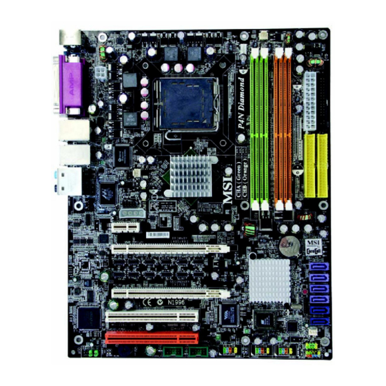
SA TA1 nvidia MCP04 SA TA3 Secondary (x1/ x8) PCI E2 SA TA4 SA TA5 PCI1 Creative SA TA6 VT6306 Sound Bluster Silicon SYSFAN1 Image PCI2 JUSB1 JUSB2 JUSB3 JFP2 JAUD1 J1394_1 J1394_2 P4N Diamond (MS-7160 v1.X) ATX Mainboard E-1-7... -
Page 13: Packing Contents
M S-7160 ATX M ainboard Packing Contents SATA RAID Driver Diskette/ Creative MSI Driver/Utility CD Audio Driver MSI motherboard External SATA 2 Cable SATA Cable/ D-Bracket 2 (Optional) Power Cable (Optional) (Optional) Round Cable of Round Cable of 1394 Cable... -
Page 14: Msi Special Feature
Getting Started MSI Special Feature Core Cell Chip By diagnosing the current system utilization, the CoreCell™ Chip automatically tunes your motherboard to the optimal state, leading to less noise, longer duration, more power-saving and higher performance. Features of CoreCell™ Speedster -- Advanced O.C. - Page 15 M S-7160 ATX M ainboard D.O.T. Express(2 generation of D.O.T.) Dynamic Overclocking by REAL CPU Loading † CoreCell chip detects CPU current as trigger point † Fastest Response Time to report REAL CPU Loading: - 1us response time, 5 times faster than competitor’s solution (by CPU VID, 5us response time.
-
Page 16: Hardware Setup
Hardware Setup Chapter 2. Hardware Setup Hardware Setup This chapter tells you how to install the CPU, memory modules, and expansion cards, as well as how to setup the jumpers on the mainboard. Also, it provides the instructions on connecting the periph- eral devices, such as the mouse, keyboard, etc. -
Page 17: Quick Components Guide
M S-7160 ATX M ainboard Quick Components Guide CPU, E-2-3 CPUFAN1, NBFAN1, E-2-16 PWR1, E-2-16 PWRFAN1, E-2-16 E-2-10 DDR DIMMs, E-2-7 Back Panel FDD1, E-2-16 I/O, E-2-12 ATX1, E-2-10 JCI1, E-2-17 JIR1, E-2-20 IDE1/2,E-2-17 JDB1, E-2-21 JCD1,E-2-20 JPWR1, E-2-10 SW1, PCI_E3, E-2-25 E-2-26... -
Page 18: Introduction To Lga 775 Cpu
CPU, make sure to install the cooler to prevent overheating. If you do not have the CPU cooler, contact your dealer to purchase and install them before turning on the computer. For the latest information about CPU, please visit http://www.msi.com.tw/ program/products/mainboard/mbd/pro_mbd_cpu_support.php. MSI Reminds You... - Page 19 MSI Reminds You... 1. Confirm if your CPU cooler is firmly installed before turning on your system. 2. Do not touch the CPU socket pins to avoid damaging.
- Page 20 Hardware Setup 5. The CPU socket has a plastic cap on 6. Remove the cap from lever hinge side it to protect the contact from damage. (as the arrow shows). The pins of Before you have installed the CPU, socket reveal. always cover it to protect the socket pin.
- Page 21 CPU. MSI Reminds You... 1. Check the information in PC Health Status in BIOS (Chapter 3) for the CPU temperature. 2. Whenever CPU is not installed, always protect your CPU socket pin with the plastic cap covered (shown in step 5) to avoid damaging.
-
Page 22: Introduction To Ddr2 Sdram
DDR2 memory module in the DDR2 slot (DIMM1~DIMM4). Otherwise, you are not able to boot up your system and your mainboard might be damaged. For the updated supporting memory modules, please visit http://www.msi. com.tw/program/products/mainboard/mbd/pro_mbd_trp_list.php. DIMM1~4... -
Page 23: Dimm Module Combination
256MB~4GB 256MB~4GB 256MB~4GB 1GB~16GB MSI Reminds You... - Please select the identical memory modules to install on the dual channel, and DO NOT install three memory modules on three DIMMs, or it may cause some failure. - Always insert the memory modules into the GREEN slots first, and it is strongly recommended not to insert the memory modules into the ORANGE slots while the GREEN slots are left empty. -
Page 24: Installing Ddr2 Modules
3. The plastic clip at each side of the DIMM slot will automatically close. Notch Volt MSI Reminds You... You can barely see the golden finger if the module is properly in- serted in the socket. E-2-9... -
Page 25: Power Supply
SIGNAL JPWR1 +12V MSI Reminds You... 1. These two connectors connect to the ATX power supply and have to work together to ensure stable operation of the mainboard. 2. Power supply of 450 watts (and above) is highly recommended for system stability. -
Page 26: Important Notification About Power Issue
Hardware Setup Important Notification about Power Issue NForce chipset is very sensitive to ESD (Electrostatic Discharge), therefore this issue mostly happens while the users intensively swap memory modules under S5 (power-off) states, and the power code is plugged while installing modules. Due to several pins are very sensitive to ESD, so this kind of memory-replacement actions might cause system chipset unable to boot. -
Page 27: Back Panel
M S-7160 ATX M ainboard Back Panel The back panel provides the following connectors: L-In RS-Out Parallel M ou se 1394 Port SPDIF USB Ports L-Out CS-Out Keyboard COM Port SPDIF Out (Coaxial) (Optical) Mouse Connector (Green) / Keyboard Connector (Purple) ®... -
Page 28: Serial Port Connector
Hardware Setup Serial Port Connector The mainboard offers one 9-pin male DIN connector as the serial port. The port is a 16550A high speed communication port that sends/receives 16 bytes FIFOs. You can attach a serial mouse or other serial devices directly to the connector. Pin Definition 1 2 3 4 5 SIGNAL... -
Page 29: Audio Port Connectors
M S-7160 ATX M ainboard LAN (RJ-45) Jack The mainboard provides 2 standard RJ-45 jacks for connection to single Local Area Network (LAN). This Giga-bit LAN enables data to be transferred at 1000, 100 or 10Mbps. You can connect a network cable to either LAN jack. Giga-bit LAN Pin Definition SIGNAL DESCRIPTION... - Page 30 Hardware Setup Parallel Port Connector: LPT1 The mainboard provides a 25-pin female centronic connector as LPT. A parallel port is a standard printer port that supports Enhanced Parallel Port (EPP) and Ex- tended Capabilities Parallel Port (ECP) mode. Pin Definition SIGNAL DESCRIPTION STROBE...
- Page 31 NBF AN1 CPUFAN1 PW RFAN1 SYSFAN1 MSI Reminds You... 1. Always consult the vendors for proper CPU cooling fan. 2. CPUFAN1 supports fan control. You can install Core Center util- ity that will automatically control the CPU fan speed according to the actual CPU temperature.
- Page 32 IDE2 (Secondary IDE Connector) IDE2 can also connect a Master and a Slave drive. MSI Reminds You... If you install two hard disks on cable, you must configure the second drive to Slave mode by setting its jumper. Refer to the hard disk documentation supplied by hard disk vendors for jumper setting instructions.
- Page 33 (Optional) You have to connect the SATA device which has own independent power supply. MSI Reminds You... Please do not fold the serial ATA cable in a 90-degree angle, which will cause the loss of data during the transmission. E-2-18...
-
Page 34: Front Panel Connectors: Jfp1/2
Left channel audio signal to front panel AUD_RET_L Left channel audio signal return from front panel MSI Reminds You... If you don’t want to connect to the front audio header, pins 5 & 6, 9 & 10 have to be jumpered in order to have signal output directed to the rear audio ports. - Page 35 Connected to JUSB1, JUSB2, or JUSB3 (the USB pinheader in YELLOW color) USB 2.0 Bracket (Optional) MSI Reminds You... Note that the pins of VCC and GND must be connected correctly, or itmay cause some damage. IrDA Infrared Module Header: JIR1 The connector allows you to connect to IrDA Infrared module.
- Page 36 Hardware Setup IEEE 1394 Connectors: J1394_1 / J1394_2 The mainboard provides two 1394 pin headers that allow you to connect IEEE 1394 ports via an external IEEE1394 bracket. Pin Definition SIGNAL SIGNAL TPA+ TPA- Ground Ground J1394_1/ J1394_2 TPB+ TPB- Cable power Cable power Key (no pin)
- Page 37 M S-7160 ATX M ainboard D-Bracket™ 2 Connected to JDB1 (Optional) Connected to JUSB1, JUSB2 or JUSB3 LEDs (the USB pinheader in YELLOW color) D-Bracket™ 2 is an external USB bracket integrating four Diagnostic LEDs, which use graphic signal display to help users understand their system. The LEDs provide up to 16 combinations of signals to debug the system.
- Page 38 Hardware Setup Decompressing BIOS image to RAM for fast booting. Initializing Keyboard Controller. Testing VGA BIOS This will start writing VGA sign-on message to the screen. Processor Initialization This will show information regarding the processor (like brand name, system bus, etc...) Testing RTC (Real Time Clock) Initializing Video Interface This will start detecting CPU clock, checking type of video...
- Page 39 M S-7160 ATX M ainboard D-Bracket™ 2 Description Initializing Floppy Drive Controller This will initialize Floppy Drive and controller. Boot Attempt This will set low stack and boot via INT 19h. Operating System Booting E-2-24...
- Page 40 Hardware Setup Button The motherboard provides the following jumpers for you to set the computer’s function. This section will explain how to change your motherboard’s function through the use of button. Clear CMOS Button: SW1 There is a CMOS RAM on board that has a power supply from external battery to keep the system configuration data.
- Page 41 M S-7160 ATX M ainboard Slots The mainboard provides one PCI Express x 1 slot, two PCI Express x16 slots and two 32-bit PCI bus slots. PCI Express Slots: PCI_E1 (Primary)/ PCI _E2 (Secondary)/ PCI_E3 The PCI Express slots, as a high-bandwidth, low pin count, serial, intercon- nect technology, support Intel highest performance desktop platforms utilizing the Intel Pentium 4 processor with HT Technology with these platform benefits.
- Page 42 Hardware Setup SLI bridge Fig.1 MSI Reminds You... 1. Mainboard photos shown in this section are for demonstration only. The appearance of your mainboard may vary depending on the model you purchase. 2. If you intend to install only ONE graphics card, make sure that your graphics card is Installed on the PCI_E1 (Primary) slot.
-
Page 43: Pci Interrupt Request Routing
3. Restart your system and a pop-up will show in the system tray confirming that M ulti-GPU has been enabled. MSI Reminds You... If you want to remove one graphics and change the status from SLI mode to normal, make sure that you have to unclick the "MultiGPU"... -
Page 44: Bios Setup
SETUP. ² You want to change the default settings for customized features. MSI Reminds You... 1. The items under each BIOS category described in this chapter are under c ontinuous update for better s y s tem performanc e. -
Page 45: Entering Setup
M S-7160 ATX M ainboard Entering Setup Power on the computer and the system will start POST (Power On Self Test) process. W hen the message below appears on the screen, press <DEL> key to enter Setup. DEL: Setup Menu TAB: Logo F11: Boot Menu If the message disappears before you respond and you still wish to enter Setup,... -
Page 46: Control Keys
The preset Optimal Defaults of the BIOS setup program provide optimal performance settings for all devices and the system. MSI Reminds You... The items under each BIOS category described in this chapter are under continuous update for better system performance. Therefore, the description may be slightly different from the latest BIOS and should be held for reference only. -
Page 47: The Main Menu
M S-7160 ATX M ainboard The Main Menu Once you enter AMIBIOS CMOS SETUP UTILITY, the Main Menu will appear on the screen. Use arrow keys to move among the items and press <Enter> to enter the sub-menu. Cell M enu Use this menu to specify your settings for CPU/AGP frequency/voltage control and overclocking. - Page 48 BIOS Setup Load Fail-Safe Defaults Use this menu to load the default values set by the BIOS vendor for stable system performance. Load Optimized Defaults Use this menu to load the default values set by the mainboard manufacturer specifi- cally for optimal performance of the mainboard. BIOS Setting Password Use this menu to set the password for BIOS.
- Page 49 M S-7160 ATX M ainboard nVidia RAID Setup nVidia RAID Setup Press <Enter> to enter the sub-menu and the following screen appears: nVidia RAID Function This field is used to enable/disable the nVidia RAID function. W hen you set to enable and the following fileds will appear and can be selectabled.
-
Page 50: Onboard Device Configuration
BIOS Setup Onboard Device Configuration Onboard Devices Configuration Press <Enter> to enter the sub-menu and the following screen appears: Onboard LAN Controller (for Marvell 88E8053 LAN) The field enables or disables the onboard LAN controller. Setting options: [Enabled], [Disabled]. Onboard IEEE1394 Controller The field enables or disables the onboard IEEE1394 controller. -
Page 51: Pc Health Status
M S-7160 ATX M ainboard PC Health Status This section shows the status of your CPU, fan, overall system status, etc. Monitor function is available only if there is hardware monitoring mechanism onboard. Chassis Intrusion The field enables or disables the feature of recording the chassis intrusion status and issuing a warning message if the chassis is once opened. -
Page 52: Cell Menu
Cell Menu The items in Cell Menu includes some important settings of CPU, PCIE, DRAM and overclocking functions. MSI Reminds You... Change these settings only if you are familiar with the chipset. Current CPU Clock This field shows the current clocks of CPU. Read-only. - Page 53 M S-7160 ATX M ainboard CPU Ratio CMOS Setting This field shows the CPU Ratio which detected by CMOS. Read-only PCIE Frequency This field allows you to select the PCIE frequency (in MHz). Select the number be- tween [100]~[145] for needeed frequency. SLI M ode Select This fiels allows you to enable or disable the SLI mode.
- Page 54 BIOS Setup MSI Reminds You... The settings shown in different color in Adjust CPU Voltage, DDR Voltage and NB Voltage help to verify if your setting is proper for your system. G ray: Default setting. Yellow: High performance setting. Red: Not recommended setting and the system may be unstable.
- Page 55 M S-7160 ATX M ainboard [Captain] 3rd level of overclocking, increasing the memory clock by [Colonel] 4th level of overclocking, increasing the memory clock by [General] 5th level of overclocking, increasing the memory clock by 10%. [Commander] 6th level of overclocking, increasing the memory clock by 15%.
-
Page 56: Load Fail-Safe/Optimized Defaults
BIOS Setup Load Fail-Safe/Optimized Defaults The two options on the main menu allow users to restore all of the BIOS settings to the default Fail-Safe or Optimized values. The Optimized Defaults are the default values set by the mainboard manufacturer specifically for optimal performance of the mainboard. -
Page 57: Bios Setting Password
M S-7160 ATX M ainboard BIOS Setting Password W hen you select this function, a message as below will appear on the screen: Type the password, up to six characters in length, and press <Enter>. The password typed now will replace any previously set password from CMOS memory. You will be prompted to confirm the password. -
Page 58: Français
M anuel d’utilisation Manuel d’Utilisation P4N Diamond Français F - 1... - Page 59 Carte Mère ATX M S-7160 F - 2...
- Page 60 M anuel d’utilisation P4N Diamond Manuel d’Utilisation Féliciation vous venez d’acheter une carte mère ATX Diamond (MS-7160) v1.X. La P4N Diamond est basée sur le chipset ® nVIDIA nForce™4 SLI Intel Edition offrant des performances ® importantes. Elle fonctionne avec les processeurs Intel...
- Page 61 M émoire Principale † Supporte le dual channel, DDR2 400/ 533/ 667 (4* 240broches)/ 1.8V DDR2 DIMMs † Supporte un maximum de mémoire de 16GB (Pour une mise à jour sur les modules de mémoire, merci de visiter http://www.msi. com.tw/program/products/mainboard/mbd/pro_mbd_trp_list.php.) Slots †...
- Page 62 M anuel d’utilisation SATA Intégré † MCP04 supporte 4 ports SATA-II (SATA1-4). Taux de transfert jusqu’ŕ 300 MB/s. Supporte les modes RAID 0/ 1/ 0+1/ RAID 5 ou JBOD . † Silicon Image’s SATARAID supporte 2 autres ports SATA-II (SATA5/6). Taux de transfert juqu’ŕ...
- Page 63 Carte Mère ATX M S-7160 Périphériques Intégrés † Périphériques intégrés inclus: - 1 port floppy supportant 1 FDD avec 360K, 720K, 1.2M, 1.44M et 2.88Mbytes - 1 port de série (COM1) - 1 port parallčle supportant les modes SPP/EPP/ECP - 1 Audio jack(5-in-1), coaxial/fiber SPDIF out - 1 jeu de broches D-Bracket 2 - 1 jeu de broches CD-In - 3 IEEE 1394 (Arričre* 1 / Avant * 2)
- Page 64 M anuel d’utilisation Exclusivité MSI Technologie Core Cell En diagnosticant l’utilisation du systčme, la puce CoreCell™ accorde automatiquement votre carte mčre ŕ son état optimal vous apportant moins de bruit, une durée de vie plus longue et des performances plus importantes.
- Page 65 Carte Mère ATX M S-7160 D.O.T. Express(2 generation de D.O.T.) Dynamic Overclocking par REAL CPU Loading † La puce CoreCell detecte le CPU current as trigger point † Temps de réponse plus rapide to report REAL CPU Loading: - Temps de réponse 1us (by CPU VID, Temps de réponse 5us). - Slowest: Detect by Background Software Solution d’alimentation dédiée pour DRAM et Chipset †...
- Page 66 MCP04 SA TA3 Secondary (x1/ x8) PCI E2 SA TA4 SA TA5 PCI1 Creative SA TA6 VT6306 Sound Bluster Silicon SYSFAN1 Image PCI2 JUSB1 JUSB2 JUSB3 JFP2 JAUD1 J1394_1 J1394_2 Carte Mère ATX P4N Diamond (MS-7160 v1.X) F - 9...
- Page 67 Carte Mère ATX M S-7160 Connecteur d’alimentation ATX 24 broches: ATX1. Ce connecteur permet une connection ŕ l’alimentation ATX. Connecteurs d’alimentation AT X 12V: PWR1 & JPWR1. Ces deux connecteurs vous procurent une connection ŕ une alimentation 12V. Connecteur Floppy Disk Drive: FDD1. Cette carte mčre procure un connecteur standard floppy disk drive supportant les types floppy disk 360K, 720K, 1.2M, 1.44M et 2.88M.
- Page 68 M anuel d’utilisation Connecteur Front USB : JUSB1, JUSB2 & JUSB3. Cette carte mčre pro- cure 3 connecteurs standards USB2.0: JUSB1, JUSB2 & JUSB3. Connecteur audio Front Panel: JAUD1. Ce connecteur Front Panel Audio permet une connection au front panel audio. Connecteur Infra rouge IrDA : JIR1.
- Page 69 ’insère dans le c lip (c omme le montre les flèches). MSI Vous Rappelle... 1. S’assurer que le ventilateur est bien installé avant de mettre en marche le système. 2. Ne pas toucher le socket CPU pour éviter de l’endommager.
- Page 70 M anuel d’utilisation 5. Le socket CPU possède un plastique 6. Retirer la protection (comme indiqué de protection. Ne le retirer qu’au par al flèche), pour déc ouvrir les moment d’installer le CPU. broches de contact. 7. Lever le levier et ouvrir le plateua de 8.
- Page 71 à nouveau et pousser sur correctement installé. le clip pour soulever le CPU. MSI Vous Rappelle... 1. Vérifier dans le BIOS les informations de température CPU dans : PC Health Status (Chapitre 3). 2. lorsque le CPU n’est pas installé, vous devez remettre al protection sur la carte mère pour protéger le socket CPU..
- Page 72 DDR2 (DIMM1~DIMM4). Dans le cas contraire vous ne pourrez démarrer le système et la carte mère sera certainement endommagée. Pour une mise à jour sur les modules de mémoire supportés, veuillez visiter : http://www.msi.com.tw/program/products/mainboard/mbd/pro_mbd_trp_list.php. DIMM1~4 (de gauche (Vert) à...
- Page 73 256MB~4GB 256MB~4GB 256MB~4GB 1GB~16GB MSI Vous Rappelle... - Veuillez c hoisir des modules identiques pour le mode double canal et ne pas installer 3 modules sur 3 DIMM cela pourrait causer quelques problčmes. - Toujours insérer les modules de mémoire dans le slot VERT en premier, il n’est oas recommandé...
- Page 74 M anuel d’utilisation E n c o c h e Volt MSI Vous Rappelle... Vous devez généralement appercevoir le haut des broches dorée lorsque le module est correctement installédans le socket. Panneau Arrière La panneau arrière procure les connecteurs suivants :...
- Page 75 Carte Mère ATX M S-7160 Important Notification about Power Issue Le chipset NForce est très sensible à l’ESD (Décharge Eléctrostatique). Ce problème intevient la plupart du temps lorsque l’utilisateur change des modules de mémoire lorsque le pc est en veille (S5) et que l’alimentation est toujours connectée. Etant donné...
- Page 76 M anuel d’utilisation BIOS Setup Allumez votre ordinateur, le système lance le processus de POST (Power On Self Test). Quand le message ci-dessous apparaît à l’écran, appuyez sur le bouton <DEL> pour entrer dans le setup. DEL: Setup Menu TAB: Logo F11: Boot Menu Si le message disparaît avant que vous ne puissiez entrer dans le setup, redémarrez votre ordinateur en appuyant sur le bouton RESET.
-
Page 77: Getting Help
Default Settings En choisissant cette option, le BIOS s era chargé avec les valeurs par défaut optimisées. MSI Reminds You... The items under each BIOS category described in this chapter are under continuous update for better system performance. Therefore, the description may be slightly different from the latest BIOS and should be held for reference only. -
Page 78: Menu Principal
M anuel d’utilisation Menu Principal Une fois entré dans le AMIBIOS CMOS SETUP UTILITY, le menu principal apparaîtra à l’écran. Utilisez les flèches pour naviguer et <Enter> pour accéder au sous-menu. Cell M enu Utiliser ce menu pour entrer vos propres valeurs pour la fréquence/voltage CPU/AGP et ainsi réaliser nu overclocking. - Page 79 Carte Mère ATX M S-7160 Load Fail-Safe Defaults Utilisez ce menu afin de charger les valeurs définies en usine pour le BIOS, offrant ainsi des performances stables. Load Optimized Defaults Charge les paramètres optimum du BIOS sans affecter la stabilité du système. BIOS Setting Password Utilisez ce menu pour mettre un mot de passe BIOS.
- Page 80 M anuel d’utilisation nVidia RAID Setup nVidia RAID Setup Appuyez sur <Enter> pour accéder au sous-menu : nVidia RAID Function Ce paramčtre est utiliser pour activer/désactiver la fonction nVidia RAID. En position “enable” les paramčtres ci-dessous seront sélectionnables. Options: [Disabled] Désactive la fonctioin nVidia RAID En position “enabled”...
- Page 81 Carte Mère ATX M S-7160 Silicon Image RAID Setup Configuration Appuyez sur <Enter> pour accéder aux sous-menus : Onboard Silicon RAID Controller Active/désactive le contrôlleurintégré Silicon RAID. Avant d’utiliser le silicon RAID pour les disques durs, vous devez mettre en position “RAID”. Options: [Disabled] Désactive le contrôleur intégré...
- Page 82 M anuel d’utilisation Menu Cell Ce Chapitre inclus des paramètres importants sur le CPU, AGP, DRAM et les fonctions d’overclocking. MSI Vous Rappelle... Vous pouvez changer ces paramčtres uniquement si vous ętes familiarisés avec le chipset Current CPU Clock Ce champs permet de visualiser la vitesse d’horloge du CPU. Lecture uniquement.
- Page 83 Carte Mère ATX M S-7160 CPU Ratio CMOS Setting Indique le ratio CPU detecté par CMOS. Lecture uniquement PCIE Frequency Paramètre permettant de sélectionner la fréquence PCIE (en MHz). Choisir un nombre entre [100]~[145]. SLI M ode Select Ce paramètre permet d’activer/désactiver le modeSLI. Quand vous installez 2 cartes VGA identiques (geforece) et que vos activez le mode SLI, les 2 ports PCIE X16 se transforment en slots PCIE x8.
- Page 84 M anuel d’utilisation MSI Vous Rappelle... Les paramètres indiqués en différentes couleurses (Adjust CPU Voltage, DDR Voltage et NB Voltage) permettent de vérifier si les paramètres sont corrects. Gris: Paramètre par défaut. Jaune: Paramètre haute performance Rouge: Paramètre non recommandé, système instable.
- Page 85 Carte Mère ATX M S-7160 Voltage Control Function Appuyer sur <Enter> pour accéder au sous menu : CPU Spread Spectrum Ce champs est utilisé pour activer/désactiver la fonction CPU Spread Spectrum. Lors de l’ overclocking CPU, atoujours mettre en position [Disabled]. Options: [Center Spread], [Disabled].
-
Page 86: Deutsch
Benutzerhandbuch P4N Diamond Benutzerhandbuch Deutsch G - 1... - Page 87 M S-7160 ATX M ainboard G - 2...
- Page 88 Benutzerhandbuch P4N Diamond Benutzerhandbuch Danke, dass Sie das P4N Diamond (MS-7160) V1.X ATX Mainboard gewählt haben. Das P4N Diamond Mainboard basiert ® auf dem nVIDIA nForce™4 SLI Intel EditionChips atz und ermöglicht somit ein optimales und effizientes System. Entworfen, ®...
- Page 89 † Ein PCI Express x1 Slot (erfüllt die PCI Express Bus Spezifikation V1.0a) † Zwei 32-bit Master PCI Bus Slots, einschließlich eines orangefarbenen, der 2 Master für MSI PCI Karten mit Spezialfunktion bereit stellt (z.B. W ireless LAN und Bluetooth Kombikarte.).
- Page 90 Benutzerhandbuch † Unters t ützt RAID 0/ 1/ 0+1/ RAID 5 oder J BO D Betriebs modu s (ohne Raidfunktionalität). Onboard SATA † N V R A I D u n t er s t ü t z t 4 S ATA I I A n s c h l ü s s e ( S ATA 1 - 4 ) , m i t ei n er Datenübertragungsrate von bis zu 300 MB/s.
- Page 91 M S-7160 ATX M ainboard † In den Chip integrierte Realtek ALC850 Audiolösung (7.1 K Softwareaudio) (optional) - Erfüllt die Spezifikation AC’97 2.3 Peripherieanschlüsse onboard † hierzu gehören: - 1 Anschluss für 1 Diskettenlaufwerk mit 360 KB, 720 KB, 1,2 MB, 1,44 MB oder 2,88 MB.
- Page 92 Benutzerhandbuch MSI Sonderausstattung Core Cell Chip Indem die laufende Auslastung des Systems geprüft wird, stellt der CoreCell™ Chip Ihr Motherboard automatisch optimal ein, was zu weniger G eräus c hen, längerer Lebens d auer, höherer Stromersparnis und besserer Leistung führt.
- Page 93 M S-7160 ATX M ainboard D.O.T. Express (D.O.T. der 2. Generation) Dynamische Übertaktung durch REAL CPU Ladezustand † Der CoreCell Chip erkennt die CPU Spannung als Auslöser † Schnellstmögliche Reaktionszeit bei der Meldung des REAL CPU Ladezustands: - 1μs Reaktionszeit, 5 mal schneller als die Lösung des Mitbewerbs (von CPU VID, 5μs Reaktionszeit.) - Langsamste: Erkennung durch Software im Hintergrund Lösung zur dedizierten Stromversorgung für DRAM und Chipsatz...
- Page 94 MCP04 SA TA3 Secondary (x1/ x8) PCI E2 SA TA4 SA TA5 PCI1 Creative SA TA6 VT6306 Sound Bluster Silicon SYSFAN1 Image PCI2 JUSB1 JUSB2 JUSB3 JFP2 JAUD1 J1394_1 J1394_2 P4N Diamond (MS-7160 v1.X) ATX Mainboard G - 9...
- Page 95 M S-7160 ATX M ainboard ATX 24-Pin Stromanschluss: ATX1 Hier können Sie ein ATX Netzteil anschließen ATX 12V Stromanschluss: PWR1 & JPWR1 Diese zwei Stromanschlüsse werden verwendet, um die Versorgung mit Strom mit 12 zu gewährleisten. Anschluss des Diskettenlaufwerks: FDD1 Das Mainboard verfügt über einen Standardanschluss für Diskettenlaufwerke mit 360 KB, 720 KB, 1,2 MB, 1,44 MB oder 2,88 MB Kapazität.
- Page 96 Benutzerhandbuch CD- Eingang: JCD1 Hier kann das Audiokabel des CD-ROM Laufwerkes angeschlossen werden. 2 Connector: JDB1 Das Mainboard verfügt über einen JDB1 D-Bracket Anschluss, der den Anschluss der D-Bracket™ 2 ermöglicht. USB Vorderanschlüsse: JUSB1, JUSB2 & JUSB3 Das Mainboard verfügt über drei Standard- USB- 2.0- Anschlüsse in Form der Stift- Blöcke JUSB1 &...
- Page 97 Seiten zur Mitte hin drücken, wie die Pfeile es anzeigen. MSI weist darauf hin... 1. Stellen Sie sicher, dass Ihr CPU Kühler fest eingebaut ist, bevor Sie Ihr System anschalten. 2. Berühren Sie die Pins des CPU Sock els nicht, um Schaden zu vermeiden.
- Page 98 Benutzerhandbuch 5. Um die Kontakte vor Schäden zu 6. Entfernen Sie die Kappe von der Seite des Hebelgelenks her (W ie der Pfeil schützen, ist der CPU-Sockel auf zeigt). Die Pins des Sockels werden der Oberseite mit einer Plastikkappe frei gelegt. vers ehen.
- Page 99 Sie den Clip auf, um die CPU herauszuheben. MSI weist darauf hin... 1. Überprüfen Sie die Temperatur der CPU im “ PC Health Status” im BIOS (Kapitel 3). 2. Schützen Sie die Pins des CPU Sockels stets vor Schaden (wie gezeigt in Schritt 5), indem Sie sie mit der Plastikkappe abdecken, immer wenn keine CPU installiert ist.
- Page 100 Benutzerhandbuch Speicher Das Mainboard bietet 4 Sockel für 240-pin DDR2 DIMMs, und unterstützt den Speicherausbau auf bis zu 16GB. Da DDR2 und DDR1 Module nicht untereinander austauschbar sind und der DDR2 Standard nicht rückwärtskompatibel ist, sollten Sie stets ein DDR2 Speichermodul in den DDR2 Sockel eingesetzt werden.
- Page 101 M S-7160 ATX M ainboard DIMM Speicherzusammensetzung Setzen Sie mindestens ein Speichermodul in einen Stecksockel. Jeder DIMM Sockel unterstützt einen Speicherriegel mit maximal 4 GB. Gemäß Ihren Anforderungen können Sie entweder ein- oder doppelseitige Module verwenden. Beachten Sie bitte, dass jedes DIMM als Einkanal DDR2 Modul funktionieren kann, dass jedoch bestimmte R egeln beachtet w erde n müssen, w enn Zw eik anal DDR 2 ve rw en det w er den soll (B itt e en tnehmen S ie d ie vor ges c hl agen e D DR Zusammensetzung der Tabelle unten).
-
Page 102: Hinteres Anschlusspaneel
Benutzerhandbuch Kerbe Volt MSI weist darauf hin... Die goldenen Kontakte sind kaum noch sichtbar, wenn die Module richtig eingesetzt sind. Hinteres Anschlusspaneel Das hintere Anschlusspaneel verfügt über die folgenden Anschlüsse: L-In RS-Out Parallel M aus 1394 Port SPDIF USB Ports... - Page 103 M S-7160 ATX M ainboard Wichtiger Hinweis in Bezug auf Probleme mit der Stromversorgung Der NForce Chipsatz ist gegenüber statischen Entladungen sehr empfindlich, deswegen kommt es zu diesem Problem vornehmlich, wenn der Nutzer häufig Speichermodule im Modus S5 (Strom aus) austauscht, und das Stromkabel während des Tausc hes eingesteckt is t.
-
Page 104: Selecting The First Boot Device
Benutzerhandbuch BIOS Setup Nach dem Einschalten beginnt der Computer den POST (Power On Self Test - Selbstüberprüfung nach Anschalten). Sobald die Meldung unten erscheint, drücken Sie die Taste <Entf>(<Del>) um das Setup aufzurufen. DEL: Setup Menu TAB: Logo F11: Boot Menu W enn die Nachricht verschwindet, bevor Sie reagieren und Sie möchten immer noch ins Setup, starten Sie das System neu, indem Sie es erst AUS- und danach wieder ANSCHALTEN, oder die “RESET”-Taste am Gehäuse betätigen. - Page 105 Werkseinstellungen. Die Voreinstellung “Optimal Defaults” des BIOS stellt die besten Leistungseinstellungen für all Komponenten und das System zur Verfügung. MSI weist darauf hin... Die Menüpunkte jeder in diesem Kapitel beschriebenen BIOS Kategorie befinden sich in permanenter Weiterentwicklung um die Systemleistung zu verbessern.
- Page 106 Benutzerhandbuch Hauptmenü Nachdem Sie das AMIBIOS CMOS Setup Utility aufgerufen haben, erscheint das Hauptmenü. Verwenden Sie die Pfeiltasten, um im Menü zu navigieren und drücken Sie die Eingabetaste <Enter>, um ein Untermenü aufzurufen. Cell M enu Hier können Sie Einstellungen an Frequenz/Spannung von CPU/AGP und zur Übertaktung vornehmen.
- Page 107 M S-7160 ATX M ainboard PC Health Status Dieser Eintrag gibt den Systemstatus wieder. Load Fail-Safe Defaults In diesem Menü können Sie die werkseitigen Einstellungen des BIOS Lieferanten für einem stabilen Betrieb laden. Load Optimized Defaults In diesem Menü können Sie die werkseitigen Einstellungen des Mainboardherstellers für den leistungsoptimierten Betrieb laden.
- Page 108 Benutzerhandbuch nVidia RAID Setup nVidia RAID Setup Mit <Eingabetaster> rufen Sie das folgende Untermenü auf: nVidia RAID Function Hier wird die nVidia RAID Funktion ein-/ bzw. ausgeschaltet. In der Einstellung “Enabled”(aktiviert) werden die folgenden Felder sichtbar und können ausgewählt werden. Mögliche Einstellungen: [Disabled] Schaltet die nVidia RAID Funktion aus...
- Page 109 M S-7160 ATX M ainboard Silicon Image RAID Setup Onboard Devices Configuration Mit <Eingabetaster> rufen Sie das folgende Untermenü auf: Onboard Silicon RAID Controller Hier wird der onboard Silicon RAID Kontroller ein- oder ausgeschaltet. Bevor Sie Silicon RAID für Festplatten verwenden können, müssen Sie hier zunächst “RAID” einstellen.
- Page 110 Benutzerhandbuch Cell Menu Hier können Sie einige wichtige Einstellungen bezüglich Frequenz und Spannung von CPU, PCIE, DRAM sowie zur Übertaktung vornehmen. MSI weist darauf hin... Ändern Sie diese Einstellungen nur, wenn Sie mit diesem Chipsatz vertraut sind. Current CPU Clock Gibt den derzeitigen CPU Takt an.
- Page 111 M S-7160 ATX M ainboard CPU Ratio CMOS Setting Zeigt den CPU Taktmultiplikator an, wie ihn das CMOS erkennt. Nur Anzeige. PCIE Frequency Gestattet die Wahl der PCIE Frequenz (in MHz). Geben Sie eine Zahlenwert zwischen [100]~[145] an, um die benötigte Frequenz festzulegen. SLI M ode Select Erlaubt den SLI Modus ein- oder auzuschalten.
- Page 112 Benutzerhandbuch MSI weist darauf hin... Die unterschiedliche Farbgebung der Punkte Adjust CPU Voltage, DDR Voltage und NB Voltage hilft Ihnen zu überprüfen, ob Ihre Einstellungen für Ihr System angemessen sind. G rau: Voreinstellung. Gelb: Hochleistungseinstellung. Rot: Nicht empfehlenswerte Einstellung, das System kann instabil sein.
- Page 113 M S-7160 ATX M ainboard NV4X M emory clock Overclocking Gestattet die Übertaktung des Speichers der Grafikkarte in Prozent. Mögliche Einstellungen: [Disabled] Disable this function 1. Übertaktungsebene, Steigerung des Speichertaktes um 1%. [Private] 2. Übertaktungsebene, Steigerung des Speichertaktes um 3%. [Sergeant] 3.