Table of Contents
Advertisement
Advertisement
Table of Contents

Related Manuals for MSI RS480M


Summary of Contents for MSI RS480M
- Page 1 RS480M/ RS482M MS-7145 (v2.X) M-ATX Mainboard G52-M7145X2...
- Page 2 Manual Rev: 2.1 Release Date: Aug. 2005 FCC-B Radio Frequency Interference Statement This equipment has been tested and found to comply with the limits for a class B digital device, pursuant to part 15 of the FCC rules. These limits are designed to provide reasonable protection against harmful interference in a residential installation.
-
Page 3: Copyright Notice
This device complies with Part 15 of the FCC Rules. Operation is subject to the following two conditions: (1) this device may not cause harmful interference, and (2) this device must accept any interference received, including interference that may cause undesired operation Copyright Notice T he material in this document is the intellec tual property of M ICRO-STAR INTERNATIONAL. -
Page 4: Technical Support
Alternatively, please try the following help resources for further guidance. † Visit the MSI homepage & FAQ site for technical guide, BIOS updates, driver updates, and other information: http://www.msi.com.tw & http://www.msi. -
Page 5: Weee Statement
WEEE Statement... -
Page 8: Table Of Contents
Chapter 1. Getting Started ..................1-1 Mainboard Specifications ................... 1-2 Mainboard Layout ....................1-5 Packing Checklist ....................1-6 MSI Special Feature .................... 1-7 PC Alert™ 4 ....................1-7 Live Update ....................1-8 Chapter 2. Hardware Setup .................. 2-1 Quick Components Guide ................... 2-2 Central Processing Unit: CPU ................ - Page 9 ATA133 Hard Disk Connectors: IDE1 & IDE2 ........... 2-16 Serial ATA Connectors: SATA1~SATA4 ........... 2-17 Front Panel Audio Connector: JAUDIO1 ..........2-18 Serial Port Header: JCOM2 (Optional) ............. 2-18 CD-In Connector: JCD_IN1 ................ 2-19 SPDIF-Out Connector: JSP1 (Optional) ............ 2-19 IrDA Infrared Module Header: JIR1 ............
- Page 10 SATA RAID Features ................... 4-2 Disk Striping (RAID 0) .................. 4-2 Disk Mirroring (RAID 1) ................4-3 Creating RAID Sets ..................... 4-4 BIOS RAID Utility Screen Description ............4-5 Description of RAID Setup Operations ............4-5 Installing RAID Drivers (for Windows 2000/XP only) ........4-8 Installing RAID Drivers during OS Install ............
-
Page 11: Chapter 1. Getting Started
Getting Started Ch ap ter 1 . Get ti ng Started Getting Started Thank you for choosing the RS480M/ RS482M Series (MS- 7145 v2.X) Micro ATX mainboard. The RS480M/ RS482M Series ® ® mainboards are based on ATi RS480/ RS482 & ATi SB400 chipsets ®... -
Page 12: Mainboard Specifications
Mainboard Specifications † Supports 64-bit AMD ® Athlon 64 and Sempron processor (Socket 754) † Supports up to 3700+ Athlon 64, or higher CPU (For the latest information about CPU, please visit http://www.msi.com.tw/pro- gram/products/mainboard/mbd/pro_mbd_cpu_support.php) Chipset † ATI ® RS480/ RS482 Chipset... - Page 13 Getting Started MSI Reminds You... 1. Please note that users cannot install OS, either WinME or Win98, in their SATA hard drives. Under these two OSs, SATA can only be used as an ordinary storage device. 2. To create a bootable RAID volume for a Windows 2000 environment, Microsoft’s Windows 2000 Service Pack 4 (SP4) is required.
- Page 14 The 1394 GUID address is burnt in the BIOS core. If the 1394 GUID address is lost due to an unpredictable event, such as replac- ing a new BIOS chip, users can use the utility from MSI’s website by entering the 1394 GUID address to recover its original one.
-
Page 15: Mainboard Layout
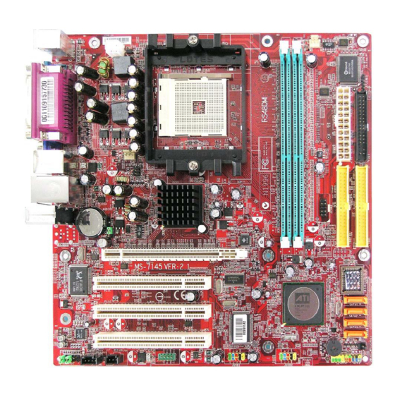
JTV1 (optional) Top: LAN Jack Bottom: USB ports RS480/RS482 Line-In BATT JCOM2 Line-Out JBAT1 (optional) PCIE16X1 PCI1 PCI2 SB400 PCI3 VT6307 ALC655 JCASE1 JUSB1 JUSB2 JAUDI01 JCD_IN1 JSP1(optional) J1394_1 (optional) JBIOS_WP1 JFP2 JFP1 RS480M/ RS482M Series (MS-7145 v2.X) M-ATX Mainboard... -
Page 16: Packing Checklist
MS-7145 M-ATX Mainboard Packing Checklist MSI Driver/Utility CD SATA Cable (Optional) MSI motherboard Round Cable of Round Cable of Power Cable Floppy Disk IDE Devices 1394 Bracket (Optional) USB Bracket (Optional) Back IO Shield * The pictures are for reference only and may... -
Page 17: Msi Special Feature
Getting Started MSI Special Feature PC Alert™ 4 The PC Alert 4 is a utility you can find in the CD-ROM disk. The utility is just like your PC doctor that can detect the following PC hardware status during real time operation: ö... -
Page 18: Live Update
W eb site. To use the function, you need to install the “MSI Live Update 3” application. After the installation, the “MSI Live Update 3” icon (as shown on the right) will appear on the screen. Double click the “MSI Live Update 3” icon, and the following screen will appear: Several buttons are placed on the left column of the screen. -
Page 19: Chapter 2. Hardware Setup
Hardware Setup Chapter 2. Hardware Setup Hardware Setup This chapter tells you how to install the CPU, memory modules, and expansion cards, as well as how to setup the jumpers on the mainboard. Also, it provides the instructions on connecting the pe- ripheral devices, such as the mouse, keyboard, etc. -
Page 20: Quick Components Guide
MS-7145 M-ATX Mainboard Quick Components Guide JPW1, p.2-9 DDR DIMMs, p.2-7 CPU, p.2-3 SYSFAN1, CPUFAN1, p.2-15 p.2-15 Back Panel ATX1, p.2-9 I/O, p.2-10 W83627THF JIR1, p.2-19 FDD1, p.2-15 JTV1, p.2-22 JBAT1, p.2-23 PCI Express IDE1/2, p.2-16 Slot, p.2-24 PCI Slots, p.2-24 SATA1~4, p.2-13... -
Page 21: Central Processing Unit: Cpu
If you do not have the heat sink and cooling fan, contact your dealer to purchase and install them before turning on the computer. For the latest information about CPU, please visit http://www.msi.com.tw/pro- gram/products/mainboard/mbd/pro_mbd_cpu_support.php. MSI Reminds You... -
Page 22: Cpu Installation Procedures For Socket 754
MS-7145 M-ATX Mainboard CPU Installation Procedures for Socket 754 1. Please turn off the power and unplug the power cord before O pen Lever installing the CPU. Sl i di ng 90 degree Pl at e 2. Pull the lever s ideways away from the socket. -
Page 23: Installing Amd Athlon64 Cpu Cooler Set
Hardware Setup Installing AMD Athlon64 CPU Cooler Set W hen you are installing the CPU, make sure the CPU has a heat sink and a cooling fan attached on the top to prevent overheating. If you do not have the heat sink and cooling fan, contact your dealer to purchase and install them before turning on the computer. - Page 24 7. Locate the Fix Lever, Safety Hook and the Fixed Bolt. Lift up the in- tensive fixed lever. MSI Reminds You... While disconnecting the Safety Hook from the fixed bolt, it is necessary to keep an eye on Safety Hook...
-
Page 25: Memory
Install at least one DIMM module on the slots. Each DIMM slot supports up to a maximum size of 1GB. Users can install either single- or double-sided modules to meet their own needs. MSI Reminds You... - This mainboard DO NOT support the memory module installed with more than 18 pieces of IC (integrated circuit). -
Page 26: Installing Ddr Modules
MS-7145 M-ATX Mainboard Installing DDR Modules The DDR DIMM has only one notch on the center of module. The module will only fit in the right orientation. Insert the DIMM memory module vertically into the DIMM slot. Then push it in until the golden finger on the memory module is deeply inserted in the socket. -
Page 27: Power Supply
Pin Definition JPW1 SIGNAL MSI Reminds You... 1. These two connectors connect to the ATX power supply and have to work together to ensure stable operation of the mainboard. 2. Power supply of 350 watts (and above) is highly recommended for system stability. -
Page 28: Back Panel
MS-7145 M-ATX Mainboard Back Panel L-In Parallel (optional) M ou se 1394 Port L-Out Keyboard VGA Port COM Port USB Ports Mouse/Keyboard Connector ® The mainboard provides a standard PS/2 mouse/keyboard mini DIN connec- ® ® tor for attaching a PS/2 mouse/keyboard. -
Page 29: Serial Port Connector
Hardware Setup Serial Port Connector The mainboard offers one 9-pin male DIN connector as the serial port. The port is a 16550A high speed communication port that sends/receives 16 bytes FIFOs. You can attach a serial mouse or other serial devices directly to the connector. Pin Definition 1 2 3 4 5 SIGNAL... -
Page 30: Ieee1394 Port
MS-7145 M-ATX Mainboard IEEE 1394 Port (Optional) The back panel provides one standard IEEE 1394 port. The standard IEEE1394 port connects to IEEE1394 devices without external power. The IEEE1394 high- speed serial bus complements USB by providing enhanced PC connectivity for a wide range of devices, including consumer electronics audio/video (A/V) appliances, storage peripherals, other PCs, and portable devices. -
Page 31: Lan Jack: 10/100 Lan (8100C) /Giga-Bit Lan (8110S)(Optional)2-13
Hardware Setup RJ-45 LAN Jack: 10/100 LAN (8100C) /Giga-bit LAN (8110S) (Optional) The mainboard provides two standard RJ-45 jacks for connection to Local Area Network (LAN). Giga-bit LAN enables data to be transferred at 1000, 100 or 10Mbps. You can connect a network cable to either LAN jack. Activity Indicator Link Indicator RJ-45 LAN Jack... -
Page 32: Parallel Port Connector: Lpt1
MS-7145 M-ATX Mainboard Parallel Port Connector: LPT1 The mainboard provides a 25-pin female centronic connector as LPT. A parallel port is a standard printer port that supports Enhanced Parallel Port (EPP) and Extended Capabilities Parallel Port (ECP) mode. Pin Definition SIGNAL DESCRIPTION STROBE... -
Page 33: Connectors
CPU fan control. +1 2V +1 2V SENSOR SENSOR CPUFAN1 SYSFAN1 MSI Reminds You... ® Please refer to the recommended CPU fans at AMD official website or consult the vendors for proper CPU cooling fan. 2-15... -
Page 34: Ata133 Hard Disk Connectors: Ide1 & Ide2
IDE2 (Secondary IDE Connector) IDE2 can also connect a Master and a Slave drive. MSI Reminds You... If you install two hard disks on cable, you must configure the second drive to Slave mode by setting its jumper. Refer to the hard disk docu- mentation supplied by hard disk vendors for jumper setting instructions. -
Page 35: Serial Ata Connectors: Sata1~Sata4
Serial ATA cable Take out the dust cover and connect to the hard disk devices Connect to SATA1/2/3/4 MSI Reminds You... Please do not fold the Serial ATA cable into 90-degree angle. Otherwise, data loss may occur during transmission. 2-17... -
Page 36: Front Panel Audio Connector: Jaudio1
Left channel audio signal to front panel AUD_RET_L Left channel audio signal return from front panel MSI Reminds You... If you don’t want to connect to the front audio header, pins 5 & 6, 9 & 10 have to be jumpered in order to have signal output directed to the rear audio ports. -
Page 37: Cd-In Connector: Jcd_In1
Hardware Setup CD-In Connector: JCD_IN1 This connector is provided for CD-ROM audio. JCD_IN1 SPDIF-Out Connector: JSP1 (Optional) This connector is used to connect SPDIF (Sony & Philips Digital Interconnect Format) interface for digital audio transmission. JSP1 SPDIF Connected to JSP1 SPDIF Bracket (Optional) IrDA Infrared Module Header: JIR1 (Optional) The connector allows you to connect to IrDA Infrared module. -
Page 38: Front Panel Connectors: Jfp1/ Jfp2
MS-7145 M-ATX Mainboard Front Panel Connectors: JFP1/ JFP2 The mainboard provides two front panel connectors for electrical connection ® to the front panel switches and LEDs. JFP1 is compliant with Intel Front Panel I/O Connectivity Design Guide. JFP1 Pin Definition SIGNAL DESCRIPTION HD_LED_P... -
Page 39: Ieee 1394 Connectors: J1394_1 (Optional)
Hardware Setup MSI Reminds You... Note that the pins of VCC and GND must be connected correctly to avoid possible damage. IEEE 1394 Connectors: J1394_1 (Optional) The mainboard provides one 1394 pin header that allows you to connect IEEE 1394 ports via an external IEEE1394 bracket (optional). -
Page 40: Tv-Out Connector: Jtv1 (Optional)
MS-7145 M-ATX Mainboard TV-Out Connector: JTV1 (Optional) The mainboard optionally provides a TV-Out connector for you to attach a TV- Out bracket. The TV-Out bracket offers two types of TV-Out connectors: S-Video and RCA Composite connector. Select the appropriate one to connect to the televi- sion and the television will be able to display PC’s information. -
Page 41: Jumpers
JBAT1 Keep Data Clear Data MSI Reminds You... You can clear CMOS by shorting 2-3 pin while the system is off. Then return to 1-2 pin position. Avoid clearing the CMOS while the system is on; it will damage the mainboard. -
Page 42: Slots
MS-7145 M-ATX Mainboard Slots The motherboard provides one PCI Express x16 slot and three 32-bit PCI bus slots. PCI Express Slots The PCI Express slot, as a high-bandwidth, low pin count, serial, interconnect technology, supports Intel highest performance desktop platforms utilizing the Intel Pentium 4 processor with HT Technology. -
Page 43: Chapter 3. Bios Setup
SETUP. ² You want to change the default settings for customized features. MSI Reminds You... 1. The items under each BIOS category described in this chapter are under c ontinuous update for better s y s tem performanc e. -
Page 44: Entering Setup
MS-7145 M-ATX Mainboard Entering Setup Power on the computer and the system will start POST (Power On Self Test) process. W hen the message below appears on the screen, press <DEL> key to enter Setup. DEL: Setup Menu TAB: Logo F11: Boot Menu If the message disappears before you respond and you still wish to enter Setup, restart the system by turning it OFF and On or pressing the RESET button. -
Page 45: Control Keys
The preset Optimal Defaults of the BIOS setup program provide optimal performance settings for all devices and the system. MSI Reminds You... The items under each BIOS category described in this chapter are under continuous update for better system performance. Therefore, the description may be slightly different from the latest BIOS and should be held for reference only. -
Page 46: The Main Menu
MS-7145 M-ATX Mainboard The Main Menu Once you enter AMIBIOS CMOS SETUP UTILITY, the Main Menu will appear on the screen. Use arrow keys to move among the items and press <Enter> to enter the sub-menu. Standard CMOS Features Use this menu for basic system configurations, such as time, date etc. Advanced BIOS Features ®... - Page 47 BIOS Setup Load Fail-Safe Defaults Use this menu to load the default values set by the BIOS vendor for stable system performance. Load Optimized Defaults Use this menu to load the default values set by the mainboard manufacturer specifi- cally for optimal performance of the mainboard. BIOS Setting Password Use this menu to set the password for BIOS.
-
Page 48: Standard Cmos Features
MS-7145 M-ATX Mainboard Standard CMOS Features The items in Standard CMOS Features Menu includes some basic setup items. Use the arrow keys to highlight the item and then use the <PgUp> or <PgDn> keys to select the value you want in each item. Date (MM:DD:YY) This allows you to set the system to the date that you want (usually the current date). - Page 49 BIOS Setup Dev ice This item shows the information about the specified item. Read-only. LBA/Large M ode This item allows you to enable or disable the LBA (Logical Block Address, the logical block size in hard disk) mode. Setting options: [Auto], [Disabled]. DM A M ode This item allows you to enable or disable the DMA (Direct Memory Access) mode.
-
Page 50: Advanced Bios Features
MS-7145 M-ATX Mainboard Advanced BIOS Features Quick Booting Setting the item to [Enabled] allows the system to boot within 5 seconds since it will skip some check items. Available options: [Enabled], [Disabled]. Boot Sector Protection This function protects the BIOS from accidental corruption by unauthorized users or computer viruses. - Page 51 Press “Enter” and you will see the sub-menu that shows you the Hard Disk / Removable & CD/DVD devices information. Read-only. MSI Reminds You... Available settings for “1st/2nd/3rd Boot Device” vary depending on the bootable devices you have installed. For example, if you did not...
-
Page 52: Advanced Chipset Features
MS-7145 M-ATX Mainboard Advanced Chipset Features M CT Timing M ode This field has the capacity to automatically detect all of the DRAM timing. If you set this field to [SPD], the following field will be selectable. The settings are: [Auto], [SPD]. CAS Latency (CL) W hen the MCT Timing Mode is set to [Manual], the field is adjustable. -
Page 53: Integrated Peripherals
BIOS Setup Integrated Peripherals USB Controller The field is used to enable/disable the onboard USB controller. Setting options: [Disabled], [Enabled]. USB Device Legacy Support Set to [Enabled] if you need to use any USB 1.1/2.0 device in the operating system that does not support or have any USB 1.1/2.0 driver installed, such as DOS. - Page 54 MS-7145 M-ATX Mainboard On-Chip IDE Controller This field allows you to enable or disable on-chip IDE Controller. Settings options: [Disabled], [Primary], [Secondary], [Both]. PCI IDE BusM aster Set this option to [Enabled] to specify that the IDE controller on the PCI local bus has bus mastering capability.
- Page 55 BIOS Setup Parallel Port M ode This item selects the operation mode for the onboard parallel port. Setting options: [ECP], [Normal] or [Bi-Directional]. SATA Devices Configuration Press <Enter> to enter the sub-menu and the following screen appears: OnChip SATA Channel This field allows you to enable or disabled the SATA controllers.
-
Page 56: Power Management Setup
MS-7145 M-ATX Mainboard Power Management Setup MSI Reminds You... S3-related functions described in this section are available only when your BIOS supports S3 sleep mode. ACPI Function This item is to activate the ACPI (Advanced Configuration and Power Management Interface) Function. If your operating system is ACPI-aware, such as Windows 98SE/ 2000/ME/XP, select [Enabled]. - Page 57 BIOS Setup Suspend Time Out (M inute) If system activity is not detected for the length of time specified in this field, all devices except CPU will be shut off. Setting options: [Disabled], [1], [2], [3], [4], [5], [10], [15], [32], [64]. Power Button Function This feature allows users to configure the Power Button function.
- Page 58 MS-7145 M-ATX Mainboard Resume by PCI Device (PME#) This controls how and whether the system can be powered on by the devices installed on PCI/PCI-E slots. Setting options: [Disabled], [Enabled]. Resume by RTC Alarm This is used to enable or disable the feature of booting up the system on a scheduled time/date from the S3, S4, and S5 power off state.
-
Page 59: Pnp/Pci Configurations
BIOS Setup PNP/PCI Configurations This section describes configuring the PCI bus system and PnP (Plug & Play) feature. PCI, or Peripheral Component Interconnect, is a system which allows I/O devices to operate at speeds nearing the speed the CPU itself uses when communi- cating with its special components. - Page 60 MS-7145 M-ATX Mainboard IRQ Resource Setup Press <Enter> and the following sub-menu appears. IRQ 3/4/5/7/9/10/11/14/15 These items specify the bus where the specified IRQ line is used. The settings determine if AMIBIOS should remove an IRQ from the pool of avail- able IRQs passed to devices that are configurable by the system BIOS.
-
Page 61: H/W Monitor
BIOS Setup H/W Monitor This section shows the status of your CPU, fan, overall system status, etc. Monitor function is available only if there is hardware monitoring mechanism onboard. CPU Shutdown Temperature If the CPU temperature reaches the upper limit preset in this setting, the system will be shut down automatically. - Page 62 MS-7145 M-ATX Mainboard PC Health Status Press <Enter> and the following sub-menu appears. CPU/System Temperature, CPU/SYSTEM FAN Speed, Vcore, +3.3 V, +5.0 V, +12.0V, +5VSB, Battery These items display the current status of all of the monitored hardware devices/ components such as CPU voltages, temperatures and all fans’ speeds. 3-20...
-
Page 63: Cell Menu
BIOS Setup Cell Menu The items in Cell Menu includes some important settings of CPU, PCIE, DRAM. MSI Reminds You... Change these settings only if you are familiar with the chipset. Current CPU Clock This field shows the current clocks of CPU. Read-only. - Page 64 EMI generated by modulating the pulses so that the spikes of the pulses are reduced to flatter curves. Setting options: [Disabled], [Enabled]. MSI Reminds You... 1. If you do not have any EMI problem, leave the setting at [Disabled] for optimal system stability and performance.
-
Page 65: Load Fail-Safe/Optimized Defaults
BIOS Setup Load Fail-Safe/Optimized Defaults The two options on the main menu allow users to restore all of the BIOS settings to the default Fail-Safe or Optimized values. The Optimized Defaults are the default values set by the mainboard manufacturer specifically for optimal performance of the mainboard. -
Page 66: Bios Setting Password
MS-7145 M-ATX Mainboard BIOS Setting Password W hen you select this function, a message as below will appear on the screen: Type the password, up to six characters in length, and press <Enter>. The password typed now will replace any previously set password from CMOS memory. You will be prompted to confirm the password. -
Page 67: Chapter 4. Ati Sata Raid Setup Guide
ATI SATA RAID Setup Guide Chapter 4. ATI SATA RAID Setup Guide ATI SATA RAID Setup Guide Two major challenges facing the storage industry today are (1): keep pace with increasing performance demands of computer systems by im proving disk I/O throughput, and (2): provide data accessibility in the event of hard disk failure. -
Page 68: Sata Raid Features
MS-7145 M-ATX Mainboard SATA RAID Features u RAID 0 and RAID 1 u On-line Mirror Rebuilding u RAID GUI Monitoring Utility: - Displays/Logs/Alerts Users to Vital RAID Set Information - Manages RAID Set Functions (configures, rebuilds, etc.) u RAID Set accommodates multiple size HDDs u HDDs function normally when not in RAID Sets u Adjustable stripe size for RAID 0 u Automatically selects highest available transfer speed for all ATA and ATAPI... -
Page 69: Disk Mirroring (Raid 1)
ATI SATA RAID Setup Guide Disk Mirroring (RAID 1) Disk mirroring creates an identical twin for a selected disk by having the data simul- taneously written to two disks. This redundancy provides protection from a single disk failure. If a read failure occurs on one drive, the system reads the data from the other drive. -
Page 70: Creating Raid Sets
MS-7145 M-ATX Mainboard Creating RAID Sets Creating and deleting RAID sets and performing other RAID setting up operations are done in the BIOS. During bootup, a screen similar to the one below will appear for about 5 seconds. Press CTRL+S or the F4 key to enter the BIOS RAID Utility. The BIOS RAID Utility menu screen will appear. -
Page 71: Bios Raid Utility Screen Description
ATI SATA RAID Setup Guide BIOS RAID Utility Screen Description u M ain M enu The Main Menu in the upper left corner is used to choose the operation to be performed. The selections are: 1. Create RAID Set is used to create a new RAID Set (RAID 0 or RAID 1). 2. - Page 72 MS-7145 M-ATX Mainboard 1. Select “Create RAID Set.” 2. Choose a RAID 0 Striped, or a RAID 1 Mirrored set. 3. Select if you want the utility to Automatically Configure or if you want to manually configure the RAID Set. 4.
- Page 73 ATI SATA RAID Setup Guide 3. Follow the prompts to resolve the conflict. Note that some conflict resolutions may result in the drive letter assignment changing; for example the RAID set may have been drive D: but after the conflict resolution, it may become drive E:.
-
Page 74: Installing Raid Drivers (For Windows 2000/Xp Only)
MS-7145 M-ATX Mainboard Installing RAID Drivers (for Windows 2000/XP only) Installing RAID Drivers during OS Install Follow the instructions in this section if you are performing a new installation of the OS (W indows 2000/XP), and wish to boot from a RAID drive connected to the SATA controller. - Page 75 ATI SATA RAID Setup Guide T he following screen shots are taken from the AT I driv er installation wizard.
- Page 76 MS-7145 M-ATX Mainboard 4-10...
-
Page 77: Configuring Raid 0 Set(S) With Windows Disk Manager
ATI SATA RAID Setup Guide Configuring RAID 0 Set(s) with Windows Disk Manager Note: This section is only applicable to non-initiated drives. It is not applicable if the drives have been set up as RAID 0 with the BIOS utility. The W indows XP built-in Disk Manager can be used to set up installed SATA drives in Disk Striping (RAID 0) configuration. - Page 78 MS-7145 M-ATX Mainboard If SATA drives had not been initialized, initialize the disk as Dynamic. Right click on Disk 0 and select ‘New Volume’. At ‘New Volume W izard’ select Striped for type of volume. 4-12...
- Page 79 ATI SATA RAID Setup Guide Total size of disk set for striping is set next. 4-13...
- Page 80 MS-7145 M-ATX Mainboard 4-14...
- Page 81 ATI SATA RAID Setup Guide 4-15...
-
Page 82: Chapter 5. Introduction To Realtek Alc655
Introduction to Realtek ALC 655 Chapter 5. Intel ICH6R RAID Introduc- tion Introduction to Realtek ALC655 The motherboard is equipped with Realtek ALC655 chip, which pro- vides support for 6-channel audio output, including 2 Front, 2 Rear, 1 Center and 1 Subwoofer channel. ALC655 allows the board to attach 4 or 6 speakers for better surround sound effect. -
Page 83: Installing The Audio Driver
(Please note the screen below might be different depending on the different mainboard you purchased.) 2. Click Realtek AC97 Audio Drivers. MSI Reminds You... The AC97 Audio Configuration software utility is under con- tinuous update to enhance audio applications. Hence, the program screens shown here in this appendix may be slightly different from the latest software utility and shall be held for reference only. - Page 84 Introduction to Realtek ALC 655 Click Next to start installing files into the system. Click Finish to restart the system. Se le ct this option...
-
Page 85: Using 4- Or 6-Channel Audio Function
MS-7145 M-ATX Mainboard Using 4- or 6-Channel Audio Function After installing the audio driver, you are able to use the 4-/6-channel audio feature now. To enable 4- or 6-channel audio operation, first connect 4 or 6 speakers to the appropriate audio connectors, and then select 4- or 6-channel audio setting in the software utility. - Page 86 Introduction to Realtek ALC 655...
- Page 87 MS-7145 M-ATX Mainboard Connecting the Speakers W hen you have set the Multi-Channel Audio Function mode properly in the software utility, connect your speakers to the correct phone jacks in accordance with the setting in software utility. n 2-Channel Mode for Stereo-Speaker Output Refer to the following diagram and caption for the function of each phone jack on the back panel when 2-Channel Mode is selected.
- Page 88 Introduction to Realtek ALC 655 n 4-Channel Mode for 4-Speaker Output The audio jacks on the back panel always provide 2-channel analog audio output function, however these audio jacks can be transformed to 4- or 6- channel analog audio jacks by selecting the corresponding multi-channel operation from No. of Speakers.
- Page 89 Line Out func- tion when 4-Channel Mode for 6-Speaker Output is selected. MSI Reminds You... If the Center and Subwoofer speaker exchange their audio channels when you play video or music on the computer, a converter may be required to exchange center and subwoofer audio signals.
-
Page 90: Testing The Connected Speakers
Rear Right Rear Left Subwoof er MSI Reminds You... 6 speakers appear on the “Speaker Test” window only when you select “6-Channel Mode” in the “No. of Speakers” column. If you select “4- Channel Mode”, only 4 speakers appear on the window. - Page 91 MS-7145 M-ATX Mainboard 4. While you are testing the speakers in 6-Channel Mode, if the sound coming from the center speaker and subwoofer is swapped, you should select Swap Center/ Subwoofer Output to readjust these two channels. Select this function 5-10...
-
Page 92: Playing Karaok
Introduction to Realtek ALC 655 Playing KaraOK The KaraOK function will automatically remove human voice (lyrics) and leave melody for you to sing the song. Note that this function applies only for 2-channel audio operation. Playing KaraOK 1 . Click the audio icon from the window tray at the lower-right corner of the screen. - Page 93 ATI SURROUNDVIEW Chapter 5. Intel ICH6R RAID Introduc- tion Introduction to ATI SURROUNDVIEW ATI SURROUNDVIEW™ is an integrated feature supported by the onboard ATI northbridge chipset. It provides the power and convenience of ® multi-adapter, multi-monitor support for computers that use an PCI Express based graphics card in conjunction with specific ATI integrated graphics processors (IGPs).
-
Page 94: Getting Started
MS-7145 M-ATX Mainboard Getting Started SURROUNDVIEW ™ provides the power and convenience of multi-adapter, multi- monitor support for computers that use an AGP- or PCI Express®-based graphics card in conjunction with the following ATI integrated graphics processors (IGPs): u RADEON ®... -
Page 95: System Requirements
ATI SURROUNDVIEW System Requirements Supported ATI Products Integrated graphics processors (enabled by system BIOS): ® • RADEON XPRESS 200 ® • RADEON 9100 Pro ® • RADEON 9100 IGP ® • RADEON 9000 IGP AGP/PCIe™ graphics cards: ® • RADEON X800 series ®... -
Page 96: Installing A Graphics Card
MS-7145 M-ATX Mainboard Installing a Graphics Card MSI Reminds You... This section provides generic installation instructions only. In most c a s es a g rap hic s c a rd will c o me with sp eci fic in s ta llation instructions, in which case users should consult their graphics card manual and follow the instructions therein. - Page 97 ATI SURROUNDVIEW 4. Unscrew or unfasten and remove any existing graphics card from your computer. 5. Locate the appropriate slot and, if necessary, remove the metal back-plate c over. 6. Align your graphics card with the slot and press it in firmly until the card is fully seated.
-
Page 98: Enabling Surroundviewtm
MS-7145 M-ATX Mainboard Enabling SURROUNDVIEW Enabling SURROUNDVIEW™ To enable SURROUNDVIEW ™, you must first alter your computer’s BIOS settings. 1. Restart your system, and enter CMOS setup. CMOS is part of your system’s BIOS (Basic Input/Output System). W hen restarting, press DEL key to enter Setup. -
Page 99: Frequently Asked Questions
ATI SURROUNDVIEW Frequently Asked Questions Using SURROUNDVIEW™ Question Answer Does the Windows® “Standby” function work when Yes, Standby should work properly with SURROUNDVIEW™. SURROUNDVIEW™ is enabled? Do all ATI cards support SURROUNDVIEW™? No, only the ATI graphics cards noted in System Requirements will support SURROUNDVIEW™. -
Page 100: Using Multiple Displays
MS-7145 M-ATX Mainboard Using Multiple Displays Setting Up Multiple Displays To use SURROUNDVIEW ™, connect display devices to the output connections of both your integrated graphics processor (IGP) and your PCI Express® graphics card. There will normally be three connections: one from the IGP and two from the graphics card. - Page 101 ATI SURROUNDVIEW u To set up a multi-monitor display 1. Right-click on a clear area of your desktop and choose Properties. The Display Properties dialog opens. 2. Select the Settings tab. 3. Click the Identify button to display a large number on each monitor. 4.
-
Page 102: Using Surroundviewtm
MS-7145 M-ATX Mainboard Using SURROUNDVIEW Business Applications Using SURROUNDVIEW ™, you can run multiple applications simultaneously — for example, a spreadsheet, a W eb browser and a stock trader could be run and viewed on separate screens at the same time. u To enable SURROUNDVIEW™... - Page 103 ATI SURROUNDVIEW 3. Open your W eb browser, and then drag it to monitor 2. Web browser displayed on monitor 2 4. Launch another instance of your W eb browser, and then drag it to monitor 3. Another Web browser displayed on monitor 3 6-11...
-
Page 104: Games
Using SURROUNDVIEW ™, you can display a different Flight Simulator view on each of your monitors. MSI Reminds You... For best results, in the Flight Simulator Settings Display dialog, set the full screen resolution for each video adapter to match the desktop resolution for the corresponding display. - Page 105 ® Microsoft Flight Simulator with both Primary and Monitor 2 running MSI Reminds You... 1. When moving a 3D window, you may see some hesitation when crossing the boundary to a secondary display. After you move the 3D window to the secondary display, that scene will be displayed in 3D.
- Page 106 MS-7145 M-ATX Mainboard 4. From the Views menu, create another new window, and then drag it to monitor 3. ® Microsoft Flight Simulator using all three monitors 6-14...