Table of Contents
Advertisement
Advertisement
Table of Contents

Related Manuals for MSI 945G Neo


Summary of Contents for MSI 945G Neo
- Page 1 945G Series MS-7176 (v1.X ATX Mainboard) G52-M7176XB...
- Page 2 FCC-B Radio Frequency Interference Statement This equipment has been tested and found to comply with the limits for a class B digital device, pursuant to part 15 of the FCC rules. These limits are designed to provide reasonable protection against harmful interference in a residential installation. This equipment generates, uses and can radiate radio frequency energy and, if not installed and used in accordance with the instruction manual, may cause harmful interference to radio communications.
-
Page 3: Copyright Notice
Copyright Notice T he material in this document is the intellec tual property of M ICRO-STAR INTERNATIONAL. W e take every care in the preparation of this document, but no guarantee is given as to the correctness of its contents. Our products are under continual improvement and we reserve the right to make changes without notice. -
Page 4: Technical Support
Alternatively, please try the following help resources for further guidance. † Visit the MSI homepage & FAQ site for technical guide, BIOS updates, driver updates, and other information: http://www.msi.com.tw & http://www.msi. - Page 5 WEEE Statement...
-
Page 8: Table Of Contents
CONTENTS English ........................E-1-1 Chapter 1. Getting Started ................. E-1-3 Mainboard Specifications ................E-1-4 Mainboard Layout ..................... E-1-6 Packing Contents ....................E-1-7 Chapter 2. Hardware Setup ................E-2-1 Hardware Setup ....................E-2-1 Quick Components Guide ................E-2-2 Central Processing Unit: CPU ................E-2-3 Memory ...................... - Page 9 PCI Express Slots (optional) ..............E-2-24 PCI (Peripheral Component Interconnect) Slots ........E-2-25 PCI Interrupt Request Routing ............... E-2-25 Chapter 3. BIOS Setup ..................E-3-1 Entering Setup ....................E-3-2 The Main Menu ....................E-3-3 Cell Menu ......................E-3-5 Load Fail-Safe/Optimized Defaults ..............E-3-8 BIOS Setting Password ..................
-
Page 10: English
945G Series User’s Guide English... -
Page 11: Chapter 1. Getting Started
Chap t er 1 . Ge tting Started Getting Started Thank you for choosing the 945G Series (MS-7176) v1.x ATX mainboard. The 945G Series mainboard is based on Intel ® 945G and Intel ICH7/ICH7R chipset for optimal system efficiency. ® Designed to fit the advanced Intel ®... -
Page 12: Mainboard Specifications
Supports 3/4 pin CPU Fan Pin-Header with Fan Speed Control. † Supports up to Pentium 4 3XX, 5XX, 6XX & P4EE (Intel Pentium 4 Processor † with HT Technology Extreme Edition). (For the latest information about CPU, please visit http://www.msi.com.tw/program/ products/mainboard/mbd/pro_mbd_cpu_support.php) Chipset Intel 945G chipset †... - Page 13 Getting Started - Can connect up to Six Ultra ATA drives. SATAII controller integrated in ICH7/ICH7R. † - Up to 300MB/sec transfer speed. - Can connect up to four SATAII devices. - Serial ATA RAID 0, RAID 1, RAID 10, RAID 5 and Matrix RAID. (for ICH7R) VIA 6410, chipest.
-
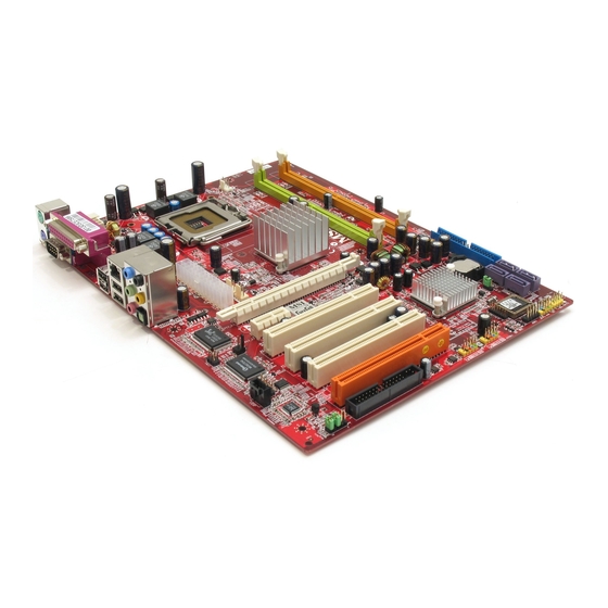
Page 14: Mainboard Layout
M S-7176 ATX Mainboard Mainboard Layout JLPC1 JPW1 Top : mouse CPUFAN1 JCI1 Winbond Bottom: keyboard W83627THG Top : Parallel Por t Bottom: COM port VGA port ports Top: LAN Jack Intel Botto m: USB ports 945G PWRFAN1 Line-In Line-Out T:RS-Out M:CS-Out B:SPD IF Out... -
Page 15: Packing Contents
Getting Started Packing Contents MSI Driver/Utility CD SATA Cable *2 MSI motherboard D-Bracket 2 Standard Cable for Power Cable (Optional) IDE Devices Standard Cable for User’s Guide Back IO Shield Floppy Disk * The pictures are for reference only and may vary... -
Page 16: Chapter 2. Hardware Setup
Chapter 2. Hardware Setup Hardware Setup This chapter tells you how to install the CPU, memory modules, and expansion cards, as well as how to setup the jumpers on the mainboard. Also, it provides the instructions on connecting the periph- eral devices, such as the mouse, keyboard, etc. -
Page 17: Quick Components Guide
M S-7176 ATX M ainboard Quick Components Guide E-2-2... -
Page 18: Central Processing Unit: Cpu
If you do not have the CPU cooler, contact your dealer to purchase and install them before turning on the computer. For the latest information about CPU, please visit http://www.msi.com.tw/ program/products/mainboard/mbd/pro_mbd_cpu_support.php. MSI Reminds You... -
Page 19: Cpu & Cooler Installation
CPU Clip to clip the CPU up, pressing the clips on both sides to the center, as the arrows shown. MSI Reminds You... 1. Confirm if your CPU cooler is firmly installed before turning on your system. - Page 20 Hardware Setup 5. The CPU has a plastic cap on it to 6. Remove the cap from lever hinge side protect the contact from damage. (as the arrow shows). The pins of Before you have installed the CPU, socket reveal. always cover it to protect the socket pin.
- Page 21 CPU. MSI Reminds You... 1. Check the information in PC Health Status of H/W M onitor in BIOS (Chapter 3) for the CPU temperature. 2. Whenever CPU is not installed, always protect your CPU socket pin with the plastic cap covered (shown in Figure 1) to avoid damaging.
-
Page 22: Memory
DDR2 memory module in the DDR2 slot (DIMM1~DIMM4). Otherwise, you are not able to boot up your system and your mainboard might be damaged. For the updated supporting memory modules, please visit http://www.msi. com.tw/program/products/mainboard/mbd/pro_mbd_trp_list.php. DIMM1~DIMM4 (from left (Green) to right(Orange)) Channel A (DIMM1 &... -
Page 23: Installing Ddr2 Modules
256MB~1GB 256MB~1GB 256MB~1GB 1GB~4GB MSI Reminds You... - Dual-channel DDR works ONLY in the 5 combinations listed in the table shown in the previous page. - Please select the identical memory modules to install on the dual channel, and DO NOT install three memory modules on three DIMMs, or it may cause some failure. -
Page 24: Power Supply
ATX2 +12V JPW1 MSI Reminds You... 1. These three connectors connect to the ATX power supply and have to work together to ensure stable operation of the mainboard. 2. Power supply of 350 watts (and above) is highly recommended for system stability. -
Page 25: Mouse/Keyboard Connector
M S-7176 ATX M ainboard Back Panel The back panel provides the following connectors: RS-Out L-In SPDIF Parallel M ou se USB Ports CS-Out COM Port VGA Port L-Out Keyboard SPDIF Mouse/Keyboard Connector The mainboard provides a standard PS/2 mouse/keyboard mini DIN connector ®... -
Page 26: Serial Port Connector: Com Port
Hardware Setup Serial Port Connector: COM Port The mainboard offers one 9-pin male DIN connector COM Port. It’s a 16550A high speed communication port that send/receive/ 16 bytes FIFOs. You can attach a serial mouse or other serial device directly to it. Pin Definition SIGNAL DESCRIPTION... -
Page 27: Lan (Rj-45) Jack
Center/Subwoofer Line Out Speaker Out (Front R/L) ( in 7.1CH / 5.1CH) M IC SPDIF-Out MSI Reminds You... For the advanced functions of the audio codec, please refer to Chapter 4: Introduction to Realtek ALC882 Audio Codec for details. E-2-12... -
Page 28: Parallel Port Connector: Lpt1
Hardware Setup Parallel Port Connector: LPT1 The mainboard provides a 25-pin female centronic connector as LPT. A parallel port is a standard printer port that supports Enhanced Parallel Port (EPP) and Ex- tended Capabilities Parallel Port (ECP) mode. Pin Definition SIGNAL DESCRIPTION STROBE... -
Page 29: Floppy Disk Drive Connector: Fdd1
P W R F A N 1 C P U F A N 1 S Y S F A N 1 MSI Reminds You... 1. Always consult the vendors for proper CPU cooling fan. 2. CPU_FAN supports the fan control. Fan/heatsink with 3 or 4 fins are both available. -
Page 30: Hard Disk Connector: Ide1, Ide2, Ide3
Each one can connect a Master and a Slave drive. You must configure second hard drive to Slave mode by setting the jumper accordingly. MSI Reminds You... If you install two hard disks on cable, you must configure the second drive to Slave mode by setting its jumper. -
Page 31: Serial Ata Connectors Controlled By Intel Ich7: Sata1~Sata4
Take out the dust cover and connect to the hard disk devices Connect to serial ATA ports MSI Reminds You... Please do not fold the serial ATA cable in a 90-degree angle, since this might cause the loss of data during the transmission. E-2-16... -
Page 32: Cd-In Connector: Jcd1
Hardware Setup CD-In Connector: JCD1 The connector is for CD-ROM audio connector. JCD1 Front Panel Connectors: JFP1 / JFP2 The mainboard provides two front panel connectors for electrical connection to the front panel switches and LEDs. JFP1 is compliant with Intel Front Panel I/O ®... -
Page 33: Front Usb Connectors: Jusb1 / Jusb2
USB1+ JUSB1 / JUSB2 (USB 2.0/standard spec) USBOC MSI Reminds You... Note that the pins of VCC and GND must be connected correctly, or it may cause some damage. Front Panel Audio Connector: JAUD1 The F_AUDIO front panel audio connector allows you to connect to the front panel audio and is compliant with Intel Front Panel I/O Connectivity Design Guide. -
Page 34: Ieee 1394 Connector: J1394_1/J1394_2 (Optional
Hardware Setup IEEE 1394 Connector: J1394_1/J1394_2 (Optional) The mainboard provides two 1394 pin headers that allow you to connect optional IEEE 1394 port. Pin Definition SIGNAL SIGNAL TPA+ TPA- Ground Ground TPB+ TPB- Cable power Cable power J1394_1 / J1394_2 Key (no pin) Ground How to attach the IEEE 1394 Port:... -
Page 35: D-Bracket™ 2 Connector: Jdb1
M S-7176 ATX M ainboard D-Bracket™ 2 Connector: JDB1 The mainboard comes with a JDB1 connector for you to connect to D-Bracket™ 2. D-Bracket™ 2 is a USB Bracket that supports both USB1.1 & 2.0 spec. It integrates four LEDs and allows users to identify system problem through 16 various combina- tions of LED signals. - Page 36 Hardware Setup Description D-Bracket™ 2 System Power ON The D-LED will hang here if the processor is damaged or not installed properly. Early Chipset Initialization Memory Detection Test Testing onboard memory size. The D-LED will hang if the memory module is damaged or not installed properly. Decompressing BIOS image to RAM for fast booting.
-
Page 37: Fwh/Lpc Debugging Pin Header: Jlpc1
M S-7176 ATX M ainboard D-Bracket™ 2 Description Testing Base and Extended Memory Testing base memory from 240K to 640K and extended memory above 1MB using various patterns. Assign Resources to all ISA. Initializing Hard Drive Controller This will initialize IDE drive and controller. Initializing Floppy Drive Controller This will initialize Floppy Drive and controller. -
Page 38: Jumpers
JBAT1 Keep Data Clear Data MSI Reminds You... You can clear CMOS by shorting 2-3 pin while the system is off. Then return to 1-2 pin position. Avoid clearing the CMOS while the system is on; it will damage the mainboard. -
Page 39: Slots
M S-7176 ATX M ainboard Slots The mainboard provides a PCI Express x16 slot, a PCI Express x1 slot and three 32-bit PCI bus slots. PCI Express Slots (optional) The PCI Express slots, as a high-bandwidth, low pin count, serial, intercon- nect technology, support Intel highest performance desktop platforms utilizing the Intel Pentium 4 processor with HT Technology. -
Page 40: Pci (Peripheral Component Interconnect) Slots
Hardware Setup PCI (Peripheral Component Interconnect) Slots The PCI slots allow you to insert the expansion cards to meet your needs. W hen adding or removing expansion cards, make sure that you unplug the power supply first. Meanwhile, read the documentation for the expansion card to make any necessary hardware or software settings for the expansion card, such as jumpers, switches or BIOS configuration. -
Page 41: Chapter 3. Bios Setup
SETUP. ² You want to change the default settings for customized features. MSI Reminds You... 1. The items under each BIOS category described in this chapter are under c ontinuous update for better s y s tem performanc e. -
Page 42: Entering Setup
The preset Optimal Defaults of the BIOS setup program provide optimal performance settings for all devices and the system. MSI Reminds You... The items under each BIOS category described in this chapter are under continuous update for better system performance. Therefore, the description may be slightly different from the latest BIOS and should be held for reference only. -
Page 43: The Main Menu
BIOS Setup The Main Menu Once you enter AwardBIOS CMOS Setup Utility, the Main Menu will appear on the screen. Use arrow keys to move among the items and press <Enter> to enter the sub-menu. Standard CMOS Features Use this menu for basic system configurations, such as time, date etc. Advanced BIOS Features Use this menu to setup the items of Award special enhanced features. - Page 44 M S-7176 ATX M ainboard Load Fail-Safe Defaults Use this menu to load the default values set by the BIOS vendor for stable system performance. Load Optimized Defaults Use this menu to load the default values set by the mainboard manufacturer specifically for optimal performance of the mainboard.
-
Page 45: Cell Menu
BIOS Setup Cell Menu The items here includes some important settings of CPU and PCI functions. MSI Reminds You... Change these settings only if you are familiar with the chipset. Current CPU/FSB/DRAM Clock This item only displays the current CPU/FSB/DRAM clock. - Page 46 M S-7176 ATX M ainboard DRAM Timing Setectable This field allows you to select the DRAM timing setting. Setting to Auto enables Max Memclock (Mhz) automatically to be determined by SPD. Selecting Manual allows users to configure these fields manually. CAS Latency Time This controls the timing delay (in clock cycles) before SDRAM starts a read command after receiving it.
- Page 47 Increasing the CPU frequency by 7%~8%. [Commander] Increasing the CPU frequency by 8%~9%. MSI Reminds You... 1. Even though the Dynamic Overclocking Technology is more stable than manual overclocking, basically, it is still risky. We suggest user to make sure that your CPU can afford to overclocking regu- larly first.
- Page 48 M S-7176 ATX M ainboard Spread Spectrum W hen the motherboard’s clock generator pulses, the extreme values (spikes) of the pulses creates EMI (Electromagnetic Interference). The Spread Spectrum function reduces the EMI generated by modulating the pulses so that the spikes of the pulses are reduced to flatter curves.
-
Page 49: Load Fail-Safe/Optimized Defaults
BIOS Setup Load Fail-Safe/Optimized Defaults The two options on the main menu allow users to restore all of the BIOS settings to the default Fail-Safe or Optimized values. The Optimized Defaults are the default values set by the mainboard manufacturer specifically for optimal performance of the mainboard. -
Page 50: Bios Setting Password
M S-7176 ATX M ainboard BIOS Setting Password W hen you select this functions, a message as below will appear on the screen: Type the password, up to six characters in length, and press <Enter>. The password typed now will replace any previously set password from CMOS memory. You will be prompted to confirm the password. -
Page 51: Français
945G Series Manuel d’utilisation Français... - Page 52 Introduction Féliciation vous venez d’acheter une carte mère ATX 945G Series (MS-7176) v1.x La 945G Series est basée sur les chipsets Intel 945G et Intel ® ® ICH7/ICH7R of frant des perf ormanc es importantes. Elle fonctionne avec les processeurs Intel Pentium 4 Prescott LGA775 et offre un système hautement ®...
-
Page 53: Spécificités
† Supportel’architecture de mémoire DDR Dual channel. † Supporte la mémoire d’interface DDR2 533/667. † (Pour une mise à jour sur les modules de mémoire, merci de visiter http://www.msi. com.tw/program/products/mainboard/mbd/pro_mbd_trp_list.php.) Slots 1 slot PCI Express 16x. † 2 slots PCI Express 1x. - Page 54 Getting Started Contrôleur SATAII intégré dans ICH7/ICH7R. † - Taux de transfert jusqu’à 300MB/sec. - Possibilité de connecter jusqu’à quatre matériaux SATAII. - Supporte les contrôleurs AHCI avec SATA Raid 0, Raid 1, Raid 5, Raid 10 et Matrix Raid (ICH7R). Chipset VIA 6410.
-
Page 55: Schéma
Carte M ère ATX MS-7176 M a inb oa rd Schéma JLPC1 JPW1 Top : mouse CPUFAN1 JCI1 Winbond Bottom: W83627THG keyboard Top : Parallel Por t Bottom: COM port ports Top: LAN Jack Intel Botto m: USB ports 945P PWRFAN1 Line-In Line-Out... - Page 56 Getting Started Connecteur d’aliemntation ATX 24 broches: ATX1 Ce connecteur permet une connection à l’alimentation ATX. Connecteur d’aliemntation: JPW1 & ATX2. Ces deux connecteurs vous procurent une connection à une alimentation 12V. Connecteur Floppy Disk Drive : FDD1. Cette carte mère procure un connecteur standard floppy disk drive supportant les types floppy disk 360K, 720K, 1.2M, 1.44M et 2.88M Connecteur d’alimentation de ventilateur: CPUFAN1, PWRFAN1, NBFAN1...
- Page 57 Carte M ère ATX MS-7176 M a inb oa rd Connecteurs Front USB: JUSB1 & JUSB2 Cette carte mère procure 3 connecteurs standards USB2.0 JUSB1, JUSB2 & JUSB3. Connecteur Front Panel Audio: JAUD1 Ce connecteur Front Panel Audio permet une connection au front panel audio. Connecteur InfraRouge IrDA : Ce connecteur permet la connection au module infrarouge IrDA.
-
Page 58: Installation Du Cpu Et Du Ventilateur
MSI Vous Rappelle... 1. Assurez-vous que le ventilateur du CPU est correctement installé avant d’allumer votre PC. 2. Ne touchez pas les broches du socket afin d’éviter de l’endommager. - Page 59 Carte M ère ATX MS-7176 M a inb oa rd 5. Le s oc ket du CPU pos sède une 6. Retirez la protection. Les broches du protection en plastique pour éviter socket sont visibles. de l’endomager. Avant d’installer le CPU, couvrez le afin de protéger les broches du socket.
- Page 60 Getting Started 12. Abaissez le levier puis sécurisez le 11. Regardez si le CPU est bien installé en l’attachant au méchanisme de sur le socket. Sinon retirez le CPU et rétention. installez le de nouveau. Refermez le plateau. 14. Apuuez sur les quatres parties puis 13.Alignez les trous de la carte mère effectuer une rotation en se référant avec le ventilateur.
-
Page 61: Mémoire
Carte M ère ATX MS-7176 M a inb oa rd Mémoire La carte mère procure 4 slots (240 broches) DDR2 DIMM, qui supporte jusqu’à 4GB de mémoire. Depuis que les modules DDR2 modules ne sont pas interchangeables avec DDR1 et que DDR2 standard n’est pas rétro compatible, vous devez installer les modules de mémoire DDR2 dans les slots DDR2 (DIMM1~DIMM4). -
Page 62: Installation Des Modules Ddr2
256MB~1GB 256MB~1GB 256MB~1GB 1GB~4GB MSI Vous Rappelle... - Le Dual-channel DDR fonc tionne uniquement av ec les cinq combinaisons précédemment citées. - Merci de séléctionner des mémoires indentiques pour installer en Dual Channel et de ne pas installer trois modules de mémoires sur trois DIMMs, afin de ne rien endommager - Toujours insérer des modules de mémoire sur les slots verts en... -
Page 63: Panneau Arričre
Carte M ère ATX MS-7176 M a inb oa rd Panneau Arrière Le panneau arrière procure les connecteurs suivants: RS-Out L-In SPDIF Parallèle Souris CS-Out Ports USB Port COM L-Out Clavier VGA Port SPDIF Setup du BIOS Allumez votre ordinateur, le système lance le processus de POST (Power On Self Test). -
Page 64: Aide
Getting Started Aide Après être entré dans l’utilitaire du Setup, le premier écran que vous voyez est le menu principal. Menu Principal Le menu principal présente les catégories intégrées au setup du BIOS. Vous pouvez utiliser les flèches ( pour séléctionner un choix. La description de la catégori choisie se trouve eu abs de l’écran. - Page 65 Carte M ère ATX MS-7176 M a inb oa rd Integrated Peripherals Utilisez ce menu pour spécifier les paramètres des périphériques intégrés. Power M anagement Setup Utilisez ce menu pou rspécifier les paramètres du “power management”. PNP/PCI Configurations Cet élément apparait si votre système supporte le PnP/PCI. H/W/ M onitor Voir les statuts des CPU, ventilateur, et alarme système.
-
Page 66: Cell Menu
Getting Started Cell Menu Les items suivants inclus d’importants paramètres du des fonctions CPU et PCI. MSI Vous Rappelle.. Ne modifiez ces paramčtres que si vous ętes familiarisés avec le chipset. Current CPU / DRAM / FSB Clock Vitesse d’horloge des CPU/FSB/DRAM. - Page 67 D.O.T.3 Step0 Setting Vous pouvez activer la fonction DOT3 en paramètrant le champ sur [Normal]. Dynamic Overclocking Technology 3 est la fonction d’overclocking automatique intégrant la nouvelle technologie développée par MSI ’s : la technologie CoreCell .Utilisé pour détecter le chargement du CPU lors du fonctionnement des programmes et pour ajuster automatiquement la meilleure fréquence de CPU.
- Page 68 Augmente la fréquence du CPU de 7%~8%. [Commander] Augmente la fréquence du CPU de 8%~9%. MSI Vous Rappelle... 1. Même lorsque le Dynamic Overclocking Technology est plus stable que l’ overclocking manuel, cela est toujours risqué. Nous vous suggérons de vous assurez tout d’abord que votre CPU supporte l’overclocking régulier.
- Page 69 Carte M ère ATX MS-7176 M a inb oa rd Spread Spectrum Les cartes mères créées des EMI (Electromagnetic Interference). La fonction Spread Spectrum réduit ces EMI. Si vous n’avez pas de problème d’EMI, laissez l’option sur [Disabled]. Dans le cas contraire, choisissez [enabled] et n’oubliez pas de désactiver cette fonction lors d’overclocking afin d’éviter tout problème.
-
Page 70: Deutsch
945G Series Benutzerhandbuch Deutsch... - Page 71 Einleitung Danke, dass Sie das 945G Series (MS-7176) V1.X ATX Mainboard gewählt haben. Das 945G Series Mainboard basiert auf dem Intel 945G und Intel ICH7/ICH7R Chipsatz und ermöglicht ® ® somit ein optimales und effizientes System. Entworfen, um den hochentwickelten Intel Pentium 4 Prescott LGA775 Prozessor ®...
-
Page 72: Spezifikationen Des Mainboards
† Unterstützt 3 und 4 Pin CPU Lüfteranschlüsse mit Geschwindigkeitskontrolle. † Unterstützt Prozessoren bis zu Pentium 4 3XX, 5XX, 6XX & P4EE (Intel Pentium 4 Prozessor mit HT Technologie Extreme Edition). (Die neuesten Informationen zu unterstützten Prozessoren finden Sie unter http:// www.msi.com.tw/program/products/mainboard/mbd/pro_mbd_cpu_support.php) Chipsatz † Intel 945G Chipsatz ®... - Page 73 Einleitung - Bis zu sechs Ultra ATA Laufwerke anschließbar. † Ein in den ICH7/ICH7R integrierter SATAII Kontroller. - Übertragungsgeschwindigkeiten von bis zu 300MB/s. - Bis zu vier SATAII Laufwerke anschließbar. - Unterstützt AHCI Kontroller mit SATA Raid 0, 1, 5, 10 und Matrix Raid (ICH7R). †...
-
Page 74: Mainboard Layout
M S-7176 ATX Mainboard Mainboard Layout JLPC1 JPW1 Oben : Maus CPUFAN1 JCI1 Winbond Unten: Tastatur W83627THG Oben : Parallel Por t Unten: COM Port Ports Oben: LAN Buchse Intel Unten: USB Ports 945P PWRFAN1 O Line-In Line-A usgang U Mikrofon O:RS-Ausgang M:CS-A usgang U:SPDIF Ausgang... - Page 75 Einleitung ATX 24-Pin Stromanschluss: ATX1 Hier können Sie ein ATX Netzteil anschließen ATX 12V Stromanschluss: JPW1 & ATX2 Diese zwei Stromanschlüsse werden verwendet, um die Versorgung mit 12V Strom zu gewährleisten. Anschluss des Diskettenlaufwerks: FDD1 Das Mainboard verfügt über einen Standardanschluss für Diskettenlaufwerke mit 360 KB, 720 KB, 1,2 MB, 1,44 MB oder 2,88 MB Kapazität.
- Page 76 M S-7176 ATX Mainboard USB Vorderanschlüsse: JUSB1, JUSB2 Das Mainboard verfügt über zwei Standard- USB- 2.0- Anschlüsse in Form der Stift- Blöcke JUSB1 & JUSB2. Audioanschluss des Frontpaneels: JAUD1 Dieser Audio Vorderanschluss ermöglicht den Anschluss eines Frontpaneels. Infrarotmodul Stifleiste: JIR1 Gestattet den Anschluss eines Infrarotmoduls.
-
Page 77: Cpu & Kühler Einbau
Seiten zur Mitte hin drücken, wie die berühren. Pfeile es anzeigen. MSI weist darauf hin... 1. Stellen Sie sicher, dass Ihr CPU Kühler fest eingebaut ist, bevor Sie Ihr System anschalten. 2. Berühren Sie die Pins des CPU Sock els nicht, um Schaden zu vermeiden. - Page 78 M S-7176 ATX Mainboard 5. Um die Kontakte vor Schäden zu 6. Entfernen Sie die Kappe von der Seite des Hebelgelenks her (W ie der Pfeil schützen, ist der CPU-Sockel auf zeigt). Die Pins des Sockels werden der Oberseite mit einer Plastikkappe frei gelegt.
- Page 79 Sie den Clip auf, um die CPU herauszuheben. MSI weist darauf hin... 1. Überprüfen Sie die Temperatur der CPU im “ PC Health Status” im BIOS (Kapitel 3). 2. Schützen Sie die Pins des CPU Sockels stets vor Schaden (wie gezeigt in Schritt 5), indem Sie sie mit der Plastikkappe abdecken, immer wenn keine CPU installiert ist.
-
Page 80: Speicher
M S-7176 ATX Mainboard Speicher Das Mainboard bietet 4 Sockel für 240-pin DDR2 DIMMs, und unterstützt den Speicherausbau auf bis zu 4GB. Da DDR2 und DDR1 Module nicht untereinander austauschbar sind und der DDR2 Standard nicht rückwärtskompatibel ist, sollte stets ein DDR2 Speichermodul in den DDR2 Sockel eingesetzt werden(DIMM1~DIMM4). -
Page 81: Einbau Von Ddr2 Modulen
Sie ihn hinein, bis die goldenen Kontakte tief im Sockel sitzen. 3. Die Plastikklammern an den Seiten des DIMM- Sockels schließen sich automatisch. Kerbe Volt MSI weist darauf hin... Die goldenen Kontakte sind kaum noch sichtbar, wenn die Module richtig eingesetzt sind. G-13... -
Page 82: Hinteres Anschlusspaneel
M S-7176 ATX Mainboard Hinteres Anschlusspaneel Das hintere Anschlusspaneel verfügt über die folgenden Anschlüsse: RS-Out L-In SPDIF Parallel M aus Ausgang CS-Out USB Ports COM Port VGA Port Tastatur SPDIF M ikro Aufruf des BIOS Setup Nach dem Einschalten beginnt der Computer den POST (Power On Self Test - Selbstüberprüfung nach Anschalten). -
Page 83: Default Settings
Werkseinstellungen. Die Voreinstellung “Optimal Defaults” des BIOS stellt die besten Leistungseinstellungen für all Komponenten und das System zur Verfügung. MSI weist darauf hin... Die Menüpunkte jeder in diesem Kapitel beschriebenen BIOS Kategorie befinden sich in permanenter Weiterentwicklung um die Systemleistung zu verbessern. - Page 84 M S-7176 ATX Mainboard Integrated Peripherals Verwenden Sie dieses Menü, um die Einstellungen für in das Board integrierte Peripheriegeräte vorzunehmen. Power M anagement Setup Verwenden Sie dieses Menü, um die Einstellungen für die Stromsparfunktionen vorzunehmen. PNP/PCI Configurations Dieser Eintrag erscheint, wenn Ihr System Plug and Play- Geräte am PCI-Bus unterstützt.
-
Page 85: Cell Menu
Einleitung Cell Menu Hier können Sie einige wichtige Einstellungen zu CPU und PCI Funktionen vornehmen. MSI weist darauf hin... Ändern Sie diese Einstellungen nur, wenn Sie mit diesem Chipsatz vertraut sind. Current CPU/FSB/DRAM Clock Gibt nur den derzeitigen Takt von CPU/FSB und DRAM wieder. - Page 86 D.O.T.3 Step0 Setting Sie können die DOT3 Funkton aktivieren, indem Sie diesen Menüpunkt auf [Normal] setzen. Dynamic Overclocking Technology 3 ist die automatische Übertaktungsfunktion, die in MSI ’s neu entwickelter CoreCell Technologie enthalten ist. Sie dient zur Feststellung des Auslastungsgrades der CPU, während diese Programme abarbeitet, und passt die CPU-Frequenz automatisch an.
- Page 87 Steigerung der CPU Frequenz um 7%~8%. [Commander] Steigerung der CPU Frequenz um 8%~9%. MSI weist darauf hin... 1. O bgleic h Dy namic O verc lock ing Tec hnology stabiler is t als manuelles Übertakten, ist es dennoch grundsätzlich riskant. Es ist empfehlenswert zuerst sicher zu stellen, dass Ihre CPU eine regelmäßige Übertaktung verträgt.
- Page 88 M S-7176 ATX Mainboard Spread Spectrum Pulsiert der Taktgenerator des Motherboards, erzeugen die Extremwerte (Spitzen) der Pulse Elektromagnetische Interferenzen (sog. EMI). Die Spread Spectrum Funktion reduziert die erzeugten EMI, indem die Pulse so moduliert werden, das die Pulsspitzen zu flacheren Kurven reduziert werden. Sollten Sie keine Probleme mit Interferenzen haben, belassen Sie es bei der Einstellung [Disabled] (ausgeschaltet), um bestmögliche Systemstabilität und -leistung zu gewährleisten.