
Related Manuals for MSI K8N SLI-F


Summary of Contents for MSI K8N SLI-F
- Page 1 K8N SLI Series MS-7185 (v1.X) ATX Mainboard English/ German/ French Version G52-M7185X3...
-
Page 2: Copyright Notice
If a problem arises with your system and no solution can be obtained from the user’s manual, please contact your place of purchase or local distributor. Alternatively, please try the following help resources for further guidance. Visit the MSI website for FAQ, technical guide, BIOS updates, driver updates, and other information: http://www.msi.com.tw/program/service/faq/ faq/esc_faq_list.php... -
Page 3: Safety Instructions
Safety Instructions Always read the safety instructions carefully. Keep this User’s Manual for future reference. Keep this equipment away from humidity. Lay this equipment on a reliable flat surface before setting it up. The openings on the enclosure are for air convection hence protects the equip- ment from overheating. - Page 4 FCC-B Radio Frequency Interference Statement T h is eq uip men t h as been tested and found to c omply with the limits for a Class B digital device, pursuant to Part 15 of the FCC Rules. These limits are designed to provide reasonable protection against harmful interference in a residential installation.
- Page 5 WEEE (Waste Electrical and Electronic Equipment) Statement...
- Page 8 CONTENTS Copyright Notice ....................... ii Trademarks ........................ii Revision History ....................... ii Technical Support ......................ii Safety Instructions ......................iii FCC-B Radio Frequency Interference Statement ............iv W EEE (Waste Electrical and Electronic Equipment) Statement ........v English ........................E-1 Deutsch ........................
- Page 9 Quick User’s Guide K8N SLI Series (MS-7185 v1.X) ATX Mainboard English...
- Page 10 MS-7185 ATX Mainboard...
- Page 11 DDR DIMMs (at 200, 266, 333, and 400 MHz) to provide the maximum of 4GB memory capacity. MSI Reminds You... 1. Please note that the companion MSI Driver/Utility CD supports this mainboard with Windows 2000/XP system drivers ONLY. 2. To create a bootable RAID volume for a Windows 2000 environment, Microsoft’s Windows 2000 Service Pack 4...
-
Page 12: Mainboard Specifications
Slots † Three 32-bit/33MHz Master PCI Bus slots, including one orange slot which sup- ports 2 master for MSI special PCI function card (ex. wireless LAN and bluetooth combo card) † Two PCI Express x1 slots (PCI Express Bus specification v1.0a compliant) †... - Page 13 Quick User’s Guide NV RAID (Software) † Supports up to 4 SATA and 4 PATA133 Hard drives - RAID 0 or 1, 0+1, JBOD supported - RAID function available for PATA133+SATA H/D or 4 SATA H/D drives Onboard Peripherals † 1 floppy port supports 1 FDD with 360KB, 720KB, 1.2MB, 1.44MB, and 2.88MB †...
-
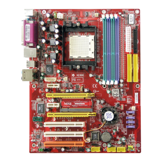
Page 14: Quick Components Guide
MS-7185 ATX Mainboard Quick Components Guide PCIE_PW1, JPW1, p. E-12 CPUFAN1, SFAN1, p. E-12 DDR DIMMs, p. E-10 JCI1, p. E-15 I/O Ports, p. E-14 ATX1, p. E-12 JIR1, p. E-17 FDD1, p. E-15 IDE1/2, p. E-16 NBFAN1, p. E-16 PCI Express Slots, p. -
Page 15: Cpu Installation Procedures For Socket 939
Quick User’s Guide Central Processing Unit: CPU CPU Installation Procedures for Socket 939 1. Please turn off the power and unplug the power cord before installing the CPU. Open Lever Sliding 90 degree Plate 2. Pull the lever s ideways away from the socket. -
Page 16: Installing Amd Athlon64 Cpu Cooler Set
MSI Reminds You... Mainboard photos shown in this section are for demonstration of the cooler installation for Socket 939 CPUs only. The appearance of your mainboard may vary depending on the model you purchase. - Page 17 Safety Hook Fixed Lever Fixed Bolt MSI Reminds You... While disconnecting the Safety Hook from the fixed bolt, it is neces- sary to keep an eye on your fingers, because once the Safety Hook is disconnected from the fixed bolt, the fixed lever will spring back...
-
Page 18: Dimm Module Combination
The mainboard provides 4 slots for 184-pin DDR DIMM (Double In-Line Memory Module) modules and supports the memory size up to 4GB. You can install DDR 266/333/400 modules on the DDR DIMM slots (DIMM 1~4). For the updated supporting memory modules, please visit http://www.msi.com.tw/ program/products/mainboard/mbd/pro_mbd_trp_list.php. DIM M1~DIMM4... -
Page 19: Recommended Memory Combination List
Quick User’s Guide Recommended Memory Combination List DIMM Slots Green Green Purple Max Speed Purple DIMM1 DIMM2 DIMM3 DIMM4 DDR 400 DDR 400 DDR 400 DDR 400 DDR 400 DDR 333 DDR 400 DDR 400 DDR 400 DDR 400 DDR 333 S: Single Side D: Double Side Installing DDR Modules... -
Page 20: Power Supply
SIGNAL JPW1 LED1 +12V MSI Reminds You... 1. Maker sure that all three connectors are connected to adequate ATX power supplies to ensure stable operation of the mainboard. 2. Power supply of 450watts (and above) is highly recommended for system stability. -
Page 21: Important Notification About Power Issue
1st installation or during system upgrade procedure. Unplug the AC power cable Unplug the power connector Unplug power connectors MSI Reminds You... Mainboard photos shown in this section are for demonstration only. The appearance of your mainboard may vary depending on the model you purchased. -
Page 22: Back Panel
MS-7185 ATX Mainboard Back Panel L-In RS-Out Parallel M ou se L-Out CS-Out Keyboard Serial Port 1394 Port SPDIF USB Ports SPDIF Out (Optical) (Coaxial) M ouse/Keyboard Connector RJ-45 LAN Jack Pin5 Mouse/KBD Clock Pin6 NC Pin4 VCC Pin3 GND Gigabit LAN Pin1 Pin2 NC... - Page 23 Serial ATA cable Take out the dust cover and connect to the hard disk devices Connect to SATA1/2/3/4 MSI Reminds You... Please do not fold the Serial ATA cable into 90-degree angle. Otherwise, data loss may occur during transmission. E-15...
- Page 24 SENSOR CPUFAN1 SFAN1 SFAN2 NBFAN1 MSI Reminds You... 1. CPUFAN1 supports fan control. You can install Core Center utility that will automatically control the CPU fan speed according to the actual CPU temperature. ® 2. Please refer to the recommended CPU fans at AMD official website.
- Page 25 HP_ON AUD_MIC_BIAS AUD_FPOUT_R MSI Reminds You... If you don’t want to connect to the front audio header, pins 5 & 6, 9 & 10 have to be jumpered in order to have signal output directed to the rear audio ports. Otherwise, the Line-Out connector on the back panel will not function.
- Page 26 MS-7185 ATX Mainboard D-Bracket™ 2 Connector: JDB1 JDB1 The mainboard comes with a JDB1 connector for you to connect to D-Bracket™ 2. D-Bracket™ 2 is an external DBR3 DBR4 DBR2 USB Bracket that supports both USB1.1 & 2.0 spec. It DBR1 integrates four LEDs and allows users to identify sys- DBG1...
- Page 27 Connect to JUSB1, JUSB2, or JUSB3 (the USB pinheader in YELLOW color) USB 2.0 Bracket (Optional) MSI Reminds You... Note that the pins of VCC and GND must be connected correctly to avoid possible damage. Button Clear CMOS Button: SW1 CMOS stands for Complementary Metal-Oxide Semiconductor and is more specifi- cally referred to as CMOS RAM.
- Page 28 MS-7185 ATX Mainboard Slots The motherboard provides two PCI Express x1 slots, two PCI Express x16 slots, and three 32-bit PCI slots. PCI (Peripheral Component Interconnect) Express Slots The PCI Express slots support high-bandwidth, low pin count, and serial interconnect technology.
-
Page 29: Pci Interrupt Request Routing
1. Push the retaining clips (on the sides of the SLI slot) outwards to release the SLI switch card. MSI Reminds You... Make sure that you unplug the power supply before removing the SLI switch card. E-21... - Page 30 PCI Express card. SLI bridge card MSI Reminds You... 1. Mainboard photos shown in this section are for demonstration only. The appearance of your mainboard may vary depending on the model you purchase.
- Page 31 6. Restart your system and a pop-up will show in the system tray confirming that M ulti-GPU has been enabled. MSI Reminds You... 1. If you want to remove one graphics card and quit the SLI function, make sure that you reset the SLI switch card (SLI mode to non-SLI mode) and disable the "MultiGPU"...
-
Page 32: Bios Setup
Load Optimized defaults <F10> Save all the CMOS changes and exit MSI Reminds You... The items under each BIOS category described in this section are under continuous update for better system performance. Therefore, the description may be slightly different from the latest BIOS and should be held for reference only. -
Page 33: The Main Menu
Quick User’s Guide The Main Menu Standard CMOS Features Use this menu for basic system configurations, such as time, date etc. Advanced BIOS Features ® Use this menu to setup the items of AWARD special enhanced features. Advanced Chipset Features Use this menu to change the values in the chipset registers and optimize your system’s performance. -
Page 34: Cell Menu
Dynamic Overclocking Dynamic Overclocking Technology is the automatic overclocking function, included in ’s newly developed CoreCell the MSI Technology. It is designed to detect the load balance of CPU while running programs, and to adjust the best CPU frequency automatically. W hen the motherboard detects CPU is running programs, it will speed up CPU automatically to make the program run smoothly and faster. - Page 35 5th level of overclocking, increasing the CPU frequency by 9%. [Commander] 6th level of overclocking, increasing the CPU frequency by 11%. MSI Reminds You... Even though the Dynamic Overclocking Technology is more stable than manual overclocking, basically, it is still risky. Users are sug- gested to check their CPU’s overclocking capability first.
- Page 36 CPU’s from overheating due to the heavy working loading. Setting options: [Disabled], [Auto]. MSI Reminds You... For the purpose of ensuring the stability of Cool'n'Quiet function, it is always recommended to have the memories plugged in DIMM1.
- Page 37 Kurzanleitung K8N SLI Series (MS-7185 V1.X) ATX Mainboard Deutsch...
- Page 38 MS-7185 ATX Mainboard...
- Page 39 144-bit DDR DIMMs (mit 200, 266, 333 und 400 MHz) - womit es einen maximalen Speicherausbau auf bis zu 4GB ermöglicht. MSI weist darauf hin... 1. Beachten Sie bitte, dass die beigelegte MSI Treiber/Utility CD AUSCHLIESSLICH dieses Mainboard mit Windows 2000/XP Systemtreibern unterstützt.
- Page 40 Steckplätze † Drei 32-bit/33Mhz Master PCI Bus Slots, einschließlich eines orangefarbenen, der 2 Master für MSI PCI Karten mit Spezialfunktion bereit stellt (z.B. W ireless LAN und Bluetooth Kombikarte) † Zwei PCI Express x1 Slots (erfüllen die PCI Express Bus Spezifikation V1.0a) †...
- Page 41 Kurzanleitung NV RAID (Software) † Unterstützt bis zu 4 SATA und 4 PATA133 Festplatten - Bietet RAID 0 oder 1, 0+1, sowie JBOD ( Betrieb ohne Raid- Funktionalität) - RAID Funktionalität verfügbar für PATA133+SATA Festplatten oder 4 SATA Festplatten Peripherieanschlüsse onboard †...
- Page 42 MS-7185 ATX Mainboard Kurzeinführung Komponenten PCIE_PW1, JPW1, S. D-12 CPUFAN1, SFAN1, S. D-12 DDR DIMMs, S. D-10 JCI1, S. D-15 Ein-/Ausgabe Ports, S. D-14 ATX1, S. D-12 JIR1, S. D-17 FDD1, S. D-15 IDE1/2, S. D-16 NBFAN1, S. D-16 PCI Express Slots, S.
- Page 43 Kurzanleitung Hauptprozessor: CPU CPU Einbau Sockel 939 1. Bitte Schalten Sie das System aus und ziehen Sie den Netz-stecker, bevor Sie die CPU einbauen. Hebel 鐪fnen Hebel öffnen Gleitplatte 90 Grad 2. Ziehen Sie den Hebel leicht seitlich weg vom Soc kel, heben Sie ihn danach bis zu einem Winkel von ca.
- Page 44 Sie sich bitte mit Ihrem Händler in Verbindung, um einen solchen zu erwerben und zu installieren, bevor Sie Ihren Computer anschalten. MSI weist darauf hin... Die Mainboarddarstellungen in diesem Abschnitt dienen lediglich zur Demonstration des Kühlereinbaus bei CPUs für den Sockel 939. Die Erscheinung Ihres Mainboards kann in Abhängigkeit vom erworbenen...
- Page 45 9. Verbinden Sie das Stromkabel des CPU Lüfters mit dem Anschluss auf dem Mainboard. Sicherungs- haken Fixed Bolt Sicherungshebel Sicherungsbolzen MSI weist darauf hin... Es besteht Verletzungsgefahr, wenn Sie den Sicherungshaken vom Sicherungsbolzen trennen. Sobald der Sicherungshaken gelöst wird, schnellt der Sicherungshaken sofort zurück.
- Page 46 Module) und unterstützt den Speicherausbau auf bis zu 4GB. Sie können DDR266/ 333 oder 400 Module in die DDR DIMM Sockel einsetzen (DIMM 1- 4). Um den letzten Stand bezüglich der unterstützten Speichermodule zu erhalten, bes uchen Sie bitte http://www.msi.com.tw/program/produc ts/mainboard/mbd/ pro_mbd_trp_list.php . DIM M1~DIMM4...
- Page 47 Kurzanleitung List empfohlener Speicherzusammensetzungen DIMM Sockel Max. Grün Grün Geschwin- Lila Lila digkeit DIMM1 DIMM2 DIMM3 DIMM4 DDR 400 DDR 400 DDR 400 DDR 400 DDR 400 DDR 333 DDR 400 DDR 400 DDR 400 DDR 400 DDR 333 E: Einseitig D: Doppelseitig Vorgehensweise beim Einbau von DDR Modulen DDR DIMMs haben nur eine Kerbe in der Mitte des Moduls.
- Page 48 SIGNAL JPW1 LED1 +12V MSI weist darauf hin... 1. Stellen Sie die Verbindung aller drei Ans chlüs s e mit einem angemessenem ATX Netzteil sicher, um den stabilen Betrieb des Mainboards sicher zu stellen. 2. Netzteile mit 450 Watt (und mehr) werden aus Gründen der Systemstabilität dringend empfohlen.
- Page 49 Stromstecker (wie unten dargestellt). Ziehen Sie den Netzstecker Lösen Sie die Stromanschlüsse Lösen Sie die Stromanschlüsse MSI weist darauf hin... Die Mainboarddarstellungen in diesem Abschnitt dienen lediglich Demonstrationszwecken. Die Erscheinung Ihres Mainboards kann in Abhängigkeit vom erworbenen Modell abweichen. D-13...
-
Page 50: Hinteres Anschlusspaneel
MS-7185 ATX Mainboard Hinteres Anschlusspaneel L-In RS-Out Parallel M aus L-Out CS-Out Serieller 1394 Port SPDIF Tastatur USB Ports SPDIF Out Port (Optical) (Koaxial) Maus-/Tastaturanschluss RJ-45 LAN Buchse Connector Pin5 Mouse/KBD Clock Pin6 NC Pin4 VCC Pin3 GND Gigabit LAN Pin1 Pin2 NC Mouse/KBD... - Page 51 Sie die Verbindung mit den Festplatten her Verbindung zu SATA1/2/3/4 MSI weist darauf hin... Bitte falten Sie das Serial ATA Kabel nicht in einem Winkel von 90 Grad, da dies zu Datenverlusten während der Datenübertragung führt. D-15...
- Page 52 SFAN1 SFAN2 NBFAN1 MSI weist darauf hin... 1. CPUFAN1 unterstützt Lüfterkontrolle. Sie können das Utility Core Cent er in s tallier en, das s d en C PU L üft er a uto matis c h in Abhängigkeit von der tatsächlichen CPU Temperatur steuert.
- Page 53 AUD_MIC HP_ON AUD_MIC_BIAS AUD_FPOUT_R MSI weist darauf hin... Wenn Sie die vorderen Audioanschlüsse nicht verwenden, müssen die Pins 5 & 6 und 9 & 10 mit sog. „Jumpern” gebrückt werden, um die Signalausgabe auf die hinteren Audioanschlüsse umzuleiten. Andernfalls ist der Line - Out Ausgang im hinteren Anschlussfeld ohne Funktion.
- Page 54 MS-7185 ATX Mainboard D-Bracket™ 2 Anschluss: JDB1 Das Mainboard verfügt über einen JDB1 Anschluss, der JDB1 den Anschluss der D-Bracket™ 2 ermöglicht. Die D- DBR3 DBR4 DBR2 Bracket™ 2 ist ein USB Slotblech, das die Spezifikationen DBR1 USB1.1 und 2.0 befolgt. Es beinhaltet vier LEDs und DBG1 ermöglicht es dem Anwender Probleme zu identifizieren, DBG4...
- Page 55 Verbindung zu JUSB1, JUSB2, oder JUSB3 (die USB Sifleiste in GELB) USB 2.0 Slotblech (Optional) MSI weist darauf hin... Bitte beachten Sie, dass Sie die mit VCC (Stromführende Leitung) und GND (Erdleitung) bezeichneten Pins korrekt verbinden müssen, ansonsten kann es zu Schäden kommen.
- Page 56 MS-7185 ATX Mainboard Sockel Das Mainboard stellt zwei PCI Express x1, zwei PCI Express x16 und drei 32-bit Master PCI- Bus Sockel zur Verfügung. PCI (Peripheral Component Interconnect) Express Sockel Die PCI Express Slots verwenden eine serielle Anschlusstechnologie, die sich durch eine hohe Bandbreite und eine niedrige Anzahl an Pins auszeichnet.
- Page 57 1. Drückem Sie die Rückhalteklammern (an den Seiten des SLI Sockels) nach außen, um die SLI Schaltkarte frei zu geben. MSI weist darauf hin... Stellen Sie sicher, dass Sie die Verbindung zum Netzteil trennen, bevor Sie die SLI Schaltkarte entnehmen.
- Page 58 Deswegen brauchen Sie auch nur den Monitor an die erste PCI Express Karte anzuschließen. SLI Bridge MSI weist darauf hin... 1. Die Mainboarddarstellungen in diesem Abschnitt dienen lediglich Demonstrationszwecken. Die Erscheinung Ihres Mainboards kann in Abhängigkeit vom erworbenen Modell abweichen.
- Page 59 6. Schließlich müssen Sie das System neu starten und Sie erhalten eine Information, “Multi-GPU has been enabled“, die besagt das Multi GPU nun eingeschaltet ist. MSI weist darauf hin... 1. Wollen Sie eine Grafikkarte entfernen und vom SLI-Modus zum Normalbetrieb zurückkehren, stellen Sie sicher, dass Sie die SLI Schalterkarte zurücksetzen (vom SLI Betrieb zum nicht-SLI Betrieb)
- Page 60 Lädt die optimierten W erkseinstellungen. Speichern aller Änderungen im CMOS u.Verlassen d. BIOS <F10> MSI weist darauf hin... Die M enüpunk te jeder BIO S Kategorie, die in dies em Kapitel beschrieben wird, werden permanent auf den neuesten Stand gebracht, um die Systemleistung zu verbessern. Aus diesem Grunde kann die Beschreibung geringfügig von der aktuellsten Version des...
- Page 61 Kurzanleitung Das Hauptmenü Standard CMOS Features In diesem Menü können Sie die Basiskonfiguration Ihres Systems anpassen, so z.B. die Uhrzeit, das Datum usw. Advanced BIOS Features ® Verwenden Sie diesen Menüpunkt, AWARD - spezifische weitergehende Einstellungen an Ihrem System vorzunehmen. Advanced Chipset Features Verwenden Sie dieses Menü, um die Werte in den Chipsatzregistern zu ändern und die Leistungsfähigkeit Ihres Systems zu optimieren.
- Page 62 Dynamic Overclocking Dynamic Overclocking Technology (D.O.T) ist die automatische Übertaktungsfunktion, ’s neu entwickelter CoreCell die in MSI Technologie enthalten ist. Sie dient zur Feststellung des Auslastungsgrades der CPU, während diese Programme abarbeitet, und passt die CPU-Frequenz automatisch an. Stellt das Motherboard fest, dass die CPU Programme ausführt, beschleunigt es automatisch die CPU und erlaubt so eine...
- Page 63 [General] [Commander] Sechste Übertaktungsstufe, Steigerung der CPU Frequenz um 11%. MSI weist darauf hin... Obgleic h die Dynamic Overc loc king Tec hnology s tabiler is t als manuelles Übertakten, ist es dennoch grundsätzlich riskant. Es ist empfehlens wert z uerst sic her z u stellen, das s Ihre CPU eine regelmäßige Übertaktung verträgt.
- Page 64 Erfassung der CPU Temperatur bereit, um Ihre CPU vor Überhitzung durch hohe Last zu bewahren. Mögliche Einstellungen: [Disabled] (ausgeschaltet), [Auto]. MSI weist darauf hin... Um einen stabilen Betrieb der Cool'n'Quiet Funktion sicher zu stellen, ist es immer ratsam, die Speicherbank DMM1 zu bestücken.
- Page 65 Guide d’utilisation K8N SLI Series (MS-7185 v1.X) Cart Mère ATX Français...
- Page 66 Carte Mère ATX MS-7185...
- Page 67 DDR DIMMs 144 bits (à 200, 266, 333, et 400 MHz) une capacité de mémoire maximum de 4GB. MSI Vous Rappelle... 1. Merci de noter que le CD MSI Driver/Utility de cette carte mère est uniquement compatible avec Windows 2000/XP uniquement.
- Page 68 Slots † Trois slots PCI Bus Master 32-bit/33MHz, incluant un slot orange qui supporte 2 master pour carte PCI MSI (ex. wireless LAN et carte bluetooth combo) † Deux slots PCI Express x1 (compatible avec les spécificités PCI Express Bus v1.0a)
- Page 69 Guide d’utilisation NV RAID (Software) † Supporte jusqu’à 4 ports SATA et 4 disques durs PATA133 - RAID 0 ou 1, 0+1, JBOD supporté - Fonction RAID disponible pour disques PATA133+SATA H/D ou 4 SATA H/D Périphériques Intégrés † 1 port floppy supportant 1 FDD avec 360KB, 720KB, 1.2MB, 1.44MB, et 2.88MB †...
- Page 70 Carte Mère ATX MS-7185 Guide des Composants PCIE_PW1, JPW1, p. F-12 CPUFAN1, SFAN1, p. F-12 DDR DIMMs, p. F-10 JCI1, p. F-15 I/O Ports, p. F-14 ATX1, p. F-12 JIR1, p. F-17 FDD1, p. F-15 IDE1/2, p. F-16 NBFAN1, p. F-16 PCI Express Slots, p.
- Page 71 Guide d’utilisation Central Processing Unit: CPU Procédure d’installation de CPU pour Socket 939 1. Veuillez éteindre et débrancher votr e PC avant l’installation du Open Lever Sliding 90 degree Plate 2. T ir ez le l evier vers le h aut. Assurez-vous que celui-ci est bien en position ouverte maxi- mum (angle de 90°)
- Page 72 Si vous ne possédez pas de système de refroidissement, contactez votre revendeur et installez le avant de démarrer votre PC. MSI Vous Rappelle... Les photos des cartes mères sont publiées à titre de démonstration pour l’installation du CPU Socket 939 uniquement. L’apparence de votre carte mère peut varier selon les modèles.
- Page 73 Levier de Vis de fixation fixation MSI Vous Rapelle... Lorsque vous déconnectez le crochet, il est nécessaire de garder un oeil sur vos doigts car une fois le crochet déconnecté, celui- ci reprend sa position initial du à son ressort.
- Page 74 Memory Module) et supporte une taille de mémoire jusqu’ 4GB. Vous pouvez installer des modules DDR 266/333/400 sur les slots DDR DIMM (DIMM 1~4). Pour les mises à jour des modules de mémoire, merci de visiter http://www.msi.com. tw/program/products/mainboard/mbd/pro_mbd_trp_list.php. DIM M1~DIMM4 (de gauche à...
- Page 75 Guide d’utilisation Liste des combinaisons de mémoire recommandées Slots DIMM Vert Vert Violet Vitesse Violet Maximum DIMM1 DIMM2 DIMM3 DIMM4 DDR 400 DDR 400 DDR 400 DDR 400 DDR 400 DDR 333 DDR 400 DDR 400 DDR 400 DDR 400 DDR 333 S: Single Side D: Double Side...
- Page 76 SIGNAL SIGNAL JPW1 LED1 +12V MSI Vous Rappelle... 1. Assurez-vous que les trois connecteurs sont connectés à une alimentation ATX adéquate pour assurer la stabilité des opérations de la carte mère. 2. Une alimentation de 450watts (ou plus) est fortement recommandé...
- Page 77 à jour de votre matériel comme suivant : Débrancher la prise du secteur Débrancher l’alimentation Débrancher les alimentations MSI Vous Rappelle... Les images c i-dess ous s ervent de démonstration uniquement. L’apparence de votre carte mère peut varier selon les modèles. F-13...
- Page 78 Carte Mère ATX MS-7185 Panneau Arričre L-In RS-Out Parallèle Souris L-Out CS-Out Port de Port 1394 SPDIF Clavier Ports USB SPDIF Out Série (Optical) (Coaxial) Connecteur Souris/Clavier RJ-45 LAN Jack Pin5 Mouse/KBD Clock Pin6 NC Pin4 VCC Pin3 GND Gigabit LAN Pin1 Pin2 NC Mouse/KBD...
- Page 79 Serial ATA II. Cable Serial ATA Retirez la protection et connecter le disque dur Connection à SATA1/2/3/4 MSI Vous Rappelle... Ne pas tordre les câble serial ata à un angle de 90° cela pourraît gêner la transmission des données. F-15...
- Page 80 CPUFAN1 SFAN1 SFAN2 NBFAN1 MSI Vous Rappelle... 1. CPUFAN1 supporte le contrôle de ventilateur. Vous pouvez installer l’utilitaire Core Center qui contrôlera automatiquement la vitesse du ventilateur de CPU en fonction de la température du CPU. 2. Merci de vous référer aux ventilateurs de CPU recommendés sur le ®...
- Page 81 HP_ON AUD_MIC_BIAS AUD_FPOUT_R MSI Vous Rappelle... Si vous ne voulez pas connecter le connecteur front audio , les broches 5 & 6, 9 & 10 doivent être recouvertes avec un cavalier pour que le signal de sortie soit redirigé sur les ports audio de l’arrière.
- Page 82 Carte Mère ATX MS-7185 Connecteur D-Bracket™ 2 : JDB1 JDB1 La carte mère possède un connecteur JDB1 pour con- necter un D-Bracket™ 2. D-Bracket™ 2 est un bracket DBR3 DBR4 DBR2 USB externe supportant les spécificités USB1.1 & 2.0. Il DBR1 intègre quatre LEDs et permet à...
- Page 83 USB0+ Connect to JUSB1, JUSB2, or JUSB3 (the USB pinheader in YELLOW color) USB 2.0 Bracket (Optionnel) MSI Vous Rappelle... Noter que les broches VCC et GND doivent être connecté correctement pour éviter de l’endommager. Cavaliers Cavalier Clear CMOS: SW1 CMOS (Complementary Metal-Oxide Semiconductor) se référant à...
- Page 84 Carte Mère ATX MS-7185 Slots La carte mère procure deux slots PCI Express x1, deux slots PCI Express x16, trois slots PCI 32-bit. Slots PCI (Peripheral Component Interconnect) Express Les slots PCI Express possèdent une large bande passante, supportent les plateformes desktop AMD haute performances utilisant le processeur AMD ainsi que les avantages de cette plateforme.
- Page 85 1. Tirez les clips vers l’extérieur (sur les cotés du slot SLI) pour retirer la carte SLI switch MSI Vous Rappelle... Assurez-vous que que le PC est éteint avant de retirer la carte SLI switch.
- Page 86 Par conséquent, votre écran doit être connecter sur la première carte graphique. Pont SLI MSI Vous Rappelle... 1. Les photos de la carte mère servent uniquement de démonstration et sont utilisées à titre indicatif. L’apparence de votre carte mère peut varier selon le modèle possédé.
- Page 87 6. Redémarrez votre système et un pop-up aparaîtra à l’écran, vous confirmant que le mode M ulti-GPU fonctionne bien. MSI Vous Rappelle... 1. Si vous souhaitez retirer une carte graphique et désactivez la fonction SLI, assurez-vous que le switch SLI est en mode non-SLI et que la fontionn Multi-GPU est désactivée.
-
Page 88: Setup Du Bios
Load Optimized defaults <F10> Save all the CMOS changes and exit MSI Vous Rappelle... Les descriptions des catégories de BIOS sont soumises à des mises à jour continuelles pour une meilleure performance du système Par conséquent la description peut êt elégéèrement différente du dernier BIOS et doit être utilisée à... -
Page 89: Menu Principal
Guide d’utilisation Menu Principal Standard CMOS Features Cette fonction permet le paramétrage des éléments standards du BIOS. Advanced BIOS Features Cette fonction permet de paramétrer des éléments avancés du Bios. Advanced Chipset Features Cette option vous permet de paramétrer les éléments relatifs au registre du chipset, permettant ainsi d’optimiser les performances de votre système. - Page 90 Le DOT (Dynamic Overclocking Technology) est une fonction overclocking automatique . Déstiné à détecter inclut dans la nouvelle technologie CoreCell développée par MSI la charge de travail du CPU lors de l’utilisation de programmes, le DOT permet d’augmenter la fréquence du CPU automatiquement afin que le programme soit utilisé...
- Page 91 5ème niveau d’overclocking, augmentant la fréquence CPU de [Commander] 6ème niveau d’overclocking, augmentant la fréquence CPU de MSI Vous Rappelle... Même lorsque le Dynamic Overclocking Technology est plus stable que l’ overclocking manuel, cela est toujours risqué. Nous vous suggérons de vous assurez tout d’abord que votre CPU supporte l’overclocking régulier.
- Page 92 CPU permettant ainsi d’éviter la surchauffe. Les options: [Disabled], [Auto]. MSI Vous Rappelle... Afin d’assurer la stabilité de la fonction Cool'n'Quiet, il est recommandé de mettre de la mémoire sur le DIMM1.