
Related Manuals for MSI 915GLM4-F


Summary of Contents for MSI 915GLM4-F
- Page 1 915PM4/915GM4/915GVM4/ 915GLM4/915PLM4 MS-7133 (v1.1) M-ATX Mainboard G52-M7133X4...
- Page 2 Manual Rev: 1.1 Release Date: May 2005 FCC-B Radio Frequency Interference Statement This equipment has been tested and found to comply with the limits for a class B digital device, pursuant to part 15 of the FCC rules. These limits are designed to provide reasonable protection against harmful interferenc e when the equipment is operated in a commercial environment.
-
Page 3: Copyright Notice
Copyright Notice The material in this document is the intellectual property of M ICRO-STAR INTERNATIONAL. We take every care in the preparation of this document, but no guarantee is given as to the correctness of its contents. Our products are under continual improvement and we reserve the right to make changes with- out notice. -
Page 4: Technical Support
Alternatively, please try the following help resources for further guidance. † Visit the MSI homepage & FAQ site for technical guide, BIOS updates, driver updates, and other information: http://www.msi.com.tw & http://www. -
Page 5: Table Of Contents
Chapter 1. Getting Started...1-1 Mainboard Specifications...1-2 Mainboard Layout...1-4 Packing Contents...1-5 Chapter 2. Hardware Setup...2-1 Quick Components Guide...2-2 Central Processing Unit: CPU...2-3 Introduction of LGA 775 CPU...2-3 CPU, Heatsink & Fan Installation...2-4 Memory...2-7 Introduction to DDR SDRAM...2-7 DIMM Module Combination...2-8 Installing DDR Modules...2-8 Power Supply...2-9 ATX 24-Pin Power Connector: ATX1...2-9 ATX 12V Power Connector: JPW 1...2-9... - Page 6 IEEE 1394 Connectors: J1394 (optional)...2-20 IrDA Infrared Module Header: JIR1...2-20 Jumpers...2-21 BIOS Flash Jumper: BIOS_WP...2-21 Clear CMOS Jumper: JBAT1...2-21 Slots...2-22 PCI Express Slots...2-22 PCI (Peripheral Component Interconnect) Slots...2-23 PCI Interrupt Request Routing...2-23 Chapter 3. BIOS Setup...3-1 Entering Setup...3-2 Selecting the First Boot Device...3-2 Control Keys...3-2 Getting Help...3-2 Main Menu...3-2...
- Page 7 Chapter 5. Introduction to DigiCell...5-1 Main...5-2 Introduction...5-2 H/W Diagnostic...5-4 Communication...5-5 Software Access Point...5-6 Terminology...5-6 Access Point Mode...5-7 W LAN Card Mode...5-8 Live Update...5-9 MEGA STICK...5-10 Basic Function ...5-10 Non-Unicode programs supported...5-12 Core Center (for Pentium 4 CPU)...5-14 Left-wing: Current system status...5-15 Right-wing: PC hardware status during real time operation...5-15 Audio Speaker Setting...5-16 Power on Agent...5-18...
-
Page 8: Chapter 1. Getting Started
Chapter 1. Getting Started Getting Started Thank you for choosing the 915PM4/915GM 4/915GVM4/ 915G LM 4/915PLM 4 (MS-7133) v1.X M-ATX mainboard. The 915PM 4/915GM 4/915GVM 4/915G LM 4/915PLM 4 mainboard is ® based on Intel 915P/G/GV/GL/PL and Intel timal system efficiency. Designed to fit the advanced Intel 4/Celeron-D Prescott (LGA775)processor, the 915PM4/915GM4/ 915GVM4/915GLM4/915PLM4 mainboard delivers a high perfor- mance and professional desktop platform solution. -
Page 9: Mainboard Specifications
® Pentium 4 Prescott/Celeron-D (LGA775) processors in LGA775 package † Supports 533MHz, 800MHz FSB † Supports 4 pin CPU Fan Pin-Header with Fan Speed Control (For the latest information about CPU, please visit http://www.msi.com.tw/ program/products/mainboard/mbd/pro_mbd_cpu_support.php) Chipset † Intel ® 915P/G/GV/GL/PL Chipset... - Page 10 - 1 VGA port (for 915G/GV/GL only) - 1 parallel port supports SPP/EPP/ECP mode - 1 Line-In / Line-Out / MIC-In / Rear Speaker Out / Center-Subwoofer Speaker Out / SPDIF out optical audio port - 8 USB 2.0/1.1 ports (Rear * 4/ Front * 4) - 1 RJ-45 connector - 1 1394 ports On-board LAN...
-
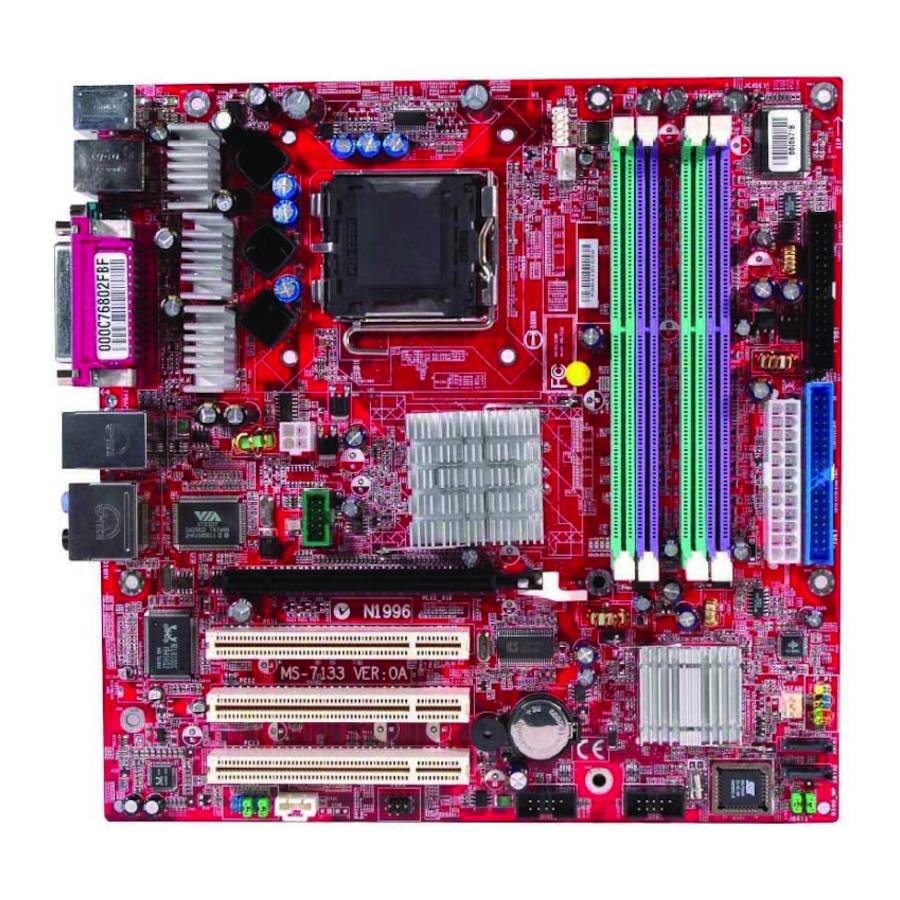
Page 11: Mainboard Layout
M S-7133 M -ATX M ainboard Mainboard Layout 915PM4/915GM4/915GVM4/915GLM4/915PLM4 (MS-7133) v1.X M-ATX Mainboard... -
Page 12: Packing Contents
Getting Started Packing Contents MSI Driver/Utility CD Back IO Shield MSI motherboard User’s Guide... -
Page 13: Chapter 2. Hardware Setup
Chapter 2. Hardware Setup Hardware Setup This chapter tells you how to install the CPU, memory modules, and expansion cards, as well as how to setup the jump- ers on the mainboard. Also, it provides the instructions on connect- ing the peripheral devices, such as the mouse, keyboard, etc. While doing the installation, be careful in holding the compo- nents and follow the installation procedures. -
Page 14: Quick Components Guide
M S-7133 M -ATX M ainboard Quick Components Guide J1394, p.2-20 (Optional) Back Panel I/O, p.2-10 PCI Express x16, p.2-22 PCI Slots, p.2-23 JAUD1, p.2-18 CPUFAN1, CPU, p.2-14 p.2-3 DDR DIMMs, JCOM1, JPW1, p.2-7 p.2-19 p.2-9 JAUX1, JIR1, JUSB1 p.2-17 p.2-20 JUSB2, p.2-19... -
Page 15: Central Processing Unit: Cpu
CPU, make sure to install the heat sink/cooler to prevent overheating. If you do not have the CPU, contact your dealer to purchase and install them before turning on the computer. For the latest information about CPU, please visit http://www.msi.com. tw/program/products/mainboard/mbd/pro_mbd_cpu_support.php. MSI Reminds You... -
Page 16: Cpu, Heatsink & Fan Installation
M S-7133 M -ATX M ainboard CPU, Heatsink & Fan Installation W hen you are installing the CPU, make sure the CPU has a heat sink/ cooler fan attached on the top to prevent overheating. If you do not have the heat sink/cooler fan, contact your dealer to purchase and install them before turning on the computer. - Page 17 5. Lift the load lever up and open the load plate. 7. Visually ins pect if the CPU is seated well into the socket. If not, take out the CPU with purely verti- cal motion and reload it again. Hardware Setup 6.
- Page 18 MSI Reminds You... 1. Confirm if your CPU heatsink/cooler is firmly installed before turning on your system. 2. Check the information in PC Health Status of H/W Monitor in BIOS (refer to p.3-20 for details) for the CPU temperature.
-
Page 19: Memory
The mainboard provides 4 slots for 184-pin DDR SDRAM DIMM (Double In-Line Memory Module) modules and supports the memory size up to 4GB. You can install DDR 333/400 modules on the DDR DIMM slots (DIMM 1~4). For the updated supporting memory modules, please visit http://www.msi. com.tw/program/products/mainboard/mbd/pro_mbd_trp_list.php. DDR DIMM Slots... -
Page 20: Dimm Module Combination
The plastic clip at each side of the DIMM slot will automatically close. MSI Reminds You... You can barely see the golden finger if the module is properly inserted in the socket. -
Page 21: Power Supply
This 12V power connector is used to provide power to the CPU. JPW1 MSI Reminds You... 1. These two connectors connect to the ATX power supply and hav e to work together to ens ure s table operation of the mainboard. -
Page 22: Back Panel
M S-7133 M -ATX M ainboard The back panel provides the following connectors: M ou se IEEE1394 Keyboard COM port USB Ports Mouse/Keyboard Connector The mainboard provides a standard PS/2 nector for attaching a PS/2 keyboard directly into this connector. The connector location and pin assign- ments are as follows: PS/2 Mouse / Keyboard (6-pin Female) -
Page 23: Serial Port Connector
Serial Port Connector The mainboard offers one 9-pin male DIN connector as the serial port. The port is a 16550A high speed communication port that sends/receives 16 bytes FIFOs. You can attach a serial mouse or other serial devices directly to the connector. -
Page 24: Lan (Rj-45) Jack
M S-7133 M -ATX M ainboard LAN (RJ-45) Jack The mainboard provides 1 standard RJ-45 jack for connection to single Local Area Network (LAN). This Giga-bit LAN enables data to be transferred at 1000, 100 or 10Mbps. You can connect a network cable to it. RJ-45 LAN Jack Audio Port Connectors The left 3 audio jacks are for 2-channel mode for stereo speaker output:... -
Page 25: Parallel Port Connector: Lpt1
Parallel Port Connector: LPT1 The mainboard provides a 25-pin female centronic connector as LPT. A parallel port is a standard printer port that supports Enhanced Parallel Port (EPP) and Extended Capabilities Parallel Port (ECP) mode. Pin Definition SIGNAL DESCRIPTION STROBE Strobe DATA0 Data0... -
Page 26: Connectors
Monitor chipset on-board, you must use a specially designed fan with speed sensor to take advantage of the CPU fan control. CPUFAN1 MSI Reminds You... 1. Always consult the vendors for proper CPU cooling fan. 2. Please refer to the recommended CPU fans at Intel website. -
Page 27: Hard Disk Connector: Ide1
Master and a Slave drive. You must configure second hard drive to Slave mode by setting the jumper accordingly. MSI Reminds You... If you install two hard disks on cable, you must configure the second drive to Slave mode by setting its jumper. Refer to the hard disk documentation supplied by hard disk vendors for jumper setting instructions. -
Page 28: Serial Ata Hdd Connectors: Sata1 & Sata2
SATA1 SATA2 Serial ATA cable Connect to serial ATA ports MSI Reminds You... Please do not fold the serial ATA cable in a 90-degree angle, which will cause the loss of data during the transmission. 2-16 SATA1/SATA2 Pin Definition... -
Page 29: Front Panel Connector: Jf_P1
Front Panel Connector: JF_P1 The mainboard provides one front panel connectors for electrical con- nection to the front panel switches and LEDs. JF_P1 is compliant with Intel Front Panel I/O Connectivity Design Guide. JF_P1 Pin Definition SIGNAL HD_LED_P FP PWR/SLP HD_LED_N FP PWR/SLP RST_SW_N... -
Page 30: Front Panel Audio Connector: Jaud1
SENSE1_RETIRN SENSE_SEND PORT 2L SENSE2_RETIRN MSI Reminds You... If you don’t want to connect to the front audio header, pins 5 & 6, 9 & 10 have to be jumpered in order to have signal output directed to the rear audio ports. -
Page 31: Serial Port Connector: Jcom1
Serial Port Connector: JCOM1 The mainboard offers one serial port JCOM1. It is 16550A high speed commu- nication ports that senda/receivea/ 16 bytes FIFOs. You can attach a serial mouse or other serial device directly to it. 10 9 JCOM1 Front USB Connectors: JUSB1 &... -
Page 32: Ieee 1394 Connectors: J1394 (Optional)
M S-7133 M -ATX M ainboard IEEE 1394 Connectors: J1394 (optional) The mainboard provides one 1394 pin headers that allow you to connect IEEE 1394 ports via an external IEEE1394 bracket. J1394 IrDA Infrared Module Header: JIR1 The connector allows you to connect to IrDA Infrared module. You must configure the setting through the BIOS setup to use the IR function. -
Page 33: Jumpers
The motherboard provides the following jumpers for you to set the computer’s function. This section will explain how to change your motherboard’s function through the use of jumpers. BIOS Flash Jumper: BIOS_WP This jumper is used to lock or unlock the boot block area on BIOS. W hen unlocked, the BIOS boot block area can be updated. -
Page 34: Slots
4.0 GB/s over a PCI Express x16 lane for graphics controllers. PCI Express x16 slot MSI Reminds You... 1. The PCI Express x16 slot also supports ADD2 interface card when it is presented on PCI Express x16 slot. -
Page 35: Pci (Peripheral Component Interconnect) Slots
PCI (Peripheral Component Interconnect) Slots The PCI slots allow you to insert the expansion cards to meet your needs. W hen adding or removing expansion cards, make sure that you unplug the power supply first. Meanwhile, read the documentation for the expansion card to make any necessary hardware or software settings for the expansion card, such as jumpers, switches or BIOS configuration. -
Page 36: Chapter 3. Bios Setup
² You want to change the default settings for customized features. MSI Reminds You... 1. The items under each BIOS category described in this chap- te r a re u nde r c ont inu ous upd ate fo r b ette r s y s t em performance. -
Page 37: Entering Setup
M S-7133 M -ATX M ainboard Power on the computer and the system will start POST (Power On Self Test) process. W hen the message below appears on the screen, press <DEL> key to enter Setup. DEL: Setup Menu TAB: Logo If the message disappears before you respond and you still wish to enter Setup, restart the system by turning it OFF and On or pressing the RESET button. -
Page 38: Control Keys
The preset Optimal Defaults of the BIOS setup program provide optimal perfor- mance settings for all devices and the system. MSI Reminds You... The items under each BIOS category described in this chapter are under continuous update for better system performance. -
Page 39: The Main Menu
M S-7133 M -ATX M ainboard The Main Menu Once you enter AMIBIOS NEW SETUP UTILITY, the Main Menu will appear on the screen. Use arrow keys to move among the items and press <Enter> to enter the sub-menu. Standard CMOS Features Use this menu for basic system configurations, such as time, date etc. - Page 40 BIOS Setup Load Fail-Safe Defaults Use this menu to load the default values set by the BIOS vendor for stable system performance. Load Optimized Defaults Use this menu to load the default values set by the mainboard manufacturer specifically for optimal performance of the mainboard. BIOS Setting Password Use this menu to set the password for BIOS.
-
Page 41: Standard Cmos Features
M S-7133 M -ATX M ainboard Standard CMOS Features The items in Standard CMOS Features Menu includes some basic setup items. Use the arrow keys to highlight the item and then use the <+> or <-> keys to select the value you want in each item. Date (MM:DD:YY) This allows you to set the system to the date that you want (usually the current date). - Page 42 LBA/Large Mode This item allows you to enable or disable the LBA (Logical Block Address, the logical block size in hard disk) mode. Setting options: [Auto], [Disabled]. DM A M ode This item allows you to enable or disable the DMA (Direct Memory Access) mode.
-
Page 43: Advanced Bios Features
M S-7133 M -ATX M ainboard Advanced BIOS Features Quick Boot Setting the item to [Enabled] allows the system to boot within 5 seconds since it will skip some check items. Available options: [Enabled], [Disabled]. Boot Sector Protection This function protects the BIOS from accidental corruption by unauthorized users or computer viruses. - Page 44 MSI Reminds You... Enabling the functionality of Hyper-Threading Technology for your computer system requires ALL of the following platform Components: * CPU: An Intel * Chipset: An Intel * BIOS: A BIOS that supports HT Technology and has it enabled;...
- Page 45 These items allow you to set the sequence of boot devices where AMIBIOS attempts to load the operating system. MSI Reminds You... Available settings for “1st/2nd/3rd Boot Device” vary depending on the bootable devices you have installed. For example, if you did not install a floppy drive, the setting “Floppy”...
-
Page 46: Advanced Chipset Features
Advanced Chipset Features MSI Reminds You... Change these settings only if you are familiar with the chipset. Configure DRAM Timing by SPD Selects whether DRAM timing is controlled by the SPD (Serial Presence Detect) EEPROM on the DRAM module. Setting to [Auto By SPD] enables DRAM timings and the following related items to be determined by BIOS based on the configu- rations on the SPD. -
Page 47: Integrated Peripherals
M S-7133 M -ATX M ainboard Integrated Peripherals USB Controller This setting is used to enable/disable the onboard USB host controller. Setting options: [Disabled], [Enabled]. USB Device Legacy Support Set to [Enabled] if you need to use any USB 1.1/2.0 device in the operating system that does not support or have any USB 1.1/2.0 driver installed, such as DOS. - Page 48 Setting options: [Enabled], [Disabled]. Onboard Audio Controller This item is used to enable or disable the onboard Azalia (Audio Codec) controller. Selecting [Enabled] allows the mainboard to enable the onboard Azalia controller. Disable the function if you want to use other controller cards to connect an audio device.
- Page 49 M S-7133 M -ATX M ainboard This field specifies the base I/O port address of the onboard parallel port. Selecting [Auto] allows AMIBIOS to automatically determine the correct base I/O port address. Settings: [378], [278], [3BC] and [Disabled]. Parallel Port M ode This item selects the operation mode for the onboard parallel port: [ECP], [Normal] or [Bi-Dir].
-
Page 50: Power Management Features
Power Management Features MSI Reminds You... S3-related functions described in this section are available only when your BIOS supports S3 sleep mode. ACPI Function This item is to activate the ACPI (Advanced Configuration and Power Manage- ment Interface) Function. If your operating system is ACPI-aware, such as Windows 98SE/2000/ME/XP, select [Enabled]. - Page 51 M S-7133 M -ATX M ainboard [20], [30], [40], [50], [60]. Power Button Function This feature allows users to configure the Power Button function. Settings are: [Power Off] [Suspend] Restore on AC Power Loss This setting specifies whether your system will reboot after a power failure or interrupt occurs.
- Page 52 Time (HH:MM:SS) 00 ~ 23 : 00 ~ 59 : 00 ~ 59 MSI Reminds You... If you have changed this setting, you must let the system boot up until it enters the operating system, before this function will work.
-
Page 53: Pnp/Pci Configurations
M S-7133 M -ATX M ainboard PNP/PCI Configurations This section describes configuring the PCI bus system and PnP (Plug & Play) feature. PCI, or Peripheral Component Interconnect, is a system which allows I/O devices to operate at speeds nearing the speed the CPU itself uses when communicating with its special components. - Page 54 PCI Latency Timer This item controls how long each PCI device can hold the bus before another takes over. W hen set to higher values, every PCI device can conduct transac- tions for a longer time and thus improve the effective PCI bandwidth. For better PCI performance, you should set the item to higher values.
-
Page 55: H/W Monitor
M S-7133 M -ATX M ainboard H/W Monitor This section shows the status of your CPU, fan, overall system status, etc. Monitor function is available only if there is hardware monitoring mechanism CPU Shutdown Temperature If the CPU temperature reaches the limit preset in the next setting, the system will shutdown automatically. - Page 56 CPU FAN PIN Select If you enable the CPU Smart Fan Target Temp Select, this item is available for you to choose the CPU fan pin number of your system. Be sure to select the correct pin number identical to the pin of the CPU fan you purchase. Setting options: [3 PINS], [4 PINS].
-
Page 57: Cell Menu
These two items show the current clocks of CPU & DDR memory frequency. Read-only. Spread Spectrum W hen the motherboard’s clock generator pulses, the extreme values (spikes) of the pulses creates EMI (Electromagnetic Interference). The Spread Spectrum function reduces the EMI generated by modulating the pulses so that the spikes of the pulses are reduced to flatter curves. - Page 58 DDR voltage for long-term purpose is NOT recommended. MSI Reminds You... The settings shown in different color in CPU Voltage, DDR Volt- age and NB Voltage help to verify if your setting is proper for your system.
-
Page 59: Bios Setting Password
M S-7133 M -ATX M ainboard BIOS Setting Password W hen you select this function, a message as below will appear on the screen: Type the password, up to six characters in length, and press <Enter>. The password typed now will replace any previously set password from CMOS memory. -
Page 60: Load Fail-Safe/Optimized Defaults
BIOS Setup Load Fail-Safe/Optimized Defaults The two options on the main menu allow users to restore all of the BIOS settings to the default Fail-Safe or Optimized values. The Optimized Defaults are the default values set by the mainboard manufacturer specifically for optimal performance of the mainboard. -
Page 61: Chapter 4. Itroduction To Realtek Alc880
Chapter 4. Introduction to Chapter 2. Hardware Setup Chapter 4. Itroduction to DigiCell Realtek ALC880 The mainboard is equipped with Realtek ALC880 chip, which provides sup- port for 8-channel audio output, including 2 Front, 2 Rear, 2 Side, 1 Center and 1 Subwoofer channel. -
Page 62: Installing The Realtek Hd Audio Driver
1. Insert the companion CD into the CD-ROM drive. The setup screen will auto- matically appear. 2. Click Realtek HD Audio Driver. MSI Reminds You... The HD Audio Configuration update to enhance audio applications. Hence, the program screens shown here in this appendix may be slightly different from the latest software utility and shall be held for reference only. - Page 63 3. Click Next to install the Realtek High Definition Audio Driver. 4. Click Finish to restart the system. Introduction to Realtek ALC 880 Clic k he r e Se le ct this o ptio n Clic k he r e 4 - 3...
-
Page 64: Software Configuration
M S-7133 M -ATX M ainboard Software Configuration After installing the audio driver, you are able to use the 2-, 4-, 6- or 8- channel audio feature now. Click the audio icon from the system tray at the lower-right corner of the screen to activate the HD Audio Configuration. It is also available to enable the audio driver by clicking the Azalia HD Sound Effect Manager from the Control Panel. -
Page 65: Sound Effect
Sound Effect Here you can select a sound effect you like from the Environment list. You may choose the provided sound effects, and the equalizer will adjust automatically. If you like, you may also load an equalizer setting or make an new equalizer setting to save as an new one by using the “Load EQ Setting”... - Page 66 M S-7133 M -ATX M ainboard Equalizer Selection Equalizer frees users from default settings; users may create their owned preferred settings by utilizing this tool. 10 bands of equalizer, ranging from 100Hz to 16KHz. Save The settings are saved permanently for future Enable / Disable To disable, you can temporarily stop the...
- Page 67 Frequently Used Equalizer Setting Realtek HD Audio Sound Manager provides you certain optimized equalizer settings that are frequently used for your quick enjoyment. [How to Use It] Other than the buttons “Pop” “Live” “Club” & “Rock” shown on the page, to pull down the arrow in “Others”...
-
Page 68: Mixer
Realtek HD Audio rear output or Realtek HD Audio front output items. MSI Reminds You... Before set up, please make sure the playback devices are well plugged in the jacks on the rear or front panel. The Realtek HD Audio front output item will appear after you pluging the speakers into the jacks on the front panel. - Page 69 W hen you are playing the first audio source (for example: use W indows Media Player to play DVD/VCD), the output will be played from the rear panel, which is the default setting. Then you must to select the Realtek HD Audio front output from the scroll list first, and use a different program to play the second audio source (for example: use W inamp to play MP3 files).
- Page 70 M S-7133 M -ATX M ainboard 3. Playback control Tool Mute M u te You may choose to mute single or multiple volume controls or to completely mute sound output. Tool Show the following volume control This is to let you freely decide which volume control items to be displayed, total 13 items to be chosen.
- Page 71 4. Recording control Tool Tool Show the following volume controls This is to let you freely decide which volume control items to be displayed. Advanced controls. Advanced control is a “Microphone Boost” icon. Once this item is checked, you will find “advanced” icon beside “Front Pink In” & “Mic Volume”.
- Page 72 You may control the microphone volume by Mic Volume or front mic-in on the mixer. MSI Reminds You... Only the speakers that plugged into the Line-Out jack (the green ne) on the back panel will be functional when you intend to listen to the audio that has been recorded from the microphone.
-
Page 73: Audioio
AudioIO In this tab, you can easily configure your multi-channel audio function and speakers. You can choose a desired multi-channel operation here. a. Headphone for the common headphone b. 2CH Speaker for Stereo-Speaker Output c. 4CH Speaker for 4-Speaker Output Realtek HD Audio Manager frees you from default speaker settings. - Page 74 M S-7133 M -ATX M ainboard Correct M essage Assume to plug a headphone in the Green jack at back panel. The icon beside green jack become visible and the dialogue “connected device” pops up. Check the headphone, then click OK. As soon as OK is clicked, the icon beside green jack becomes “headphone”...
- Page 75 Global Connector Settings Click to access global connector settings. 1. M ute rear panel when front headphone plugged in (option) Once this item is checked, whenever front headphone is plugged, the music that is playing from the back panel, will be stopped. 2.
- Page 76 M S-7133 M -ATX M ainboard S/PDIF Short for Sony/Philips Digital Interface, a standard audio file transfer format. S/ PDIF allows the transfer of digital audio signals from one device to another without having to be converted first to an analog format. Maintaining the viability of a digital signal prevents the quality of the signal from degrading when it is converted to analog.
- Page 77 Introduction to Realtek ALC 880 Test Speakers You can select the speaker by clicking it to test its functionality. The one you select will light up and make testing sound. If any speaker fails to make sound, then check whether the cable is inserted firmly to the connector or replace the bad speakers with good ones.
-
Page 78: Microphone
M S-7133 M -ATX M ainboard Microphone In this tab you may set the function of the microphone. Select the Noise Suppression to remove the possible noise during recording, or select Acoustic Echo Cancelltion to cancel the acoustic echo druing recording. Also, please use the drop-down list to choose the recording source from Realtek HD Audio real input or Realtek HD Audio front input. -
Page 79: 3D Audio Demo
Introduction to Realtek ALC 880 3D Audio Demo In this tab you may adjust your 3D positional audio before playing 3D audio applications like gaming. You may also select different environment to choose the most suitable environment you like. 4-19... -
Page 80: Information
M S-7133 M -ATX M ainboard Information In this tab it provides some information about this HD Audio Configuration utility, including Audio Driver Version, DirectX Version, Audio Controller & Audio Codec. You may also select the language of this utility by choosing from the Language list. Also there is a selection Show icon in system tray. - Page 81 Before you begin using the front panel function, please complete the follow- ing steps: 1. Please install the pin headers of the front panel according to page 2-18. 2. Select AC97 or Azalia in the BIOS setting (page 3-11). 3. If you are using Azalia setting, the microphone function on the front panel is fixed, but the headphone jack will auto detect the device you connect and pop-up the selection window.
-
Page 82: Using 2-, 4-, 6- & 8- Channel Audio Function
M S-7133 M -ATX M ainboard Using 2-, 4-, 6- & 8- Channel Audio Function Connecting the Speakers W hen you have set the Multi-Channel Audio Function mode properly in the software utility, connect your speakers to the correct phone jacks in accordance with the setting in software utility. - Page 83 n 4-Channel M ode for 4-Speaker Output 4-Channel Analog Audio Output Line In Line Out (Front channels) Line Out (Rear channels) Line Out (Center and Subwoofer channel, but no functioning in this mode) S/PDIF Out-Optical(in 7.1CH / 5.1CH) Introduction to Realtek ALC 880 Description: Connect two speakers to back panel’s Line Out connector and...
- Page 84 M S-7133 M -ATX M ainboard n 6-Channel M ode for 6-Speaker Output 6-Channel Analog Audio Output Line In Line Out (Front channels) Line Out (Rear channels) Line Out (Center and Subwoofer channel) S/PDIF Out-Optical(in 7.1CH / 5.1CH) 4-24 Description: Connect two speakers to back panel’s Line Out connector, two speakers to the rear-channel...
- Page 85 n 8-Channel M ode for 8-Speaker Output 8-Channel Analog Audio Output Line Out (Side channels) Line Out (Front channels) Line Out (Rear channels) Line Out (Center and Subwoofer channel) Optical SPDIF jack Introduction to Realtek ALC 880 Description: Connect two speakers to back panel’s Line Out connector, two speakers to the rear-channel, two speakers to the c enter/...
-
Page 86: Chapter 5. Introduction To Digicell
Chapter 4. Introduction to DigiCell Introduction to DigiCell DigiCell, the most useful and powerful utility that MSI has spent much research and efforts to develop, helps users to monitor and configure all the integrated peripherals of the system, such as audio program, power management, MP3 files management and communication / 802.11g W LAN... -
Page 87: Main
Introduction: Click on each icon appearing above to enter the sub-menu to make further configuration. M SI Click on this button to link to MSI website: http://www.msi.com.tw. Quick Guide Click on this button and the quick guide of DigiCell will be displayed for you to review. - Page 88 Power on Agent In this sub-menu, you can configure date, time and auto-executed programs of the power-on, power-off and restarting features. MSI Reminds You... Click on back button in every sub-menu and it will bring you back to the main menu.
-
Page 89: H/W Diagnostic
In the H/W Diagnostic sub-menu, you can see the information, status and note of each DigiCell. You may double check the connection and installation of the item marked as gray. You may also click on the Mail to MSI button to send your questions or suggestions to MSI’s technical support staff. -
Page 90: Communication
In the Communication sub-menu, you can see the status of all the LAN / W LAN / Bluetooth on the screen if the hardware is installed. The first icon indicates the onboard LAN on your system, the second icon indicates the wireless LAN status, and the third one is the information about the bluetooth on your system. -
Page 91: Software Access Point
M S-7133 M -ATX M ainboard M SI Feature Software Access Point In the Software Access Point sub-menu, you can see the communication status on your system and choose the desired software access point mode by clicking on the desired icon, in which the default settings are configured for your usage. The default software access point mode is set to WLAN Card M ode. -
Page 92: Access Point Mode
Access Point Mode Click on “Setting” button of the Access Point Mode and the following screen will display. IP Sharing Click on this icon to enable/disable the IP sharing. The default of this setting is disabled. Disabled. Enabling/disabling IP sharing depends on the different situation. For example: 1. -
Page 93: Wlan Card Mode
M S-7133 M -ATX M ainboard M SI Feature enable this feature, only PCs with MAC address located in Association Control List can connect to the wireless LAN. M AC Address MAC stands for Media Access Control. A MAC address is the hardware address of a device connected to a network. -
Page 94: Live Update
BIOS/VGA Driver/Utility online so that you don’t need to search for the correct BIOS/driver version throughout the whole W eb site. To use the function, you need to install the “MSI Live Update 3” application. After the installation, the “MSI Live Update 3”... -
Page 95: Mega Stick
M S-7133 M -ATX M ainboard M SI Feature In the MEGA STICK sub-menu, you can configure the settings of MSI MEGA STICK and the media files (*.m3u, *.mp3, *.wav, *.cda, *.wma) on your system. Basic Function Here you can edit your own play list with the buttons “load”, “save”, “delete”, “shuttle”, “repeat”... - Page 96 There is also a toolbar for you to execute some basic function, like play, stop, pause, previous/next song, song info and volume adjust. There is also a scroll bar on the top for you to forward/rewind. pause previous stop Right-click on the MP3 file and choose “Info”, a MP3 Info dialogue will pop up to show the information of the file, including the title, artist, album, release year and others.
-
Page 97: Non-Unicode Programs Supported
M S-7133 M -ATX M ainboard M SI Feature Non-Unicode programs supported If you are using an operating system in European languages, and you’d like to play the media files in MEGA STICK with East-Asian languages (such as Chinese, Japanese... etc.), it is possible that the file names display incorrectly. - Page 98 Introduction to DigiCell 3. Then go to the [Advanced] tab and select the language you want to be supported (the language of the filename in the MegaStick) from the drop- down list in the [Language for non-Unicode programs], then click [Apply]. The system will install the necessary components from your Microsoft Setup CD immediately.
-
Page 99: Core Center (For Pentium 4 Cpu)
M S-7133 M -ATX M ainboard M SI Feature Core Center (for Pentium 4 CPU) Click on the Core Center icon in the main menu and the Core Center program will be enabled. CoreCenter is just like your PC doctor that can detect, view and adjust the PC hardware and system status during real time operation. -
Page 100: Left-Wing: Current System Status
Introduction to DigiCell Left-wing: Current system status In the left sub-menu, you can configure the settings of FSB, Vcore, Memory Voltage and AGP Voltage by clicking the radio button next to each item and make it available (the radio button will be lighted as yellow when selected), use the “+” and “-” buttons to adjust, then click “OK”... -
Page 101: Audio Speaker Setting
M S-7133 M -ATX M ainboard M SI Feature Audio Speaker Setting In the Audio Speaker Setting sub-menu, you can configure the multi-channel audio operation, perform speaker test, and choose the environment you prefer while en- joying the music. You can scroll the bar of each equalizer to regulate the current playing digital sound source. - Page 102 Introduction to DigiCell Click on the “Speaker test” button and the following dialogue box will appear: In this Speaker Configuration dialogue box, select the audio configuration which is identical to the audio jack on your mainboard. Once the correct audio configuration is selected, click “Apply”...
-
Page 103: Power On Agent
Click “OK” to restart the computer right away or click “Later” to restart your computer later. MSI Reminds You... Please note that the new setting will not take effect until you restart your computer. -
Page 104: Power Off / Restart
Of course you may use the button “-Delete” to remove the added programs, or you can right-click on the selected program and click Delete. MSI Reminds You... You can also enable the Every turn on function, which will enable the specified program(s) and file(s) every time the Digi Cell utility runs. -
Page 105: Auto Login
M S-7133 M -ATX M ainboard M SI Feature Auto Login Since the Power On function allows the system to power on automatically, you may have to enable this Auto Login function in the following situations: 1. If you are using a computer belonging to a domain in office, and you need to enter your user name &...