Table of Contents
Advertisement
Available languages
Available languages
FCC-B Radio Frequency Interference Statement
This equipment has been tested and found to comply with the limits for a class B digital device, pursuant to part
15 of the FCC rules. These limits are designed to provide reasonable protection against harmful interference
when the equipment is operated in a commercial environment. This equipment generates, uses and can
radiate radio frequency energy and, if not installed and used in accordance with the instruction manual, may
cause harmful interference to radio communications. Operation of this equipment in a residential area is likely
to cause harmful interference, in which case the user will be required to correct the interference at his own
expense.
Notice 1
The changes or modifications not expressly approved by the party responsible for compliance could void the
user's authority to operate the equipment.
Notice 2
Shielded interface cables and A.C. power cord, if any, must be used in order to comply with the emission limits.
VOIR LA NOTICE D'NSTALLATION AVANT DE RACCORDER AU RESEAU.
This device complies with Part 15 of the FCC Rules. Operation is subject to the following two conditions:
(1) this device may not cause harmful interference, and
(2) this device must accept any interference received, including interference that may cause undesired
operation
Micro-Star International
MS-7103
G52-M7103X2
i
Advertisement
Table of Contents

Related Manuals for MSI 661FM3-V Series


Summary of Contents for MSI 661FM3-V Series
- Page 1 FCC-B Radio Frequency Interference Statement This equipment has been tested and found to comply with the limits for a class B digital device, pursuant to part 15 of the FCC rules. These limits are designed to provide reasonable protection against harmful interference when the equipment is operated in a commercial environment.
- Page 2 Copyright Notice The material in this document is the intellectual property of MICRO-STAR INTERNATIONAL. We take every care in the preparation of this document, but no guarantee is given as to the correctness of its contents. Our products are under continual improvement and we reserve the right to make changes without notice. Trademarks All trademarks are the properties of their respective owners.
- Page 3 Safety Instructions 1. Always read the safety instructions carefully. 2. Keep this User Manual for future reference. 3. Keep this equipment away from humidity. 4. Lay this equipment on a reliable flat surface before setting it up. 5. The openings on the enclosure are for air convection hence protects the equipment from overheating. Do not cover the openings.
- Page 4 Table of Content English...1 Deutsch...15 Français ...31 简体中文 ...47 繁體中文 ...61 日本語...75...
- Page 5 ATX mainboard. The 661FM3-V/661GM3-V/648M3-V/648FM3-V Series is based on SiS ® 661FX/GX/648FX/648 & SiS ® 964/964L chipsets for optimal system efficiency. Designed to fit the advanced Intel ® Pentium ® 4/Celeron D processors in 775 pin package, the 661FM3-V/ 661GM3-V/648M3-V/648FM3-V Series delivers a high performance and professional desktop platform solution.
-
Page 6: Specifications
Supports Intel ® Pentium 4/Celeron D processor in the 775-land package l Supports 533MHz, 800MHz FSB l Supports 4 pins CPU Fan Pin-Header with Fan Speed Control (For the latest information about CPU, please visit http://www.msi.com.tw/program/products/mainboard/mbd/pro_mbd_cpu_support.php ) Chipset l SiS ® 648FX/648/661GX/FX Chipset - Integrated graphic controller (661FX/661GX only) - Support DDR333/400 SDRAM l SiS ®... - Page 7 On-Board Peripherals l On-Board Peripherals include: - 1 floppy port supports 1 FDD with 360K, 720K, 1.2M, 1.44M and 2.88Mbytes. - 2 serial ports, Com1 on Rear IO, JCOM2 via pin header (IO bracket is optional) - 1 parallel port supports SPP/EPP/ECP mode. - 8 USB 2.0/1.1 ports (Rear * 4/ Front * 4).
-
Page 8: Rear Panel
If you do not have the CPU, contact your dealer to purchase and install them before turning on the computer. For the latest information about CPU, please visit http://www.msi.com.tw/program/products/mainboard/mbd/pro_mbd_cpu_support.php. Example of CPU Core Speed Derivation Procedure CPU Clock... -
Page 9: Memory Speed/Cpu Fsb Support Matrix
Memory Speed/CPU FSB Support Matrix Memory DDR 200 400 MHz 533 MHz LGA775 CPU and Cooler Installation (CPU clip is optional) When you are installing the CPU, make sure the CPU has a cooler attached on the top to prevent overheating. - Page 10 2GB. To operate properly, at least one DIMM module must be installed. (For the updated supporting memory modules, please visit http://www.msi.com.tw/program/products/mainboard/mbd/pro_mbd_trp_list.php ) Install at least one DIMM module on the slots. Memory modules can be installed on the slots in any order.
-
Page 11: Power Supply
Power Supply The mainboard supports ATX power supply for the power system. Before inserting the power supply connector, always make sure that all components are installed properly to ensure that no damage will be caused. A 300W or above power supply is suggested. ATX 20-Pin Power Connector: CONN1 This connector allows you to connect to an ATX power supply. -
Page 12: Fan Power Connectors: Cpufan1/Chsfan1
+12V, the black wire is Ground and should be connected to GND. MSI Reminds You... Always consult the vendors for proper CPU cooling fan. IDE Connectors: IDE1 & IDE2... -
Page 13: Front Panel Connectors: Jfp1 & Jfp2
Intel ® Front Panel I/O Connectivity Design Guide. MSI Reminds You... If you do not want to connect to the front audio header, pins 5 & 6, 9 & 10 have to be jumpered in order to have signal output directed to the rear audio ports. -
Page 14: Serial Port Connector: Jcom2
Serial Port Connector: JCOM2 The mainboard offers another serial port JCOM2. It is 16550A high speed communication port that sends/receives 16 bytes FIFOs. The MSI JCOM2 cable is optional. SIGNAL DESCRIPTION Data Carry Detect SOUT Receive Data Transmit Data Request To Send Ring Indicate Serial ATA HDD Connectors: SATA1 &... -
Page 15: Agp (Accelerated Graphics Port) Slot
MSI Reminds You... You can clear CMOS by shorting 1-2 pin while the system is off. Then return to 2-3 pin position. Avoid clearing the CMOS while the system is on; it will damage the mainboard. AGP (Accelerated Graphics Port) Slot The AGP slot allows you to insert the AGP graphics card. -
Page 16: Bios Setup
BIOS Setup Power on the computer and the system will start POST (Power On Self Test) process. When the message below appears on the screen, press <DEL> key to enter Setup. If the message disappears before you respond and you still wish to enter Setup, restart the system by turning it OFF and On or pressing the RESET button. -
Page 17: Frequency/Voltage Control
Load Optimized Defaults Use this menu to load the default values set by the mainboard manufacturer specifically for optimal performance of the mainboard. BIOS Setting Password Use this menu to set BIOS setting Password. Save & Exit Setup Save changes to CMOS and exit setup. Exit Without Saving Abandon all changes and exit setup. - Page 18 PCI slots to minimize the electromagnetic interference (EMI). Spread Spectrum When the motherboard’s clock generator pulses, the extreme values (spikes) of the pulses creates EMI (Electromagnetic Interference). The Spread Spectrum function reduces the EMI generated by modulating the pulses so that the spikes of the pulses are reduced to flatter curves.
- Page 19 SiS ® 661FX/GX/648FX/648 und SiS ® 964/964L Chipsätzen und ermöglicht so ein optimales und effizientes System. Entworfen um die fortschrittlichen Intel ® Pentium ® 4/Celeron D Prozessoren im 775 Pin Package aufzunehmen, stellt das 661FM3-V/661GM3-V/648M3-V/ 648FM3-V Series die ideale Lösung zum Aufbau eines professionellen Hochleistungsdesktopsystems dar.
-
Page 20: Spezifikationen
Verfügbare Bandbreite bis zu 3.2 GB/s (DDR 400) l Unterstützt 128Mb, 256Mb oder 512MB DDR Bauweise (Um den letzten Stand bezüglich der unterstützten Speichermodule zu erhalten, besuchen Sie bitte http://www.msi.com.tw/program/products/mainboard/mbd/pro_mbd_trp_list.php ) Schnittstellen l Ein AGP Sockel l Zwei PCI Sockel (32-Bit V2.3 Master PCI, 3,3V/5V PCI Bus unterstützt). - Page 21 Peripherieanschlüsse onboard l hierzu gehören: - 1 Anschluss für 1 Diskettenlaufwerk mit 360 KB, 720 KB, 1,2 MB, 1,44 MB oder 2,88 MB. - 2 Serielle Schnittstellen, COM 1 am hinteren Anschlusspaneel und JCOM2 als Stiftleiste auf dem Board (passendes Slotblech optional). - 1 Parallele Schnittstelle, die die Betriebsmodi SPP/EPP/ECP unterstützt.
-
Page 22: Hinteres Anschlusspaneel
über keinen Kühler, setzen Sie sich bitte mit Ihrem Händler in Verbindung, um einen solchen zu erwerben und danach zu installieren, bevor Sie Ihren Computer anschalten. (Um die neuesten Informationen zu unterstützten Prozessoren zu erhalten, besuchen Sie bitte http://www.msi.com.tw/program/products/mainboard/mbd/pro_mbd_cpu_support.php) Beispiel zur Ermittlung des Kerntaktes Wenn... - Page 23 Tabelle Speichergeschwindigkeit/unterstützter CPU FSB Speicher DDR 200 400 MHz 533 MHz Einbau von CPU und Kühler beim LGA775 (Der CPU Clip ist optional) Wenn Sie die CPU einbauen, stellen Sie bitte sicher, dass Sie auf der CPU einen Kühlkörper mit aktiven Prozessorlüfter anbringen, um Überhitzung zu vermeiden.
- Page 24 DIMM- Speichermodul eingesetzt sein. (Um den letzten Stand bezüglich der unterstützten Speichermodule zu erhalten, besuchen Sie bitte http://www.msi.com.tw/program/products/mainboard/mbd/pro_mbd_trp_list.php) Setzen Sie mindestens ein Speichermodul in einen Stecksockel. Die Speichermodule können in beliebiger Reihenfolge eingesetzt werden. Gemäß Ihren Anforderungen können Sie entweder...
- Page 25 Volt Stromversorgung Das Mainboard unterstützt zur Stromversorgung ATX Netzteile. Bevor Sie den Netzteilstecker einstecken, stellen Sie stets sicher, dass alle Komponenten ordnungsgemäß eingebaut sind, um Schäden auszuschließen. Es wird ein Netzteil mit 300W oder mehr empfohlen. ATX 20-Pin Stromanschluss: CONN1 Hier können Sie ein ATX Netzteil anschließen.
- Page 26 Draht der positive Pol ist, und mit +12V verbunden werden sollte, der schwarze Draht ist der Erdkontakt und sollte mit GND verbunden werden. MSI weist darauf hin... Bitten Sie stets Ihren Händler um Hilfe bei der Auswahl des geeigneten CPU Kühlers.
- Page 27 Setzen einer Steckbrücke als Slave eingestellt werden. IDE2 kann ebenfalls je ein Master- und ein Slave- Laufwerk verwalten. MSI weist darauf hin... Verbinden Sie zwei Laufwerke über ein Kabel, müssen Sie das zweite Laufwerk im Slave-Modus konfigurieren, indem Sie entsprechend den Jumper setzen. Entnehmen Sie bitte die Anweisungen zum Setzen des Jumpers der Dokumentation der Festplatte, die der Festplattenhersteller zur Verfügung stellt.
- Page 28 Richtlinien des “Intel® Front Panel I/O Connectivity Design Guide”. MSI weist darauf hin... Wenn Sie die vorderen Audioanschlüsse nicht verwenden, müssen die Pins 5 & 6, 9 & 10 mit sog. „Jumpern“ gebrückt werden, um die Signalausgabe auf die hinteren Audioanschlüsse umzuleiten.
- Page 29 Serieller Anschluss: JCOM2 Das Mainboard bietet einen zusätzlichen Seriellen Anschluss JCOM2. Es handelt sich um eine 16550A Hochgeschwindig- keitskommunikationsschnittstelle, die 16 Bytes FIFOs sendet/empfängt. Das MSI JCOM2 Kabel ist optional. SIGNAL BESCHREIBUNG Data Carry Detect SOUT Receive Data Transmit Data...
- Page 30 Sie hierfür JBAT1 (Clear CMOS Jumper - Steckbrücke zur CMOS Löschung). Halten Sie sich an die folgenden Anweisungen, um die Daten löschen: MSI weist darauf hin... Sie können den CMOS löschen, indem Sie die Pins 1-2 verbinden, während das System ausgeschaltet ist.
-
Page 31: Agp (Accelerated Graphics Port) Slot
AGP (Accelerated Graphics Port) Slot Der AGP Slot ermöglicht den Einsatz einer AGP Grafikkarte. AGP ist eine Schnittstellen- spezifikation, die gemäß den Anforderungen von 3D Grafiken an den Datendurchsatz entwickelt wurde. Mit ihr hat die direkte Anbindung des Grafikkontrollers an den Hauptspeicher über einen mit 66MHz getakteten 32-Bit Kanal Einzug gehalten. -
Page 32: Bios Setup
BIOS Setup Nach dem Einschalten beginnt der Computer den POST (Power On Self Test - Selbstüberprüfung nach Anschalten). Sobald die Meldung unten erscheint, drücken Sie die Taste <Entf>(<Del>), um das Setup aufzurufen. Wenn die Nachricht verschwindet, bevor Sie reagieren und Sie möchten immer noch ins Setup, starten Sie das System neu, indem Sie es erst AUS- und danach wieder ANSCHALTEN, oder die “RESET”-Taste am Gehäuse betätigen. -
Page 33: Frequency/Voltage Control
Power Management Setup Verwenden Sie dieses Menü, um die Einstellungen für die Stromsparfunktionen vorzunehmen. PNP/PCI Configurations Dieser Eintrag erscheint, wenn Ihr System Plug and Play- Geräte am PCI-Bus unterstützt. H/W Monitor Dieser Eintrag gibt den Status Ihrer CPU, Lüfter und Warnungen bezüglich des Gesamtstatus Ihres Systems wider. - Page 34 Adjust CPU FSB Frequency Erlaubt Ihnen, die Taktfrequenz des CPU Front Side Bus (FSB - in MHz) einzustellen und den Prozessor zu übertakten, indem Sie den externen CPU- Takt (FSB Takt) anheben. Wählen Sie zwischen 133MHz, 137MHz, 140MHz, 200 MHz, 206MHz, 210MHz (ROM Table) Adjust CPU Ratio Hier können Sie den CPU-Taktrelation (Taktmultiplikator) angeben.
- Page 35 Introduction Félicitations, vous venez d’acquérir une carte mère M-ATX 661FM3-V/661GM3-V/648M3-V/ 648FM3-V Series (MS-7103 v1.X). Les 661FM3-V/661GM3-V/648M3-V/648FM3-V Series sont basées sur les chipsets SiS ® 661FX/GX/648FX/648 & SiS ® 964/964L offrant un système très performant.. La carte fonctionne avec les processeurs Intel ® Pentium ® 4/Celeron D (LGA 775), les 661FM3-V/661GM3-V/648M3-V/648FM3-V Series sont très performantes et offrent une...
- Page 36 Supporte les ventilateurs équipés d’un connecteur 4 broches permettant de contrôler la vitesse de rotation des ventilateurs (Pour les dernières mises à jours concernant les CPU, vous pouvez visiter : http://www.msi.com.tw/program/products/mainboard/mbd/pro_mbd_cpu_support.php.) Chipset l Chipset SiS ® 648FX/648/661GX/FX - Contrôleur graphique intégré (661FX/661GX seulement) - Supporte la SDRAM DDR333/400 l Chipset SiS ®...
- Page 37 Périphériques Intégrés l Périphériques Intégrés Inclus : - 1 port floppy supportant 1 FDD avec 360K, 720K, 1.2M, 1.44M et 2.88Mbytes. - 2 ports série, Com1 sur l’arrière IO, JCOM2 par pin header (le bracket IO est optionnel) - 1 port parallèle supportant les modes SPP/EPP/ECP - 8 ports USB 2.0/1.1 (Arrière * 4/ Avant * 4) - 1 port audio (Line-In/Line-Out/Mic) - 1 RJ45 LAN jack.
-
Page 38: Panneau Arrière
éviter la surchauffe. Si vous ne savez pas quel ventilateur utiliser, veuillez contacter votre revendeur avant de mettre en marche votre PC. (Pour une mise à jour sur les CPU, veuillez visiter http://www.msi.com.tw/program/products/mainboard/mbd/pro_mbd_cpu_support.php) Exemple de Procédure de Dérivation du CPU Core... - Page 39 Aligner les indicateurs de couleur jaune (triangle sur le CPU & sur le clip), et utiliser le clip MSI pour fixer le processeur sur le socket en pratiquant de la façon indiquée sur la photo. Le CPU possède un capot plastique le protégeant. Ne jamais retirer le capot avant que le CPU ne soit installé.
- Page 40 DIMM. (Pour les dernières mises à jours de mémoire supportées, merci de visiter http://www.msi.com.tw/program/products/mainboard/mbd/pro_mbd_trp_list.php) Installer au moins un module DIMM sur les slots. L’installation des modules de mémoires n’a pas de sens particulier.
- Page 41 Alimentation La carte mère supporte les alimentations ATX. Avant de brancher le connecteur d’alimentation, Il faut toujours vous assurer que tous les composants sont bien installés afin de ne pas les endommager. Une alimentation 300W ou supérieur est préconisée. Connecteur d’alimentation ATX 20 broches: CONN1 Ce connecteur vous permet de connecter l’alimentation ATX.
- Page 42 +12V et le fil noir connecté au “GND“. Si la carte mère possède un système de gestion intégré, vous devez utiliser un ventilateur ayant ces caractéristiques si vous voulez contrôler le ventilateur du CPU. MSI Vous rappelle... Il faut toujours consulter votre revendeur au sujet du ventilateur. IDE Connecteurs: IDE1/IDE2 La carte mère possède un contrôleur 32-bit Enhanced PCI IDE et Ultra DMA...
- Page 43 ® Front Panel I/O Connectivity Design Guide MSI Vous rappelle... Si vous ne voulez pas connecter l’audio en façade à l’aide des broches 5 & 6, 9 & 10 doivent être recouvertes par un cavalier pour envoyer le signal vers les ports audio à l’arrière. Autrement le connecteur Line-Out à...
- Page 44 Connecteur Port de série: JCOM2 La carte mère offre un autre port de série JCOM2. C’est un port de communication haute vitesse 16550A qui envoie/reçoit 16 bytes FIFOs. Le câble MSI JCOM2 est optionnel. SIGNAL DESCRIPTION Data Carry Detect...
- Page 45 JBAT1 (Cavalier Clear CMOS) pour effacer les données. Suivez les instructions de l’image pour effacer les données. MSI Vous Rappelle... Vous pouvez effacer les données en positionnant le cavalier sur les broches 2-3 quand le PC n’est pas allumé.
- Page 46 Slot AGP (Accelerated Graphics Port) Le slot AGR vous permet de connecter une carte graphique AGP. Cette interface est particulièrement bien adaptée aux applications 3D. Contrôleur 66MHz, 32-bit avec accès direct à la mémoire principale. Le slot supporte les cartes AGP 4x. Slots PCI (Peripheral Component Interconnect) Les slots PCI vous permettent la connexion de cartes d’extension selon vos besoins.
-
Page 47: Page Principale
BIOS Setup Lorsque le PC démarre le processus de POST (Power On Self Test) se met en route. Quand le message ci-dessous apparaît, appuyer sur <DEL> pour accéder au Setup. DEL: Setup F7: Setup Defaults F10: Save & Exit TAB: Logo Si le message disparaît avant que n’ayez appuyé... - Page 48 Frequency/Voltage Control Utiliser ce menu pour configurer vos paramètres de pour le contrôle de la fréquence et du voltage. Load BIOS Defaults Utiliser ce menu pour charger les paramètres par défaut du BIOS are factory settings for system operations. Set Password Utiliser ce menu pour entrer un mot de passe Save &...
-
Page 49: Frequency/Voltage Control
Frequency/Voltage Control Current CPU Clock Cet élément montre la fréquence d’horloge du CPU. lecture uniquement. Adjust DDR Memory Frequency En position [Manual] en mode haute performance, l’utilisateur peut placer une limite artificielle de la fréquence de mémoire. Merci de noter que la mémoire ne pourra pas fonctionner plus vite que la valeur qui lui a été... - Page 50 choisissez Enabled pour réduire les EMI. N’oubliez pas de désactiver cette fonction si vous voulez faire de l’overclocking, afin d’éviter tout problème. Les options : [Disabled], [Enabled].
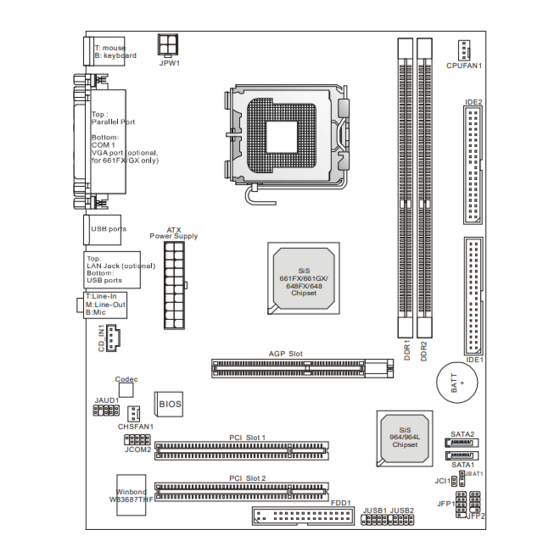
- Page 51 简介 感谢您购买 661FM3-V/661GM3-V/648M3-V/648FM3-V Series(MS-7103 v1.X) micro ATX 主板。 661FM3-V/661GM3-V/648M3-V/648FM3-V Series 是基于 SiS ® 661FX/GX/648FX/648 & SiS ® 964/964L 芯片组,是为 LGA775 针脚封装的 Intel ® Pentium ® 4/Celeron D 处理器量身定做的高 性能主板。661FM3-V/661GM3-V/648M3-V/648FM3-V Series 提供了高性能、专业化的桌面平台 解决方案。 布局 T: mouse B: keyboard JPW1 AT X...
- Page 52 规格 l 支持 LGA775 针脚封装的 Intel ® Pentium 4/Celeron D 处理器 l 支持 533MHz、800MHz FSB l 支持 4 针脚、带有风扇速度控制功能的 CPU 风扇针头 (要了解关于 CPU 的最新信息,请访问 http://www.msi.com.tw/program/products/mainboard/mbd/pro_mbd_cpu_support.php ) 芯片组 l SiS ® 648FX/648/661GX/FX 芯片组 - 集成了显卡控制器(仅对于 661FX/661GX) - 支持 DDR333/400 SDRAM l SiS ® 964/964L 芯片组...
- Page 53 板载周边 l 板载周边包括: - 1 个软驱接口,支持 1 台 360K, 720K, 1.2M, 1.44M 和 2.88 Mbytes 的软驱 - 2 个串行端口,后置接口 Com1,通过针头支持 JCOM2(IO bracket 挡板为选配组件) - 1 个并行端口,支持 SPP/EPP/ECP 模式 - 8 个 USB 2.0 端口(后置* 4/ 前置* 4) - 1 个音频(Line-In/Line-Out/Mic)端口 - 1 个...
-
Page 54: 中央处理器:Cpu
接外围设备的指导,如鼠标,键盘等。安装时,请谨慎拿各零部件并且按照安装说明的步骤进行。 中央处理器:CPU 本主板支持 LGA775 封装的 Intel ® Pentium 4 / Celeron DTM(LGA775)处理器。主板使用的是 LGA775 封装的 CPU 插槽,可使 CPU 安装过程简化。当您在安装 CPU 时,请务必确认您使用的 CPU 带有防过热的散热片和降温风扇。如果您的 CPU 没有散热片和降温风扇,请与销售商联系, 购买或索取以上设备,并在开机之前妥善安装。 要了解关于 CPU 的最新信息,请访问 http://www.msi.com.tw/program/products/mainboard/mbd/pro_mbd_cpu_support.php. CPU 核心速度推导 如果 CPU 时钟频率 核心/总线倍频 那么 CPU 核心频率 内存速度/CPU FSB 支持列表... - Page 55 LGA775 CPU 和风扇的安装 (此 CPU 夹子为选配组件) 当您安装 CPU 时,请确认 CPU 带有散热片和风扇放置在 CPU 顶部,以防止 CPU 过热。如果您 没有散热片和风扇, 请联系经销商以购买和安装。 然而请不要忘记使用一些散热胶涂在 CPU 表面, 使它更好地散热。 请根据以下步骤正确安装 CPU 和风扇。错误的安装可能会引起您 CPU 和主板的损毁。 CPU 底部有一个底座保护片,可保护 CPU 底座避免损害。旋转 CPU,使得针脚 1 的指示 标志(黄色三角形)位于左下角。具体情况要根据 CPU 的包装而定。取 出随带的 CPU 夹子(如右图所示) ,并旋转至与 CPU 相同的方向(针 脚...
- Page 56 内存 主板提供 2 条插槽,可以插入 184-pin 无缓冲的 DDR333/DDR400 DDR SDRAM 内存,支持的最 大容量为 2GB。您至少要安装一条内存在插槽,以保证系统正常工作。 (要了解内存模组支持的更 新,请访问 http://www.msi.com.tw/program/products/mainboard/mbd/pro_mbd_trp_list.php ) 至少要安装一条内存模组在插槽。内存条可以按任何次序被安装。您也可以根据自己的需要,来安 装单面或双面的内存模组。 DDR DIMM 内存条的中央仅有一个缺口。 将 DDR 内存垂直插入 DDR 插槽中,并确保缺口的正确位置。 DIMM 插槽两边的塑料卡口会自动闭合。 Vol t 电源适配器 主板使用 ATX 结构的电源适配器给主板供电。在连接电源适配器之前,请务必确认所有的组件都 已正确安装,并且不会造成损坏。建议您使用功率为 300W 或以上的电源。 ATX 20-Pin 电源接口:CONN1 此接口可连接...
- Page 57 软盘驱动器接口:FDD1 主板提供了一个标准的软盘驱动器接口 FDD,支持 360K, 720K, 1.2M, 1.44M 和 2.88M 的软盘驱动器。 机箱入侵侦测接头:JCI1 此接头连接到 2 针脚的机箱开关接口。若机箱打开了,开关会被短接。系统 GN D C I NT RO 会自动记录状态。要清除警告,您必须进入 BIOS 设置,清除状态。 CD-In 接口:CD_IN1 此接口为 CD-ROM 的音频接口。 风扇电源接口:CPUFAN1/CHSFAN1 CPUFAN1 (处理器风扇)和 CHSFAN1(系统风扇)支持+12V SENSOR CONTROL 的系统散热风扇。当您将接线接到风扇接头时,请注意红色线 SENSOR +12V +12V 为正极,必须接到+12V,而黑色线是接地,必须接到 GND。 CPUFAN1 CHSFAN1 如果您的主机板有系统硬件监控芯片,您必须使用一个特别设...
- Page 58 IDE 接口:IDE1 & IDE2 主板有 2 个 32-bit 增强 PCI IDE 和 Ultra DMA 33/66/100/133 控制器,支持 PIO 模式 0~4, Bus Master 和 Ultra DMA 33/66/100/133 工作模式,且它最多可连接 4 个设备, 例如硬盘、CD-ROM、120MB 软驱和其他设备。 第一个硬盘应该连接到 IDE1 接口。 IDE1 可以连接 1 个 Master ( 主) 设备和 1 个 Slave (从)设备。通过跳线的正确设置,您可以配置第二个硬盘到...
- Page 59 前置 USB 接口:JUSB1/2 主板提供 2 个 USB2.0 的接口 JUSB1、JUSB2。USB 2.0 技术提高数据传输 速度,达到 480Mbps,是 USB1.1 的 40 倍。它可连接高速数据传输速率的 USB 界面周边设备,如 USB HDD、数码相机、MP3 播放器、打印机、调制 解调器等。 微星提醒您... 请注意,VCC 和 GND 的针脚必须安插正确,否则会引起主板的损毁。 串行接口:JCOM2 主板提供另一个 9-pin 公头 DIN 接口作为串行接口 JCOM2,是 16550A 高速通信端口,可收发 16 bytes FIFO,可用来连接串行 鼠标或其它串行设备。微星...
- Page 60 清除 CMOS 跳线:JBAT1 主板上建有一个 CMOS RAM , 其中保存的系统配置数据需要通过一 枚外置电池来维持 。 CMOS RAM 是在每次启动计算机的时候引导操 作系统的。若您想清除保存在 CMOS RAM 中的系统配置信息,可使用 JBAT1 (清除 CMOS 跳线) 清除数据。请按照以下方法清除数据: 微星提醒您... 在系统关闭时,您可通过短接 2-3 针脚来清除 CMOS 数据。然后,返回到 1-2 针短接的状态。请 避免在系统开机时清除 CMOS,这样可能会对主板造成损害。 Clear Data Keep Data...
- Page 61 AGP(加速图形端口)插槽 AGP 插槽可让您插入 AGP 图像卡。AGP 是专为 3D 图形显示而设计的一种接口规范。它为图形 控制器对主内存的直接访问提供一个 66MHz,32-bit 专用通道。本主板支持 4x 的 AGP 卡。 PCI(周边设备连接)插槽 PCI 插槽可安装您所需要的扩展卡。当您在安装或拆卸扩展卡的时候,请务必确认已将电源插头 拔除。同时,请仔细阅读扩展卡的说明文件,安装和设置此扩展卡必须的硬件和软件,比如跳线或 BIOS 设置。 PCI 中断请求队列 IRQ 是中断请求队列和中断请求确认的缩写,将设备的中断信号送到微处理器的硬件列表。PCI 的 IRQ 针脚一般都是连接到如下表所示的 PCI 总线的 INT A# ~ INTD# 引脚: Order1 PCI Slot 1 INT B# PCI Slot 2 INT C# Order2...
- Page 62 BIOS 设置 计算机加电后,系统将会开始 POST (加电自检)过程。当屏幕上出现以下信息时,按<DEL>键 即可进入设定程序。 如果信息在您做出反应前就消失了,而您仍需要进入 Setup,请关机后再开机或按机箱上的 Reset 键, 重启您的系统。您也可以同时按下<Ctrl>、<Alt>和<Delete>键来重启系统。 主页面 Standard CMOS Features(标准 CMOS 特性设定) 使用此菜单可对基本的系统配置进行设定。如时间,日期等。 Advanced BIOS Features(高级 BIOS 特性设定) ® 使用此菜单可对 Award 系统的高级特性进行设定。 Advanced Chipset Features(高级芯片组特性设定) 使用此菜单可以修改芯片组寄存器的值,优化系统的性能表现。 Integrated Peripherals(整合周边设定) 使用此菜单可以对周边设备进行特别的设定。 Power Management Setup(电源管理特性设定) 使用此菜单可以对系统电源管理进行特别的设定。 PNP/PCI Configurations(PnP/PCI 配置) 此项仅在您系统支持...
- Page 63 使用此菜单指定您频率/电压控制的设置。 Load Optimized Defaults(载入 BIOS 优化缺省值) 选择此项可载入工厂设置的 BIOS 优化系统设定缺省值。 BIOS Setting Password(BIOS 设置密码) 使用此项菜单可设置密码。 Save & Exit Setup(保存后退出) 保存对 CMOS 的修改,然后退出 Setup 程序。 Exit Without Saving(不保存退出) 放弃对 CMOS 的修改,然后退出 Setup 程序。...
- Page 64 频率/电压控制 Current CPU Clock(当前 CPU 时钟) 此项显示当前 CPU 的时钟频率。只读。 Adjust DDR Memory Frequency(调整内存频率) 当此项再高性能模式中设置为[Manual],您可人为地设置内存频率限制。请注意,要避免内存运行 速度高于此限值。设定值:[DDR266], [DDR333], [Auto]。 Adjust CPU FSB Frequency(调整 CPU FSB 频率) 此项可让您选择 CPU 前端系统总线的时钟频率(以 MHz 为单位) ,并进行处理器的超频。设定范 围:133MHz, 137MHz, 140MHz, 200 MHz, 206MHz, 210MHz(ROM Table) 。 Adjust CPU Ratio(调整 CPU 倍频) 此项可让您调整...
- Page 65 簡介 感謝您購買 661FM3-V/661GM3-V/648M3-V/648FM3-V 系列 (MS-7103 v1.X)主機板。 661FM3-V/661GM3-V/648M3-V/648FM3-V 系列 (MS-7103 v1.X) 主機板係採用 SiS ® 661FX/GX/648FX/648 & SiS ® 964/964L 晶片組,係針對新一代 Pentium® 4 LGA775 處理器來 設計,MS-7103 v1.X M-ATX 系列可提供您高效能及專業的桌上型電腦平台解決方案。 主機板配置圖 T: mouse B: keyboard JPW1 AT X Power Supply Line-In Line-Out B:Mic...
- Page 66 記憶體 l 支援 64-bit wide DDR 記憶體。 l 最高可支援頻寬 3.2GB/s (DDR 400)。 l 支援 128Mb、256Mb、512Mb DDR 記憶體技術。 (有關更多的記憶體訊息,請至微星科技網站: http://www.msi.com.tw/program/products/mainboard/mbd/pro_mbd_trp_list.php ) 插槽 l 一個 AGP (繪圖加速埠)插槽。 l 兩個 PCI 插槽 (32 位元 PCI 2.3 主控匯流排插槽,支援 3.3v/5v 的 PCI 匯流排介面)。 內建 IDE l 964/964L 晶片組上內建...
- Page 67 內建週邊輸出 l 內建週邊包括: 一個軟碟機埠,可支援一部 360K/720K/1.2M/1.44M/2. 88MB 規格的軟碟機 兩個序列埠,一個位於背板,另一個由擋板提供。(擋板為選購) 一個平行埠可支援 SPP/EPP/ECP 模式 八個 USB2.0/1.1 連接埠(背板*4/面板*4) 一個音效(音效輸入/音效輸出/麥克風輸入)連接埠 一個 RJ-45 的區域網路接頭(選購) 一個 VGA 連接埠(僅供 661FX/GX) 兩個 IDE 連接埠可支援四個 IDE 裝置 一個 chassis intrusion 轉換連接器 音效 l 高解析度連接控制器整合於 964/964L 晶片組。 l 六聲道(HDA)音效編譯器 符合 PC2001 音效效能規格。 區域網路...
-
Page 68: 中央處理器:Cpu
Keyboard COM port 硬體安裝 本章將教您安裝中央處理器、記憶體模組、擴充卡及設定主機板上的跨接器。附帶並告訴您如何連 接滑鼠鍵盤等週邊裝置。進行安裝時請小心處理零組件並遵守安裝步驟。 中央處理器:CPU 本主機板使用 Socket775 規格的 CPU 插槽,支援 Intel CPU 時,請確認附有散熱器與冷卻風扇以防止 CPU 過熱。如果沒找到散熱器與冷卻風扇,請洽詢 經銷商購買並在啟動電腦之前,將散熱器正確地安裝在您的主機板上。(有關更多的 CPU 訊息,請 至微星科技網站: http://www.msi.com.tw/program/products/mainboard/mbd/pro_mbd_cpu_support.php. CPU 核心速度調整說明 CPU 時脈 如果 核心/匯流排比值 CPU 核心速度 則 Parallel Port VGA port (Optional, for 661FX/GX only) 133MHz 主時脈... - Page 69 記憶體速度/CPU FSB 支援對照表 Memory DDR 200 400 MHz 533 MHz LGA775 CPU 與散熱風扇的安裝 (此 CPU Clip 為選購) 當您安裝中央處理器的時候,為了避免中央處理器過熱,請確認您購買的中央處理器是否有附一個 散熱風扇。如果沒有散熱風扇,在您開啟電腦之前,請先至您購買的經銷商買風扇並安裝。同時, 不要忘了在安裝散熱風扇之前,要在中央處理器上要塗抹一些散熱膏,可幫助中央處理器散熱。請 依照下列的步驟,正確的安裝中央處理器與散熱風扇,錯誤的安裝將會危害你的中央處理器與主機 板。 對齊 CPU 和 CPU Clip 上的三個點(第一針腳的指示器與兩個校正點) , 然後使用你的四根手指頭壓下 CPU Clip,使 CPU 與 CPUClip 牢牢夾緊 (CPU Clip 在上面而 CPU 在下面) 。 取出隨附的...
- Page 70 注意:如果您將 CPU 移除,請使用您的拇指和中指將 CPU Clip 向 內推,然後將 CPU 模組往上取出即可。 記憶體 本主機板提供兩條 184-pin DDR333/400 SDRAM DIMM 插槽,最高可支援 2GB 記憶體,為避免 運作錯誤,至少要安裝一組 DIMM 模組在主機板上。 (有關更多的記憶體模組訊息,請至微星科技網站: http://www.msi.com.tw/program/products/mainboard/mbd/pro_mbd_trp_list.php for compatible DDR modules.) 安裝 DDR 模組 1. DDR DIMM 模組上只有一個凹槽。模組只能以一個方向安裝。 2. 將 DIMM 模組垂直插入 DIMM 插槽。請確定凹槽的方向正確,直到記憶體模組上的金手指 牢固地插入主機板的插槽上。...
- Page 71 ATX 20-pin 電源連接器:CONN1 此連接器讓您接上 ATX 電源。連接 ATX 電源時,請確認電源 插頭插入的方向正確並對準腳位,然後將電源緊密地壓入連接 器內。 ATX 12V 電源連接器:JPW1 12V 的電源連接器是供中央處理器 使用。 軟碟機連接器:FDD 1 本主機板提供了標準的軟碟機連接器,可以連接以下類型 的軟碟機:360KB、720KB、1.2MB、1.44MB 及 2.88MB。 機殼開啟警告開關連接器:JCI1 此連接器是連接到一個 2-pin 的機殼開關。當機殼被打開時,此開關會短 路,系統便會記錄此狀態並在螢幕上顯示警告訊息。如要清除此警告訊息, 您必須進入 BIOS 設定程式中清除此紀錄。 CD 輸入連接器:CD_IN1 此連接器是供光碟機的音訊連接器使用。 冷卻風扇連接器:CPUFAN1/SYSFAN1 CPU_FAN1(處理器冷卻風扇)、SYS_FAN1(系統冷卻風扇),這 兩個連接器以+12V 的電壓供應電力給系統的冷卻風扇。它支 援 3-pin 接頭的連接器。當您將電線連接到連接器時,請務必 記得紅色線是正極,一定要連接到+12V,而黑色線是接地線,...
- Page 72 MSI 提醒您… 請詢問供應商選擇合適的 CPU 風扇。 IDE 連接器:IDE1/ IDE2 本主機板具有一個 32 位元增強型 PCI IDE 及 Ultra DMA 33/66/100/133 控制器,可 提供 PIO 模式 0~4、主控匯流排以及 Ultra DMA 33/66/100/133 等功能。你可透過 IDE 連接線連接四部硬碟、CD-ROM 及其他 IDE 裝置。 第一部硬碟必須連接到 IDE1。IDE1 可以連接一部主要裝置及一部隸屬裝置。您必須 根據跳線設定將第二部裝置設定為隸屬裝置。IDE2 也可連接一部主要裝置及一部隸屬 裝置。 MSI 提醒您.. 假如您在同一條連接線上安裝了兩組硬碟,您必須設定硬碟的跨接器(Jumper) ,將第二組硬碟指...
- Page 73 MSI 提醒您... 假如您在同一條連接線上安裝了兩組硬碟,您必須設定硬碟的跨接器( Jumper ) ,將第二組硬碟指 定到隸屬模式。關於硬碟的設定方式,請參考硬碟廠商所提供之說明。 面板 USB 連接器:JUSB1/JUSB2 主機板提供兩個面板 USB2.0 連接器 JUSB1/JUSB2,其規格都符合 Intel 面板 輸入/輸出設計指南。USB2.0 技術可大幅提昇資料傳輸速率,最高可達 480Mbps,為 USB1.1 的 40 倍,適用於高速 USB 介面的週邊裝置,例如:USB 硬碟、數位相機、MP3 播放器、印表機、數據機及相關週邊裝置。 MSI 提醒您… 請注意,VC C 和 GND 針角必須正確連接,否則會導致主機板嚴重損壞。 序列埠連接器: JCOM2 (選購) 本主機板有一個序列埠。此連接埠是可傳送/接收 16 位元組...
- Page 74 主機板支援 2 個序列連接器 SATA1&SATA2。SATA1 & SATA2 提供高速的 Serial ATA 介面連接埠。透過第一代 Serial ATA 的介面可提供高達 150 MB/s 的傳輸率,每個 Serial ATA 介面可連接一組硬碟機且均完全相容於 Serial ATA 1.0 的規範。 SIGNAL MSI 提醒您... 請勿摺疊 Serial ATA 排線超過 90 度,以免產生傳輸資料時的錯誤。 清除 CMOS 跨接器:JBAT1 主機板上有一個 CMOS RAM,它是利用主機板上的水銀電池來保存 BIOS 的設定。CMOS RAM 可以讓系統在每次開機的時候,依照使用...
- Page 75 AGP 插槽 此插槽能讓您安裝 AGP 顯示卡。AGP 的設計是一個可提升 3D 繪圖處理效能的介面規格。它採用 一個 66MHz、32 位元的頻寬當作圖形控制器和主記憶體之間的直接通道。此插槽支援支援 4x AGP 顯示卡。 PCI 插槽 此插槽可以讓您安裝各類擴充卡,以滿足你的使用需求。當您要安裝或是移除擴充卡時,請先確認 電源已切斷。另外,請詳讀擴充卡的使用說明,以確認在使用擴充卡時所需要變更的硬體或軟體設 定,例如跨接器、開關或 BIOS 的組態與設定。 PCI 的中斷要求 IRQ 是中斷要求 (Interrupt request) 的英文縮寫,它是一個可讓裝置傳送中斷訊號至微處理器的 硬體線路。PCI 的 IRQ 腳位通常都連接到 PCI 匯流排的 INT A#~INT D#腳位,如下所示: Order1 PCI Slot 1 INT B# PCI Slot 2 INT C#...
- Page 76 BIOS 設定 打開電腦的電源後,系統就會開始 POST (開機自我測試)程序。當下列訊息出現在螢幕上時,按下 <DEL>鍵進入設定程式。 如果此訊息在您反應之前就已消失, 而您還想要進入設定時, 將系統關閉重新啟動或是按下 RESET 按鈕。您也可以同時按下 <Ctrl>、<Alt>及<Delete>鍵重新啟動系統。 主選單 Standard CMOS Features(標準 CMOS 設定) 使用此選單設定基本的系統組態,例如時間、日期等。 Advanced BIOS Features(進階 BIOS 設定) 使用此選單設定 Award 特殊的進階功能選項。 Advanced Chipset Features(進階晶片組功能) 使用此選單變更晶片組暫存器中的數值,並將系統效能最佳化。 Integrated Peripherals(整合型週邊) 使用此選單指定整合型週邊裝置的設定。 Power Management Features (電源管理功能) 使用此選單指定電源管理的設定。 PNP/PCI Configurations(PNP/PCI 組態) 如果系統支援...
- Page 77 Load Optimized Defaults(載入理想化預設值) 使用此功能清單載入 BIOS 的出廠預設值,以獲得最穩定的系統作業。 BIOS Setting Password(設定 BIOS 密碼) 使用此選單設定 BIOS 密碼。 Save & Exit Setup(儲存並離開設定) 將變更儲存到 CMOS 並離開設定程式。 Exit Without Saving(離開但不儲存) 放棄所有 CMOS 變更並離開設定程式。...
- Page 78 頻率/電壓控制 Current CPU Clock (CPU 時脈) 此選項可以顯示您中央處理器的時脈。(僅讀) Adjust DDR Memory Frequency(調整 DDR 記憶體外頻) 當高效能模式設定值為[Manual]時,系統只能以一個記憶體為上限。請注意:記憶體的速度不可 以比外頻快以免照成系統不穩定。設定值為: [DDR266]、[DDR333]、[Auto]。 Adjust CPU FSB Frequency(調整 CPU 頻率) 此選項可以讓您選擇 CPU 的外頻時脈頻率(in MHz)和超頻並調整到最高的外頻時脈。設定值為: 133MHz, 137MHz, 140MHz, 200 MHz, 206MHz, 210MHz (ROM Table)。 Adjust CPU Ratio(調整 CPU 倍頻) 此項設定控制中央處理器的倍頻。設定值為:[Startup]系統會使中央處理器以最快的速度執行。...
- Page 79 マザーボードのレイアウト 661FM3-V/661GM3-V/648M3-V/648FM3-V シリーズ (MS-7103 v1.X) M-ATX マザーボードをお 買い上げいただき、まことにありがとうございます。 661FM3-V/661GM3-V/648M3-V/ 648FM3-V シリーズは SiS ® 661FX/GX/648FX/648 & SiS ® 964/964L チップセットに基づいて います。 LGA775 ピンパッケージの Intel ® Pentium ® 4/Celeron D プロセッサのデザインに準拠 している 661FM3-V/661GM3-V/648M3-V/648FM3-V シリーズはハイ・パフォーマンスおよびプ ロフェッショナル・デスクトップ・ソリューションを提供します。 レイアウト T: mouse B: keyboard JPW1 AT X...
- Page 80 マザーボードの仕様 l LGA775 Intel® Pentium® 4 / Celeron D プロセッササポート l FSB 533MHz、800MHz をサポート l 4 ピンの CPU ファンコントローラ付きのクーラーをサポート (最新の CPU 対応表は下記のホームページからご参考ください。 http://www.msi.com.tw/program/products/mainboard/mbd/pro_mbd_cpu_support.php ) チップセット l SiS ® 648FX/648/661GX/FX -グラフィックコントローラを統合 (661FX/661GX のみ) - DDR333/400 SDRAM をサポート l SiS ® 964/964L -高音質オーディオインターフェイス...
- Page 81 オンボード周辺装置 - オンボード周辺装置は以下のものを含みます。 - 1 フロッピーポートが 360K, 720K, 1.2M, 1.44M and 2.88M バイトの FDD を 1 台までサポート - 2 シリアルポート Com1 on Rear IO, JCOM2 via pin header (IO bracket はオプション) - 1 パラレルポート、SPP/EPP/ECP モードサポート - 8 USB 2.0/1.1 ポート (バック *4 / ピンヘッダ *4) - 1 オーディオポート...
- Page 82 コンピュータコンポーネントを扱う際は、 必ず帯電防止バンドをつけてください。 静電気によ ってコンポーネントが破損する場合があります。 Central Processing Unit: CPU 本製品は Intel Pentium 4 プロセッサで動作します。本製品は LGA775 というソケットを使用し ているため CPU のインストールが大変簡単です。 CPU の過剰な発熱を防ぐためには必ずヒート シンクと冷却ファンが必要です。 もしヒートシンクと冷却ファンが見つからない場合は、 販売店 に連絡するか、別途購入してからコンピュータの電源をオンにしてください。 (最新の CPU 対応表は下記のホームページからご参考ください。 http://www.msi.com.tw/program/products/mainboard/mbd/pro_mbd_cpu_support.php ) CPU コアクロックの設定 CPU クロック コア/バス比 CPU コアスピード then メモリタイプ/CPU FSB サポート対応表 Memory...
- Page 83 LGA775 CPU 、 ヒートシンク及び FAN のインストール手順 (CPU クリップ はオプショナルです) プロセッサ技術の進歩によりスピードと性能が上がるにつれて温度管理がますます重要になっ てきました。熱を拡散するために CPU の上にヒートシンクとファンを取り付ける必要がありま す。以下の手順に従ってヒートシンクとファンを取り付けてください。 CPU 下には CPU を保護するランドサイドカバーでピンが保護されています。 CPU クリッ プと重なり合う部分に黄色い目印で示してあります。 CPU クリップを軸として CPU のセットを行ってください(1 で示し た CPU の目印を CPU チップの左下に合わせてください) 。 両手でピンに触らないように CPU に CPU クリップをはめ込んでくだ さい。 CPU クリップがセットされるとランドサイドカバーが外れます。 CPU ソケットは、輸送中の破損を防止するためにプラスチックカバーが取り付けられて...
- Page 84 メモリ 本製品には、最大 1GB のメモリ容量の 184 ピンソケットが 2 個あります。DDR DIMM スロッ ト上、DDR266//DDR333/DDR400 SDRAM モジュールをインストールすることができます。適 切に作動する為に、少なくとも 1 つの DIMM モジュールをインストールする必要があります。 (最新のメモリモジュール対応表は下記のホームページからご参考ください。 http://www.msi.com.tw/program/products/mainboard/mbd/pro_mbd_trp_list.php ) Volt DDR DIMM スロットには絵に描いてあるような"VOLT"の切れ込みがあります。 このため、 DIMM メモリは 1 方向にしか挿入できません。 DIMM メモリモジュールを DIMM スロットに垂直に差込み、押し込みます。 DIMM スロットの両側にあるプラスチッククリップが自 動的に固定されます。 電源 メインボードでは、 給電システムとして ATX 電源がサポートさ...
- Page 85 ればならないのは、赤い線はプラスなので+12V に、黒い線 はアースなので GND に接続することです。また、本製品の CPUFAN1 CHSFAN1 システムハードウェアモニタ機能を使用する場合はファン 回転数センサー機能がついたファンを使用する必要があり ます。 MSI Reminds You... 適切な冷却ファンについては、ベンダーにお問い合わせください。 ハードディスクコネクタ: IDE1/IDE2 本製品には、PIO 0~4 モード、バスマスタ、Ultra DMA 33/66/100/133 機能をもつ、 32 ビット Enhanced PCI IDE および Ultra DMA 33/66/100/133 コントローラを搭載し ています。最大 4 つのハードディスク、CD-ROM、120MB フロッピー(将来の BIOS で予約されています) 、その他のデバイスを接続することができます。 1 台目の HDD は必ず IDE1(プライマリ)に接続します。IDE1 はマスターとスレイブに...
- Page 86 I/O Connectivity Design Guide に準拠しています。 フロント・パネル・オーディオ・コネクタ: JAUD1 JAUD1 フロント・パネル・オーディオ・コネクタを使用する と、フロント・パネル・オーディオを接続することができま す。 このコネクタは、 Intel Front Panel I/O Connectivity Design Guide に準拠しています。 MSI Reminds You... フロント・パネル・オーディオ・ヘッダに接続しない場合、信号の出力が背面オーディオ・ポー トへ送信されるようにするため、ピン 5、6、9、10 はジャンパでキャップする必要があります。 フロント USB コネクタ: JUSB1/2 本製品には 2 つの USB 2.0 ピン・ヘッダー USB1&USB2 が搭載されています。USB 2.0 テクノロジーでは、最大スループット...
- Page 87 シリアル ATA HDD コネクタ: SATA1 & SATA2 SATA1 と SATA2 はデュアルの高速 Serial ATA インターフェイスポートです。これらのポート は第一世帯 Serial ATA インターフェイスで、 転送速度は 150 MB/s となります。 コネクタは Serial ATA 1.0 の規格に完全な互換性をもっています。 SIGNAL MSI Reminds You... シリアル ATA ケーブルは絶対 90 度以上に折らないようお願いいたします。 データロスの原因になる恐れがあります。 クリア CMOS ジャンパ: JBAT1 本製品は電池によって、マザーボードの設定を CMOS RAM で保存しています。JBAT1 の...
- Page 88 AGP (Accelerated Graphics Port) Slot AGP スロットは AGP グラフィックカードだけを挿すことができます。AGP とは 3D グラフィ ックの処理能力の需要のために開発されたインターフェイス規格です。 グラフィックコントロー ラが 66MHz、32 ビットチャンネルを利用してメインメモリに直接アクセスすることができ、8x AGP カードをサポートします。 PCI (Peripheral Component Interconnect) Slots PCI スロットに拡張カードを挿入して、 ユーザーのさまざまな機能の拡張に応えることができま す。拡張カードを取り外したりするときは、必ず最初に電源プラグを抜いてください。拡張カー ドについて記述挿入したりされたマニュアルを読んで、ジャンパ、スイッチ、BIOS など必要な ハードウェア設定、ソフトウェア設定をすべて実行してください。 PCI3(オレンジ色の PCI スロット)の機能はほかの PCI スロットとまったく同じで、 デバイスの機 能によって、色分けしたいときには利用できます。 PCI 割り込み要求ルーティング IRQ(interrupt request line の省略形、I-R-Q と発音する)は、デバイスが割り込み信号をマイクロ...
- Page 89 BIOS 設定画面の起動 コンピュータを起動するとシステムは POST(Power On Self Test)過程に入ります。下記のメッ セージが画面に表示されている間に<DEL>キーを押すと設定画面に入ることができます。 press <DEL> key to enter Setup. <DEL>を押す前にこのメッセージが消えてしまった場合、電源をいったん切ってからふたたび 投入するか、 <RESET>を押すかして、 システムを再起動してください。 <Ctrl>、<Alt>、 <Delete> を同時に押しても再起動できます。 メインメニュー Standard CMOS Features システムの基本的な設定をします。例えば﹑時間、日付など。 Advanced BIOS Features システムの特別機能の設定を行います。 Advanced Chipset Features チップセットに関する設定をしてシステムの性能を最適化します。 Integrated Peripherals IDE、シリアル、パラレルなどの各 I/O ポートの設定をします。 Power Management Setup 電源管理に関する設定を行います。...
- Page 90 Save & Exit Setup 変更した CMOS 設定値を保存してセットアップを終了します。 Exit Without Saving 変更した CMOS 設定値を保存せずにセットアップを終了します。 Frequency/Voltage Control Current CPU Clock この項目で CPU のクロックを参照できます。(読取専用) Adjust DDR Memory Frequency High Performance Mode の項目を Manual に設定するとメモリ周波数の設定ができるようにな ります。設定できる値は[DDR266], [DDR333], [Auto]です。 Adjust CPU FSB Frequency CPU Front Side Bus クロック周波数を選択します。この項目を設定することで、オーバークロ ッキングが可能になります。設定できる値は...
- Page 91 ことができます。設定オプションは、Disabled(無効)と Enabled(有効)です。 Spread Spectrum クロックジェネレータがパルスを発生すると、 そのパルスの極値(スパイク) によって EMI(電磁 妨害) が生成されます。Spread Spectrum 機能はパルスを変調することで生成された EMI を軽 減するので、パルスのスパイクは縮小し、フラッター曲線になります。EMI に問題がない場合 は、 システムの安定性と性能を最適化するために Disabled に設定しておいてください。 しかし、 EMI に問題がある場合は、Enabled に設定して EMI を軽減してください。オーバークロックを 使用している場合は必ず Disabled にしてください。ちょっとしたッターであっても一時的にブ ーストを引き起こすことがあり、 それによってオーバークロックされたプロセッサがロックして しまうことがあるからです。...