Dell OptiPlex 755 User Manual
Dell optiplex 755: user guide
Hide thumbs
Also See for OptiPlex 755:
- Quick reference manual (622 pages) ,
- User manual (248 pages) ,
- Technical manualbook (45 pages)

Related Manuals for Dell OptiPlex 755


Summary of Contents for Dell OptiPlex 755
- Page 1 Dell™ OptiPlex™ 755 User’s Guide Models: DCTR, DCNE, DCSM, and DCCY w w w . d e l l . c o m | s u p p o r t . d e l l . c o m...
- Page 2 Microsoft, MS-DOS, Windows, Windows Vista, and the Windows Start button are either registered trademarks or trademarks of Microsoft Corporation in the United States and/or other countries; Bluetooth is a trademark owned by Bluetooth SIG, Inc. and is used by Dell Inc. under license.
-
Page 3: Table Of Contents
Contents Finding Information Before You Begin Recommended Tools ......Turning Off Your Computer . - Page 4 Drives ........General Drive Installation Guidelines .
- Page 5 Desktop Computer About Your Desktop Computer ..... . . Front View ......Back View .
- Page 6 Power Cable Connectors ....Connecting and Disconnecting Drive Cables ..Drive Inserts ......Removing Drive Inserts .
- Page 7 Small Form Factor Computer About Your Small Form Factor Computer ....Front View ......Back View .
- Page 8 Optical Drive ......Removing an Optical Drive ....Installing an Optical Drive .
- Page 9 ....Dell Badge .......
- Page 10 Dell Client Manager (DCM) ..... Dell Client Manager (DCM) Console ... .
- Page 11 Disabling a Forgotten Password and Setting a New Password ..System Setup ......Overview .
- Page 12 Configuring Your Computer for RAID Using the Intel RAID Option ROM Utility ..... Configuring Your Computer for RAID Using the Intel Matrix Storage Manager .
- Page 13 14 Installing Your Computer in an Enclosure 15 Cleaning Your Computer Computer, Keyboard, and Monitor ....Mouse ....... . . Cleaning a Non-Optical Mouse .
- Page 14 Starting the Dell Diagnostics From Your Hard Drive ..Starting the Dell Diagnostics From the Drivers and Utilities CD (Optional) ..... . .
- Page 15 Enabling System Restore ....Using Dell™ PC Restore and Dell Factory Image Restore ..Windows XP: Dell PC Restore .
-
Page 16: Contents
19 Warranty 20 FCC Notices (U.S. Only) FCC Class B ......Glossary . -
Page 17: Finding Information
You can use the media to reinstall drivers (see • Desktop System Software (DSS) "Reinstalling Drivers and Utilities" on page 357), to run the Dell Diagnostics (see "Dell Diagnostics" on page 353), or to access your documentation. Readme files may be... - Page 18 • Microsoft Windows License Label These labels are located on your computer. • Use the Service Tag to identify your computer when you use support.dell.com or contact support. • Enter the Express Service Code to direct your call when contacting support.
-
Page 19: Warranty
NOTE: Select your region or business segment to view the questions appropriate support site. • Community — Online discussion with other Dell customers • Upgrades — Upgrade information for components, such as memory, the hard drive, and the operating system •... - Page 20 What Are You Looking For? Find It Here • How to reinstall my operating system Operating System Media NOTE: The Operating System media may be optional and may not ship with your computer. The operating system is already installed on your computer. To reinstall your operating system, use the Operating System media.
-
Page 21: Before You Begin
You have performed the steps in "Turning Off Your Computer" on page 21 and "Before Working Inside Your Computer" on page 21. • You have read the safety information in your Dell™ Product Information Guide. • A component can be replaced by performing the removal procedure in reverse order. - Page 22 NOTICE: Only a certified service technician should perform repairs on your computer. Damage due to servicing that is not authorized by Dell is not covered by your warranty. NOTICE: When you disconnect a cable, pull on its connector or on its strain-relief loop, not on the cable itself.
-
Page 23: Mini Tower Computer
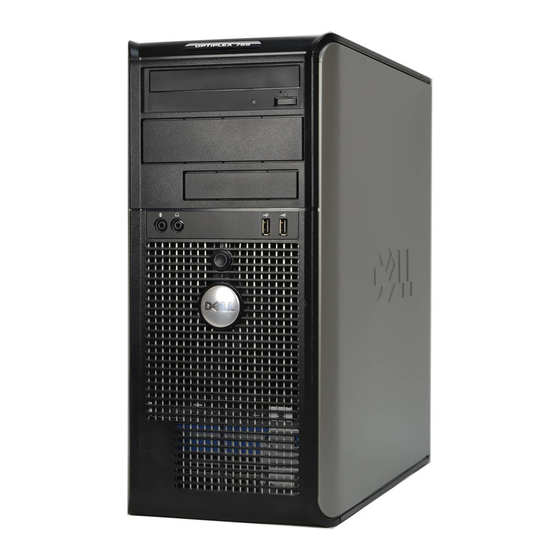
Mini Tower Computer About Your Mini Tower Computer Front View Mini Tower Computer... - Page 24 5.25-inch drive bay Can contain an optical drive. Insert a CD or DVD (if supported) into this drive. 5.25-inch drive bay Can contain an optical drive. Insert a CD or DVD (if supported) into this drive. 3.5-inch drive bay Can contain an optional floppy drive or optional media card reader. USB 2.0 connectors (2) Use the front USB connectors for devices that you connect occasionally, such as joysticks or cameras, or for bootable USB devices (see your online User’s Guide for...
-
Page 25: Back View
Back View cover-release latch This latch allows you to open the computer cover. padlock ring Insert a padlock to lock the computer cover. voltage selection switch Your computer is equipped with a manual voltage-selection switch. To help avoid damaging a computer with a manual voltage-selection switch, set the switch for the voltage that most closely matches the AC power available in your location. -
Page 26: Back Panel Connectors
power connector Insert the power cable. back panel connectors Plug serial, USB, and other devices into the appropriate connectors. See "Back Panel Connectors" on page 26. card slots (4) Access connectors for any installed PCI or PCI Express cards, PS/2 connector, eSATA connector, etc. -
Page 27: Removing The Computer Cover
network adapter To attach your computer to a network or broadband device, connect one end of a connector network cable to either a network jack or your network or broadband device. Connect the other end of the network cable to the network adapter connector on the back panel of your computer. - Page 28 4 Grip the sides of the computer cover and pivot the cover up using the hinge tabs as leverage points. 5 Remove the cover from the hinge tabs and set it aside on a soft nonabrasive surface. CAUTION: Graphics card heat sinks can become very hot during normal operation. Ensure that a graphics card heat sink has had sufficient time to cool before you touch it.
-
Page 29: Inside Your Computer
Inside Your Computer CAUTION: Before you begin any of the procedures in this section, follow the safety instructions located in the Product Information Guide CAUTION: To avoid electrical shock, always unplug your computer from the electrical outlet before removing the computer cover. NOTICE: Be careful when opening the computer cover to ensure that you do not accidentally disconnect cables from the system board. -
Page 30: Removing The Chassis Intrusion Switch
Removing the Chassis Intrusion Switch 1 Follow the procedures in "Before You Begin" on page 21. 2 Remove the computer cover (see "Removing the Computer Cover" on page 27). 3 Disconnect the chassis intrusion switch cable from the system board by using two fingers to squeeze the release mechanism on one side of the connector as you pull to disconnect the cable connector. -
Page 31: Resetting The Chassis Intrusion Detector
Resetting the Chassis Intrusion Detector 1 Turn on (or restart) your computer. 2 When the blue DELL™ logo appears, press <F2> immediately. If you wait too long and the operating system logo appears, continue to wait until you see the ®... -
Page 32: System Board Components
System Board Components speaker connector (INT_SPKR) RTC reset jumper (RTCRST) fan (FAN_CPU) intrusion switch connector (INTRUDER) processor connector (CPU) battery socket (BATTERY) processor power connector (12VPOWER) PCI Express x16 connector (SLOT1) memory module connectors (DIMM_1, PCI Express x1 connector (SLOT4) DIMM_2, DIMM_3, DIMM_4) Mini Tower Computer... - Page 33 password jumper (PSWD) PCI connector (SLOT2) SATA drive connectors (SATA0, SATA1, SATA2, PCI connector (SLOT3) SATA3) front-panel connector (FRONTPANEL) serial connector (SERIAL2) power connector (POWER) system board speaker (BEEP) external SATA connector (eSATA) aux power LED (aux_LED) internal USB (INT_USB) floppy connector (DSKT) Mini Tower Computer...
- Page 34 Mini Tower Computer...
-
Page 35: Mini Tower Computer Specifications
Mini Tower Computer Specifications Microprocessor Microprocessor type The following are supported: ® • Intel Core™2 • Intel vPro™ ® • Intel Celeron Internal cache L1: up to 128 KB; L2: up to 8 MB (depending on your processor) Memory Type 667-MHz or 800-MHz DDR2 SDRAM Memory connectors Memory modules supported... - Page 36 Video Type Intel Graphics Media Accelerator 3100 or DVI add-in card in PCI Express x16 slot or PCI Express x16 graphics card Audio Type ADI 1984 High Definition Audio Stereo conversion 24-bit analog-to-digital; 24-bit digital-to-analog Controllers Drives four SATA controllers and one eSATA controller supporting one device each Expansion Bus Bus type...
- Page 37 Drives Internally accessible • Two SATA (Serial ATA) hard drives • One3.5-inch floppy drive or media reader • Two SATA optical drives Externally accessible One eSATA drive (optional) Connectors External connectors: Serial 9-pin connector; 16550C-compatible Parallel 25-pin connector (bidirectional) Video 15-pin VGA connector Network adapter RJ45 connector...
- Page 38 Key Combinations <F12> or <Ctrl><Alt><F8> displays a boot device menu that allows the user to enter a device for a single boot (during start-up only) as well as options to run hard drive and system diagnostics <Ctrl><p> displays the Management Engine BIOS Extension settings screen that allows you to modify the settings Controls and Lights Power control...
- Page 39 Physical Height 41.4 cm (16.3 inches) Width 18.5 cm (7.3 inches) Depth 43.9 cm (17.3 inches) Weight 12.34 kg (27.2 lb) Environmental Temperature: Operating 10° to 35°C (50° to 95°F) Storage –40° to 65°C (–40° to 149°F) Relative humidity 20% to 80% (noncondensing) Maximum vibration: Operating 0.25 G at 3 to 200 Hz at 0.5 octave/min...
- Page 40 Mini Tower Specifications...
-
Page 41: Cards
The brackets keep dust and dirt out of your computer and maintains the airflow that cools your computer. Your Dell™ computer supports a PS/2 serial port adapter and provides the following connectors for PCI and PCI Express cards: •... - Page 42 If you are replacing a card, uninstall the driver for the existing card. See the documentation that came with the card for instructions. 1 Follow the procedures in "Before You Begin" on page 21. 2 Remove the computer cover (see "Removing the Computer Cover" on page 27). 3 Gently push the release tab on the card retention latch from the inside to pivot the latch open.
- Page 43 CAUTION: Some network adapters automatically start the computer when they are connected to a network. To guard against electrical shock, be sure to unplug your computer from its electrical outlet before installing any cards. 8 If you are installing the card into the x16 card connector, position the card so that the securing slot is aligned with the securing tab, and gently pull the securing tab.
- Page 44 card fully seated card not fully seated bracket within slot bracket caught outside of slot 10 Before you lower the card retention mechanism, ensure that: • The tops of all cards and filler brackets are flush with the alignment bar. •...
-
Page 45: Removing A Pci Or Pci Express Card
14 If you installed a sound card: Enter system setup, select Audio Controller, and change the setting to Off (see "System Setup" on page 280). Connect external audio devices to the sound card’s connectors. Do not connect external audio devices to the microphone, speaker/headphone, or line-in connectors on the back panel of the computer. - Page 46 card retention latch alignment guide card card-edge connector card connector release tab 4 If necessary, disconnect any cables connected to the card. 5 If you are removing the card permanently, install a filler bracket in the empty card-slot opening. NOTE: Installing filler brackets over empty card-slot openings is necessary to maintain FCC certification of the computer.
-
Page 47: Ps/2 Serial Port Adapter
9 If you removed a network-adapter card connector: Enter system setup, select Network Controller, and change the setting to On (see "System Setup" on page 280). Connect the network cable to the integrated network connector on the back panel of the computer. - Page 48 4 Remove the filler bracket (if applicable). NOTE: See the documentation that came with the PS/2 serial port adapter for information on configuring the adapter, making internal connections, or customizing it for your computer. 5 Align the PS/2 serial-port adapter bracket in the retention slot and press down firmly. Ensure that the adapter is fully seated in the slot.
-
Page 49: Removing A Ps/2 Serial Port Adapter
NOTE: See the documentation for the PS/2 serial port adapter for information about the cable connections. 8 Replace the computer cover (see "Replacing the Computer Cover" on page 317). Removing a PS/2 Serial Port Adapter 1 Follow the procedures in "Before You Begin" on page 21. 2 Remove the computer cover (see "Removing the Computer Cover"... - Page 50 card retention latch alignment guide 4 Disconnect the PS/2 serial adapter cable from the system board (see "System Board Components" on page 32). 5 If necessary, disconnect any external cables connected to the adapter. 6 Ease the PS/2 serial-port adapter bracket out of its retention slot. 7 If you are removing the adapter permanently, install a filler bracket in the empty card-slot opening.
-
Page 51: Installing Esata
Installing eSATA eSATA allows for full SATA data transfer rates (3 GB/sec) between a drive and the chipset, approximately six times the data throughput of USB. eSATA on your computer also supports hot-plugging. Hot-plugging allows for device detection without powering down your computer prior to connecting the device to your computer. When a device is connected, the operating system automatically recognizes the change. - Page 52 4 Plug the free end of the eSATA cable into the eSATA connector on the system board. 5 Replace the computer cover (see "Replacing the Computer Cover" on page 317). 6 Boot your computer and enter system setup (see "Entering System Setup" on page 280). Use the esata option to enable the esata drive.
-
Page 53: Drives
Drives Your computer supports: • Two SATA (Serial ATA) hard drives • One 3.5-inch floppy drive or media card reader • Two SATA optical drives • One eSATA drive (with optional bracket) 1 optical drive 2 3.5-inch drive or media card 3 hard drive reader General Drive Installation Guidelines... -
Page 54: Connecting Drive Cables
Connecting Drive Cables When you install a drive, you connect two cables—a DC power cable and a data interface cable—to the back of the drive. Data Interface Connectors SATA Connector data interface cable connector data interface connector Power Cable Connectors power cable power input connector Drives... -
Page 55: Connecting And Disconnecting Drive Cables
Connecting and Disconnecting Drive Cables When removing a cable with a pull-tab, grasp the colored pull-tab and pull until the connector detaches. When connecting and disconnecting a cable without a pull tab, hold the cable by the black connector at each end. - Page 56 data cable hard drive system board power cable connector 6 Press in on the blue release tabs on each side of the drive and slide the drive up and out of the computer. Drives...
-
Page 57: Installing A Hard Drive
hard drive release tabs (2) Installing a Hard Drive 1 Unpack the replacement hard drive, and prepare it for installation. 2 Check the documentation for the drive to verify that it is configured for your computer. 3 If your replacement hard drive does not have the plastic hard drive bracket attached, remove the bracket from the existing drive by unsnapping it from the drive. - Page 58 hard drive hard drive bracket 4 Snap the bracket onto the new drive. hard drive hard drive bracket pins Drives...
- Page 59 12 Exit system setup, and reboot the computer. 13 Partition and logically format your drive. See the documentation for your operating system for instructions. 14 Test the hard drive by running the Dell Diagnostics (see " on page 353). "Dell Diagnostics...
-
Page 60: Adding A Second Hard Drive
15 If the drive you just installed is the primary drive, install your operating system on the hard drive. If the drive you just installed is the primary drive, insert a bootable medium into your boot drive. See the documentation that came with the drive for instructions on installing any software required for drive operation. - Page 61 hard drive hard drive bracket pins 6 Carefully slide the new hard drive into the bay until it clicks into place. 7 Connect the power cable to the drive. Drives...
- Page 62 8 Locate an unused SATA connector on the system board and attach a data cable to this connector and to the second hard drive. Drives...
-
Page 63: Floppy Drive
11 Exit system setup, and reboot the computer. 12 Partition and logically format your drive. See the documentation for your operating system for instructions. 13 Test the hard drive by running the Dell Diagnostics (see " on page 353). "Dell Diagnostics 14 If the drive you just installed is the primary drive, install your operating system on the hard drive. -
Page 64: Removing The Floppy Drive
Removing the Floppy Drive 1 Boot your computer and enter system setup (see "Entering System Setup" on page 280). Use the Diskette Drive option to disable the floppy drive. 2 Follow the procedures in "Before You Begin" on page 21. 3 Remove the computer cover (see "Removing the Computer Cover"... - Page 65 3 Align the shoulder screws on the floppy drive with the shoulder screw slots, and gently slide it into the bay until it clicks into place. 1 floppy drive 2 shoulder screws (4) 3 shoulder screw slots (2) 4 Attach the power and data cables to the floppy drive and to the system board. Drives...
-
Page 66: Media Card Reader
6 Enter system setup (see "Entering System Setup" on page 280), and use the Diskette Drive option to enable your new floppy drive. 7 Verify that your computer works correctly by running the Dell Diagnostics (see "Dell Diagnostics" on page 353). -
Page 67: Installing The Media Card Reader
3 Remove the drive panel by sliding the drive release latch downward to open the panel, and then remove it from the hinges. 4 Disconnect the cable from the back of the media card reader. 1 media card reader 2 drive release latch 5 Grasp the sliding plate lever and slide it towards the bottom of the computer until the drive panel snaps open;... - Page 68 3 Align the shoulder screws on the media card reader with the shoulder screw slots, and gently slide it into the bay until it clicks into place. 1 media card 2 shoulder screws (4) 3 shoulder screw slots (2) reader 4 Attach the cable to the media card reader and to the system board.
-
Page 69: Optical Drive
5 Replace the computer cover (see "Replacing the Computer Cover" on page 317). 6 Verify that your computer works correctly by running the Dell Diagnostics (see "Dell Diagnostics" on page 353). Optical Drive CAUTION: Before you begin any of the procedures in this section, follow the safety instructions located in the... -
Page 70: Installing An Optical Drive
optical drive drive release latch Installing an Optical Drive 1 Follow the procedures in "Before You Begin" on page 21. 2 Remove the computer cover (see "Removing the Computer Cover" on page 27). 3 If you are replacing an optical drive, remove the shoulder screws from the existing drive and attach the screws to the replacement drive. - Page 71 5 Check the documentation that accompanied the drive to verify that the drive is configured for your computer. 6 Align the shoulder screws on the optical drive with the shoulder screw slots, and slide the drive into the bay until it clicks into place. 1 optical drive 2 shoulder screws (3) 3 shoulder screw slots (2)
- Page 72 10 Update your configuration information in system setup by setting the appropriate Drive option (SATA-1, SATA-2, or SATA-3) under Drives. See "System Setup" on page 280. 11 Verify that your computer works correctly by running the Dell Diagnostics (see "Dell Diagnostics" on page 353).
-
Page 73: Processor
Processor CAUTION: Before you begin any of the procedures in this section, follow the safety instructions located in the Product Information Guide NOTICE: To prevent static damage to components inside your computer, discharge static electricity from your body before you touch any of your computer’s electronic components. You can do so by touching an unpainted metal surface on the computer chassis. -
Page 74: Installing The Processor
NOTICE: Unless a new heat sink is required for the new processor, reuse the original heat sink assembly when you replace the processor. 5 Open the processor cover by sliding the release lever from under the center cover latch on the socket. Then, pull the lever back to release the processor. - Page 75 3 Unpack the new processor, being careful not to touch the underside of the processor. NOTE: You must position the processor correctly in the socket to avoid permanent damage to the processor and the computer when you turn on the computer. 4 If the release lever on the socket is not fully extended, move it to that position.
- Page 76 9 Pivot the socket release lever back toward the socket, and snap it into place to secure the processor. 10 Clean the thermal grease from the bottom of the heat sink. NOTICE: Ensure that you apply new thermal grease. New thermal grease is critical for ensuring adequate thermal bonding, which is a requirement for optimal processor operation.
-
Page 77: I/O Panel
I/O Panel Removing the I/O Panel CAUTION: Before you begin any of the procedures in this section, follow the safety instructions located in the Product Information Guide CAUTION: To guard against electrical shock, always unplug your computer from the electrical outlet before removing the cover. -
Page 78: Replacing The I/O Panel
1 I/O panel release button 2 securing screw 3 I/O panel 4 I/O cable connector Replacing the I/O Panel 1 To replace the I/O panel, follow the removal procedure in the reverse order. NOTE: Use the guides on the I/O panel bracket to help position the I/O panel in place, and use the notch on the I/O panel bracket to help seat the panel. -
Page 79: Power Supply
Power Supply Replacing the Power Supply CAUTION: Before you begin any of the procedures in this section, follow the safety instructions located in the Product Information Guide NOTICE: To prevent static damage to components inside your computer, discharge static electricity from your body before you touch any of your computer’s electronic components. - Page 80 1 release button 2 power supply 3 screws (4) 4 AC power connector 6 Slide the power supply toward the front of the computer by approximately 1 inch. 7 Lift the power supply up and out of the computer. 8 Slide the replacement power supply into place. 9 Replace the screws that secure the power supply to the back of the computer chassis.
-
Page 81: Dc Power Connectors
DC Power Connectors DC Power Connector P1 13 14 15 16 17 18 19 20 21 22 23 24 Pin Number Signal name 18-AWG Wire +3.3 VDC Orange 9 10 11 12 +3.3 VDC Orange Black Power Supply... - Page 82 Pin Number Signal name 18-AWG Wire +5 VDC Black +5 VDC Black PS_PWRGOOD Gray P5AUX Purple V_12P0_DIG White V_12P0_DIG White +3.3 VDC Orange +3.3VDC/SE* Orange -12 VDC Blue Black PWR_PS_ON Green Black Black Black +5 VDC +5 VDC Power Supply...
-
Page 83: Dc Power Connector P2
Pin Number Signal name 18-AWG Wire +5 VDC Black *Optional wire. Use 22-AWG wire instead of 18-AWG wire. DC Power Connector P2 Pin Number Signal Name 18-AWG Wire Black Black +12 VADC Yellow +12 VADC Yellow DC Power Connectors P3, P5, P8, and P9 Pin Number Signal name 18-AWG Wire... -
Page 84: Dc Power Connector P7
DC Power Connector P7 Pin Number Signal Name 22-AWG Wire +5 VDC Black Black +12 VDC Yellow DC Power Connector P10 Pin Number Signal name 18-AWG Wire +12 VBDC White Black Black +5 VDC Power Supply... -
Page 85: Speakers
Speakers Installing a Speaker CAUTION: Before you begin any of the procedures in this section, follow the safety instructions located in the Product Information Guide. NOTICE: To prevent static damage to components inside your computer, discharge static electricity from your body before you touch any of your computer’s electronic components. -
Page 86: Removing A Speaker
Removing a Speaker CAUTION: Before you begin any of the procedures in this section, follow the safety instructions located in the Product Information Guide. NOTICE: To prevent static damage to components inside your computer, discharge static electricity from your body before you touch any of your computer’s electronic components. You can do so by touching an unpainted metal surface on the computer chassis. -
Page 87: Desktop Computer
If your operating system has ACPI enabled, when you press the power button the computer will perform an operating system shutdown. Dell badge This badge can be rotated to match the orientation of your computer. To rotate, place fingers around the outside of the badge, press firmly, and turn the badge. You can also rotate the badge using the slot provided near the bottom of the badge. -
Page 88: Back View
power light The power light illuminates and blinks or remains solid to indicate different operating states: • No light — The computer is turned off. • Steady green — The computer is in a normal operating state. • Blinking green — The computer is in a power-saving mode. •... -
Page 89: Back Panel Connectors
voltage selection switch Your computer is equipped with a manual voltage selection switch. To help avoid damaging a computer with a manual voltage selection switch, set the switch for the voltage that most closely matches the AC power available in your location. NOTICE: In Japan, the voltage selection switch must be set to the 115-V position. -
Page 90: Removing The Computer Cover
network adapter To attach your computer to a network or broadband device, connect one end of a connector network cable to either a network jack or your network or broadband device. Connect the other end of the network cable to the network adapter connector on the back panel of your computer. -
Page 91: Inside Your Computer
4 Grip the sides of the computer cover and pivot the cover up using the hinge tabs as leverage points. 5 Remove the cover from the hinge tabs and set it aside on a soft nonabrasive surface. CAUTION: Graphics card heat sinks can become very hot during normal operation. Ensure that a graphics card heat sink has had sufficient time to cool before you touch it. -
Page 92: Chassis Intrusion Switch
NOTICE: Be careful when opening the computer cover to ensure that you do not accidentally disconnect cables from the system board. drive bays (media card card slots reader or floppy drive, optical drive and hard drive) power supply heat sink assembly optional chassis-intrusion front I/O panel switch... -
Page 93: Replacing The Chassis Intrusion Switch
Resetting the Chassis Intrusion Detector 1 Turn on (or restart) your computer. 2 When the blue DELL™ logo appears, press <F2> immediately. If you wait too long and the operating system logo appears, continue to wait until you see the ®... -
Page 94: Removing The Heat Sink Assembly
3 Select the Chassis Intrusion option and then press the left- or right-arrow key to select Reset. Change the setting to On, On-Silent, or Disabled. NOTE: The default setting is On-Silent. 4 Save your BIOS settings and exit system setup. Removing the Heat Sink Assembly 1 Loosen the captive screw on each side of the heat sink assembly. -
Page 95: System Board Components
System Board Components Desktop Computer... - Page 96 internal speaker (INT_SPKR) intrusion switch connector (INTRUDER) processor connector (CPU) battery socket (BATTERY) processor power connector (12VPOWER) PCI Express x16 connector (SLOT1) memory module connectors (DIMM_1, PCI connector (SLOT2) DIMM_2, DIMM_3, DIMM_4) password jumper (PSWD) PCI connector (SLOT3) SATA connectors (SATA0, SATA1, SATA2) riser connector (uses PCI-E port/SLOT1 and PCI port/SLOT2) front-panel connector (FRONTPANEL)
-
Page 97: Desktop Computer Specifications
Desktop Computer Specifications Microprocessor Microprocessor type The following are supported: ® • Intel Core™2 • Intel vPro™ ® • Intel Celeron Internal cache L1: up to 128 KB; L2: up to 8 MB (depending on your processor) Memory Type 667-MHz or 800-MHz DDR2 SDRAM Memory connectors Memory modules supported 512 MB, 1 GB, or 2 GB non-ECC... - Page 98 Video Type • Intel Graphics Media Accelerator 3100 (integrated on system board) • PCI Express x16 slot can support either a PCI Express graphics card or a DVI graphics card (for dual-monitor support) Audio Type ADI 1984 High Definition Audio Stereo conversion 24-bit analog-to-digital;...
- Page 99 Expansion Bus connector size 164 pins (x16) connector data width 16 PCI Express lanes (x16) (maximum) PCI and PCI Express: with optional, full-height PCI Express riser-card cage, supporting both low-profile and full-height cards connectors card size one low-profile card and one full-height card connector size 120 pins connector data width...
- Page 100 Drives Externally accessible one One eSATA drive (optional) Internally accessible • two SATA (Serial ATA) hard drives • one3.5-inch floppy drive or media card reader • one SATA optical drive Connectors External connectors: Serial 9-pin connector; 16550C-compatible Parallel 25-pin connector (bidirectional) Video 15-pin VGA connector Network adapter...
- Page 101 Key Combinations ® ® <Ctrl><Alt><Del> in Microsoft Windows XP , brings up the Windows Security ® window; in MS-DOS mode, restarts (reboots) the computer <F2> or <Ctrl><Alt><Enter> starts embedded system setup (during system start-up only) <F3> automatically starts the computer from the network environment specified by the remote boot environment (PXE) rather than from one of the devices in the system setup Boot Sequence option (during system start-up only)
- Page 102 (continued) Power Heat dissipation 955 BTU/hr NOTE: Heat dissipation is calculated based upon the power supply rating. Voltage manual selection power supplies — 90 to 135 V at 50/60 Hz; 180 to 265 V at 50/60 Hz Backup battery 3-V CR2032 lithium coin cell Physical Height 11.4 cm (4.5 inches)
-
Page 103: Cards
The brackets keep dust and dirt out of your computer and maintains the airflow that cools your computer. Your Dell™ computer supports a PS/2 serial port adapter and provides the following connectors on the system board for PCI and PCI Express cards: •... - Page 104 card card insert card-retention latch release tab system board connector 4 If you are installing a card in an empty card connector on the system board, remove the filler bracket to create a card-slot opening at the back of the computer. Then continue with step 6. 5 If you are installing a card to replace one already installed in the computer, remove the installed card (see "Removing a PCI Card"...
- Page 105 release tab on card- retention latch card card-edge connector card connector CAUTION: Some network adapters automatically start the computer when they are connected to a network. To guard against electrical shock, be sure to unplug your computer from its electrical outlet before installing any cards.
- Page 106 PCI Express x16 card release lever securing slot (not all cards) securing tab PCI Express x16 card connector 8 Place the card in the connector and press down firmly. Using the following illustration as a guide, ensure that the card is fully seated in the slot. Expansion Cards...
- Page 107 card fully seated card not fully seated bracket within slot bracket caught outside of slot NOTE: If you are installing a PCI Express x16 card, ensure that the securing tab on the connector’s release lever fits into the notch on the front end of the card. 9 Gently rotate the release tab downward to move the card-retention latch into place to secure the cards.
- Page 108 release tab card-edge connector card-retention latch card connector card NOTICE: Do not route card cables over or behind the cards. Cables routed over the cards can prevent the computer cover from closing properly or cause damage to the equipment. 10 Connect any cables that should be attached to the card. 11 Replace the computer cover (see "Replacing the Computer Cover"...
-
Page 109: Removing A Pci Card
Connect the network cable to the connector on the network adapter card. Do not connect the network cable to the integrated network connector on the back panel of the computer. 14 Install any drivers required for the card as described in the card documentation. Removing a PCI Card 1 Follow the procedures in "Before You Begin"... - Page 110 PCI Express x16 card release lever securing slot (not all cards) securing tab PCI Express x16 card connector 6 Grasp the card by its top corners, and ease it out of its connector. 7 If you are removing the card permanently, install a filler bracket in the empty card-slot opening. NOTE: Installing filler brackets over empty card-slot openings is necessary to maintain FCC certification of the computer.
-
Page 111: Installing A Pci Card In The Riser-Card Cage
12 If you removed a network adapter card: Enter system setup, select Network Controller, and change the setting to On (see "Entering System Setup" on page 280). Connect the network cable to the integrated network connector on the back panel of the computer. - Page 112 5 If you are installing a new card, remove the filler bracket to create an empty card-slot opening. If you are replacing a card that is already installed in the computer, remove the card. If necessary, disconnect any cables connected to the card. Grasp the card by its corners, and ease it out of its connector.
- Page 113 8 Insert the card firmly into the card connector on the riser-card cage. 9 Lower the card-retention latch and press it into place, securing the card(s) in the computer. 10 Replace the riser-card cage: Align the tabs in the side of the riser-card cage with the slots on the side of the computer, and slide the riser-card cage down into place.
-
Page 114: Removing A Pci Card From The Riser-Card Cage
15 If you installed a network adapter card and want to turn off the integrated network adapter: Enter system setup, select Network Controller and change the setting to Off (see "Entering System Setup" on page 280). Connect the network cable to the network adapter card’s connectors. Do not connect the network cable to the integrated network connector on the back panel of the computer. - Page 115 5 If necessary, disconnect any cables connected to the card. 6 Grasp the card by its top corners, and ease it out of its connector. 7 If you are removing the card permanently, install a filler bracket in the empty card-slot opening. NOTE: Installing filler brackets over empty card-slot openings is necessary to maintain FCC certification of the computer.
-
Page 116: Ps/2 Serial Port Adapter
12 If you removed a sound card: Enter system setup, select Audio Controller, and change the setting to On (see "Entering System Setup" on page 280). Connect external audio devices to the audio connectors on the computer back panel. 13 If you removed a network adapter card: Enter system setup, select Network Controller, and change the setting to On (see "Entering System Setup"... - Page 117 5 Align the PS/2 serial-port adapter bracket in the retention slot and press down firmly. Ensure that the adapter is fully seated in the slot. 6 Before you close the card retention mechanism, ensure that: • The tops of all cards and filler brackets are flush with the alignment bar. •...
-
Page 118: Removing A Ps/2 Serial Port Adapter
release tab adapter retention latch PS/2 serial-port adapter bracket serial port adapter connector serial port adapter system board connector (SERIAL2) 8 Connect the adapter cable to the PS/2 serial port adapter connector (SERIAL2) on the system board (see "System Board Components" on page 95). NOTE: See the documentation for the PS/2 serial port adapter for information about the cable connections. -
Page 119: Installing A Ps/2 Serial Port Adapter In The Riser-Card Cage
4 Disconnect the PS/2 serial-port cable from the system board (see "System Board Components" on page 95). 5 Ease the PS/2 serial-port adapter bracket out of its retention slot. 6 If you are removing the adapter permanently, install a filler bracket in the empty card-slot opening. NOTE: Installing filler brackets over empty card-slot openings is necessary to maintain FCC certification of the computer. - Page 120 Rotate the riser-card cage handle up and gently pull on the handle to lift the riser-card cage up and away from the computer. riser-card cage handle riser cards (2) 4 Gently lift the release tab on the card retention latch from the inside to pivot the latch open. Pivot the latch until it snaps into the open position.
-
Page 121: Removing A Ps/2 Serial Port Adapter From The Riser-Card Cage
10 Secure the card(s) by closing the card retention latch and snapping it into place. NOTICE: Do not route card cables over the cards. Cables routed over the cards can prevent the computer cover from closing properly or cause damage to the equipment. 11 Connect the adapter cable to the PS/2 serial port adapter connector (PS2/SERIAL2) on the system board (see "System Board Components"... - Page 122 riser-card cage handle riser cards (2) 4 Gently lift the release tab on the card retention latch from the inside to pivot the latch open. Pivot the latch until it snaps into the open position. 5 Disconnect the PS/2 serial-port cable from the system board (see "System Board Components" on page 95).
-
Page 123: Esata
11 Replace the computer cover (see "Replacing the Computer Cover" on page 317). 12 Uninstall the adapter’s driver. See the documentation that came with the adapter for instructions. eSATA eSATA allows for full SATA data transfer rates (3 GB/sec) between a drive and the chipset, approximately six times the data throughput of USB. -
Page 124: Installing Esata With A Riser
5 Replace the computer cover (see "Replacing the Computer Cover" on page 317). 6 Boot your computer and enter system setup (see "Entering System Setup" on page 280). Use the esata option to enable the eSATA drive. Installing eSATA With a Riser 1 Remove the computer cover (see "Removing the Computer Cover"... - Page 125 4 Insert the bracket for the eSATA connector into that opening and press down on the release tab to hold the bracket in place. 5 Plug the free end of the eSATA cable into the eSATA connector on the system board. Expansion Cards...
- Page 126 6 Replace the riser. riser-card cage riser cards (2) slots system board connectors (2) 7 Replace the computer cover (see "Replacing the Computer Cover" on page 317). 8 Boot your computer and enter system setup (see "Entering System Setup" on page 280). Use the esata option to enable the eSATA drive.
-
Page 127: Drives
If you will be operating your computer without an optical drive or a 3.5-inch device (floppy drive or media card reader) installed, the appropriate drive bay insert must be installed in place of the drive. Contact Dell if you need a drive bay insert. -
Page 128: Connecting Drive Cables
connected to. For example, if you have two SATA hard drives and one SATA optical drive, connect the two hard drives to the SATA0 and SATA1 connectors, and connect the SATA optical drive to the SATA2 connector. (See "System Board Components" on page 95 for the location of the SATA connectors on the system board.) Connecting Drive Cables When you install a drive, you connect two cables—a DC power cable and a data interface cable—to the... -
Page 129: Connecting And Disconnecting Drive Cables
Connecting and Disconnecting Drive Cables When removing a cable with a pull-tab, grasp the colored pull-tab and pull until the connector detaches. When connecting and disconnecting a cable without a pull tab, hold the cable by the black connector at each end. - Page 130 metal insert 5 Press the release tabs on the plastic insert and press from behind to remove. shoulder screws plastic drive insert Drives...
-
Page 131: Replacing Drive Inserts
If you will be operating your computer without an optical drive or a 3.5-inch device (floppy drive or media card reader) installed, the appropriate drive bay insert must be installed in place of the drive. Contact Dell if you need a drive bay insert. See "Removing Drive Inserts" on page 129. -
Page 132: Installing An Optical Drive
5 If you are not replacing the optical drive at this time, install the optical drive insert by lowering it into the drive bay until it clicks into place. Contact Dell if you need a drive bay insert. Installing an Optical Drive 1 Unpack the drive and prepare it for installation. - Page 133 4 If you are replacing an existing drive: Follow procedures in "Removing an Optical Drive" on page 131 to remove the existing drive. Remove the three shoulder screws from the existing drive. Insert the three shoulder screws into the sides of the new drive and tighten them. 5 Connect the power and data cables to the drive.
-
Page 134: Floppy Drive
If you will be operating your computer without an optical drive or a 3.5-inch device (floppy drive) installed, the appropriate drive bay insert must be installed in place of the drive. Contact Dell if you need a drive bay insert. -
Page 135: Removing A Floppy Drive
5 Disconnect the power and data cables from the back of the floppy drive. 6 If you are not replacing the floppy drive or media card reader at this time, install the floppy drive inserts (see "Replacing Drive Inserts" on page 131). Contact Dell if you need a drive bay insert. Drives... -
Page 136: Installing A Floppy Drive
Installing a Floppy Drive 1 If you are installing a new floppy drive Remove the drive inserts (see "Removing Drive Inserts" on page 129). Pull to remove the floppy drive insert that should be installed in the drive bay. Remove the four shoulder screws from the drive panel insert. drive insert 2 If you are replacing an existing floppy drive: Remove the four shoulder screws from the existing drive or media card reader. -
Page 137: Media Card Reader
9 Enter system setup and set the Diskette Drive option to enable your new floppy drive (see "System Setup" on page 280). 10 Verify that your computer works correctly by running the Dell Diagnostics (see "Dell Diagnostics" on page 353). -
Page 138: Removing A Media Card Reader
If you will be operating your computer without an optical drive or a 3.5-inch drive installed, the appropriate drive bay insert must be installed in place of the drive. Contact Dell if you need a drive bay insert. Removing a Media Card Reader 1 Follow the procedures in "Before You Begin"... -
Page 139: Installing A Media Card Reader
6 If you are not replacing the media card reader at this time, install the 3.5 inch drive insert (see "Replacing Drive Inserts" on page 131). Contact Dell if you need a drive bay insert. Installing a Media Card Reader 1 If you are installing a new drive or media card reader: Remove the drive inserts (see "Removing Drive Inserts"... - Page 140 drive insert 2 If you are replacing an existing media card reader: Remove the four shoulder screws from the existing media card reader. 3 Insert the four shoulder screws into the sides of the new media card reader and tighten them. 4 Attach the cable to the media card reader and system board connector.
- Page 141 5 Align the shoulder screws with the screw guides, and slide the media card reader into the bay until it clicks into place. power cable slot verification number Drives...
-
Page 142: Hard Drive
7 Check all cable connections, and fold cables out of the way to provide airflow for the fan and cooling vents. 8 Replace the computer cover (see "Replacing the Computer Cover" on page 317). 9 Verify that your computer works correctly by running the Dell Diagnostics (see "Dell Diagnostics" on page 353). Hard Drive... -
Page 143: Installing A Hard Drive
securing clips (2) hard drive Installing a Hard Drive 1 Check the documentation for the drive to verify that it is configured for your computer. NOTICE: To avoid damage to the drive, do not set it on a hard surface. Instead, set the drive on a surface, such as a foam pad, that will sufficiently cushion it. - Page 144 hard drive release tabs (2) plastic hard drive bracket 4 Attach the bracket to the new drive by snapping it onto the drive. securing tabs (2) release tabs (2) drive plastic hard drive bracket 5 Connect the power and data cables to the drive. 6 Locate the correct slot for the drive, and slide the drive into the bay until it clicks into place.
- Page 145 14 Partition and logically format your drive. NOTE: For instructions, see the documentation that came with your operating system. 15 Test the hard drive by running the Dell Diagnostics (see "Dell Diagnostics" on page 353). 16 Install your operating system on the hard drive. NOTE: For instructions, see the documentation that came with your operating system.
-
Page 146: Replacing A Second Hard Drive
Replacing a Second Hard Drive For information on RAID configuration, see "About RAID Configurations" on page 295. CAUTION: Product Before you begin any of the procedures in this section, follow the safety instructions in the Information Guide CAUTION: To guard against electrical shock, always unplug your computer from the electrical outlet before removing the computer cover. - Page 147 10 Locate an unused SATA connector on the system board and attach a data cable from the second hard drive to the SATA connector. NOTICE: Always connect the data cable to the SATA1 connector when installing a second hard drive. Drives...
- Page 148 16 Partition and logically format your drive. NOTE: For instructions, see the documentation that came with your operating system. 17 Test the hard drive by running the Dell Diagnostics (see "Dell Diagnostics" on page 353). 18 Install your operating system on the hard drive. NOTE: For instructions, see the documentation that came with your operating system.
-
Page 149: Processor
Processor CAUTION: Before you begin any of the procedures in this section, follow the safety instructions located in the Product Information Guide NOTICE: To prevent static damage to components inside your computer, discharge static electricity from your body before you touch any of your computer’s electronic components. You can do so by touching an unpainted metal surface on the computer chassis. -
Page 150: Installing The Processor
NOTICE: When replacing the processor, do not touch any of the pins inside the socket or allow any objects to fall on the pins in the socket. 5 Gently remove the processor from the socket. Leave the release lever extended in the release position so that the socket is ready for the new processor. - Page 151 processor cover release lever front alignment-notch processor socket and processor pin-1 indicator processor socket rear alignment-notch center cover latch NOTICE: To avoid damage, ensure that the processor aligns properly with the socket, and do not use excessive force when you install the processor. 7 Set the processor lightly in the socket and ensure that the processor is positioned correctly.
- Page 152 12 Install the heat sink assembly: Place the heat sink assembly back onto the heat-sink assembly bracket. Rotate the heat sink assembly down towards the computer base and tighten the two captive screws. NOTICE: Ensure that the heat sink assembly is correctly seated and secure. heat sink assembly heat-sink assembly bracket captive screw housing (2)
-
Page 153: I/O Panel
I/O Panel Removing the I/O Panel CAUTION: Before you begin any of the procedures in this section, follow the safety instructions located in the Product Information Guide CAUTION: To guard against electrical shock, always unplug your computer from the electrical outlet before removing the cover. -
Page 154: Replacing The I/O Panel
1 securing screw 2 I/O panel 3 I/O cable connector 4 I/O connector pull loop Replacing the I/O Panel To replace the I/O panel, follow the removal procedures in the reverse order. NOTE: Use the guides on the I/O panel bracket to help position the I/O panel in place and use the notch on the I/O panel bracket to help seat the card. -
Page 155: Power Supply
Power Supply Replacing the Power Supply CAUTION: Before you begin any of the procedures in this section, follow the safety instructions located in the Product Information Guide. NOTICE: To prevent static damage to components inside your computer, discharge static electricity from your body before you touch any of your computer’s electronic components. - Page 156 1 release button 2 power supply 3 screws (2) 4 AC power connector 7 Slide the power supply toward the front of the computer approximately one inch. 8 Lift the power supply up and out of the computer. 9 Slide the replacement power supply into place. 10 Replace the screws that secure the power supply to the back of the computer chassis.
-
Page 157: Dc Power Connectors
DC Power Connectors DC Power Connector P1 13 14 15 16 17 18 19 20 21 22 23 24 Signal name 18-AWG Number Wire +3.3 VDC Orange 9 10 11 12 +3.3 VDC Orange Black +5 VDC Black Power Supply... - Page 158 Signal name 18-AWG Number Wire +5 VDC Black PS_PWRGOOD* Gray P5AUX Purple +12 VDC White +12 VDC White +3.3 VDC Orange +3.3 VDC/SE Orange +12 VDC* Blue Black PWR_PS_ON* Green Black Black Black +5 VDC +5 VDC Power Supply...
-
Page 159: Dc Power Connector P2
Signal name 18-AWG Number Wire +5 VDC Black *Use 22-AWG wire instead of 18-AWG wire. DC Power Connector P2 Pin Number Signal Name 18-AWG Wire Black Black +12 VDC Yellow +12 VDC Yellow Power Supply... -
Page 160: Dc Power Connector P3
DC Power Connector P3 Pin Number Signal name 18-AWG Wire +12VDC Yellow Black Black +5 VDC DC Power Connector P4 Pin Number Signal Name 22-AWG Wire +5 VDC Black Black +12 VDC Yellow DC Power Connector P5 and P6 Pin Number Signal name 18-AWG Wire +3.3 VDC... - Page 161 Pin Number Signal name 18-AWG Wire Black +12 VDC Yellow Power Supply...
- Page 162 Power Supply...
-
Page 163: Speakers
Speakers Installing a Speaker CAUTION: Before you begin any of the procedures in this section, follow the safety instructions located in the Product Information Guide. NOTICE: To prevent static damage to components inside your computer, discharge static electricity from your body before you touch any of your computer’s electronic components. -
Page 164: Removing A Speaker
Removing a Speaker CAUTION: Before you begin any of the procedures in this section, follow the safety instructions located in the Product Information Guide. NOTICE: To prevent static damage to components inside your computer, discharge static electricity from your body before you touch any of your computer’s electronic components. You can do so by touching an unpainted metal surface on the computer chassis. -
Page 165: Small Form Factor Computer
If your operating system has ACPI enabled, when you press the power button the computer will perform an operating system shutdown. Dell badge Can be rotated to match the orientation of your computer. To rotate, place fingers around the outside of the badge, press firmly, and turn the badge. You can also rotate the badge using the slot provided near the bottom of the badge. -
Page 166: Back View
"Power Management for Windows XP and Windows Vista" on page 292. See "Dell Diagnostics" on page 353 for a description of light codes that can help you troubleshoot problems with your computer. -
Page 167: Back Panel Connectors
voltage selection switch Your computer is equipped with a manual voltage-selection switch. To help avoid damaging a computer with a manual voltage selection switch, set the switch for the voltage that most closely matches the AC power available in your location. NOTICE: In Japan, the voltage selection switch must be set to the 115-V position. -
Page 168: Removing The Computer Cover
network adapter To attach your computer to a network or broadband device, connect one end of a connector network cable to either a network jack or your network or broadband device. Connect the other end of the network cable to the network adapter connector on the back panel of your computer. -
Page 169: Inside Your Computer
4 Grip the sides of the computer cover and pivot the cover up using the bottom hinges as leverage points. 5 Remove the cover from the hinge tabs and set it aside on a soft nonabrasive surface. CAUTION: Graphics card heat sinks can become very hot during normal operation. Ensure that a graphics card heat sink has had sufficient time to cool before you touch it. -
Page 170: Chassis Intrusion Switch
NOTICE: Be careful when opening the computer cover to ensure that you do not accidentally disconnect cables from the system board. drive-release latch hard drive optical drive system board power supply and fan heat sink assembly Chassis Intrusion Switch CAUTION: Before you begin any of the procedures in this section, follow the safety instructions located in the Product Information Guide NOTE:... -
Page 171: Replacing The Chassis Intrusion Switch
Resetting the Chassis Intrusion Detector 1 Turn on (or restart) your computer. 2 When the blue DELL™ logo appears, press <F2> immediately. If you wait too long and the operating system logo appears, continue to wait until you see the ®... -
Page 172: System Board Components
3 Select the Chassis Intrusion option and then press the left- or right-arrow key to select Reset. Change the setting to On, On-Silent, or Disabled. NOTE: The default setting is On-Silent. 4 Save your BIOS settings and exit system setup. System Board Components Small Form Factor Computer... - Page 173 internal speaker connector (INT_SPKR) RTC reset jumper (RTCRST) processor connector (CPU) intrusion switch connector (INTRUDER) processor power connector (12VPOWER) battery socket (BATTERY) memory module connectors (DIMM_1, PCI Express x16 connector (SLOT1) DIMM_2, DIMM_3, DIMM_4) password jumper (PSWD) PCI connector (SLOT2) SATA connectors (SATA0, SATA1) serial connector (SERIAL2) front-panel connector (FRONTPANEL)
- Page 174 Small Form Factor Computer...
-
Page 175: Small Form Factor Computer Specifications
Small Form Factor Computer Specifications Microprocessor Microprocessor type The following are supported: ® • Intel Core™2 • Intel vPro™ ® • Intel Celeron Internal cache L1: up to 128 KB; L2: up to 8 MB (depending on your processor) Memory Type 667-MHz or 800-MHz DDR2 SDRAM Memory connectors... - Page 176 Video Type • Intel Graphics Media Accelerator 3100 (integrated on system board) • PCI Express x16 slot can support either a PCI Express graphics card or a DVI graphics card (for dual-monitor support) Audio Type ADI 1984 High Definition Audio Stereo conversion 24-bit analog-to-digital;...
- Page 177 Drives Externally accessible one bay for a slimline floppy drive; one bay for a slimline optical drive Internally accessible one bay for a 1-inch-high hard drive Connectors External connectors: Serial 9-pin connector; 16550C-compatible Parallel 25-pin connector (bidirectional) Optional PS/2 with secondary serial two 6-pin mini-DINs port adapter NOTE:...
- Page 178 1000-Mb (1-Gb) operation Activity light (on integrated network yellow blinking light adapter) Diagnostic lights four lights on the front panel (See "Dell Diagnostics" on page 353.) Standby power light AUX_PWR on the system board Power NOTE:...
- Page 179 (continued) Power Heat dissipation 938 BTU/hr NOTE: Heat dissipation is calculated based upon the power supply rating. Voltage manual selection power supplies — 90 to 135 V at 50/60 Hz; 180 to 265 V at 50/60 Hz Backup battery 3-V CR2032 lithium coin cell Physical Height 9.26 cm (3.65 inches)
- Page 180 Small Form Factor Computer Specifications...
-
Page 181: Cards
The brackets keep dust and dirt out of your computer and maintains the airflow that cools your computer. Your Dell™ computer supports a PS/2 serial port adapter and provides the following connectors for PCI and PCI Express cards: •... - Page 182 release tab card retention latch card card-edge connector card connector 4 If you are installing a new card, remove the filler bracket to create a card-slot opening. Then continue with step 6. 5 If you are replacing a card that is already installed in the computer, remove the card. If necessary, disconnect any cables connected to the card.
- Page 183 card fully seated card not fully seated bracket within slot bracket caught outside of slot 8 Before closing the card retention latch, ensure that: • The tops of all cards and filler brackets are flush with the alignment guide • The notch in the top of the card or filler bracket fits around the alignment guide 9 Secure the card(s) by closing the card retention latch and snapping it into place.
-
Page 184: Removing A Pci Card
13 If you installed a network adapter card and want to turn off the integrated network adapter: Enter system setup, select Integrated NIC from the Onboard Devices group, and change the setting to Off (see "System Setup" on page 280). Connect the network cable to the network adapter card’s connectors. -
Page 185: Pci Express And Dvi Cards
6 If you are removing the card permanently, install a filler bracket in the empty card-slot opening. NOTE: Installing filler brackets over empty card-slot openings is necessary to maintain FCC certification of the computer. The brackets keep dust and dirt out of your computer and maintain the airflow that cools your computer. -
Page 186: Installing A Pci Express X16 Card Or Dvi Card
Installing a PCI Express x16 Card or DVI Card 1 Follow the procedures in "Before You Begin" on page 21. 2 Remove the computer cover (see "Removing the Computer Cover" on page 168). NOTE: For PCI card locations, see "System Board Components" on page 172. 3 Gently lift the release tab on the card retention latch from the inside and pivot the latch open. - Page 187 PCI Express x16 DVI-card DVI card connector PCI Express x16 card connector Expansion Cards...
- Page 188 card fully seated card not fully seated bracket within slot bracket caught outside of slot NOTICE: Do not route card cables over the cards. Cables routed over the cards can prevent the computer cover from closing properly or cause damage to the equipment. 8 Connect any cables that should be attached to the card.
-
Page 189: Removing A Pci Express X16 Card Or Dvi Card
13 If you installed a network adapter card and want to turn off the integrated network adapter: Enter system setup, select Integrated NIC from the Onboard Devices group, and change the setting to Off (see "System Setup" on page 280). Connect the network cable to the network adapter card’s connectors. - Page 190 7 While pressing the lever, pull the removal pull tab up and remove the card out of the card connector. PCI Express x16 DVI-card removal pull tab DVI card connector lever securing slot securing tab PCI Express x16 card connector 8 If you are removing the card permanently, install a filler bracket in the empty card-slot opening.
-
Page 191: Ps/2 Serial Port Adapter
13 If you removed a sound card: Enter system setup, select Integrated Audio from the Onboard Devices group, and change the setting to On (see "System Setup" on page 280). Connect external audio devices to the audio connectors on the back panel of the computer. NOTICE: To connect a network cable, first plug the cable into the network wall jack and then plug it into the computer. -
Page 192: Removing A Ps/2 Serial Port Adapter
release tab adapter retention latch serial port adapter bracket serial port adapter connector serial port adapter system board connector (PS2/SERIAL2) 8 Connect the adapter cable to the PS/2 serial port adapter connector (PS2/SERIAL2) on the system board (see "System Board Components" on page 172). NOTE: See the documentation for the PS/2 serial port adapter for information about the cable connections. -
Page 193: Esata
5 Ease the PS/2 serial-port adapter bracket out of its retention slot. 6 If you are removing the adapter permanently, install a filler bracket in the empty card-slot opening. NOTE: Installing filler brackets over empty card-slot openings is necessary to maintain FCC certification of the computer. - Page 194 4 Plug the free end of the eSATA cable into the eSATA connector on the system board (see "System Board Components" on page 172). 5 Replace the computer cover (see "Replacing the Computer Cover" on page 317). 6 Boot your computer and enter system setup (see "Entering System Setup" on page 280). Use the esata option to enable the eSATA drive.
-
Page 195: Drives
Drives Your computer supports: • One SATA (serial ATA) hard drive • One slimline floppy drive or media card reader • One SATA slimline optical drive • One eSATA drive 3.5-inch drive bay for optional floppy drive or media card reader slimline optical drive hard drive... -
Page 196: Connecting Drive Cables
Connecting Drive Cables When you install a drive, you connect two cables (a DC power cable and a data interface cable) to the back of the drive. Data Interface Connectors Serial ATA (SATA) Connector data interface cable connector data interface connector Power Cable Connectors power cable power input connector... -
Page 197: Hard Drive
When connecting and disconnecting a SATA data cable, hold the cable by the black connector at each end. Hard Drive CAUTION: Product Before you begin any of the procedures in this section, follow the safety instructions in the Information Guide CAUTION: To guard against electrical shock, always unplug your computer from the electrical outlet before removing the computer cover. - Page 198 securing tabs (2) hard drive 8 Disconnect the power and data cable from the drive. 9 Disconnect the hard drive fan cable from the system board. Drives...
-
Page 199: Installing A Hard Drive
power cable SATA data cable Installing a Hard Drive 1 Check the documentation for the drive to verify that it is configured for your computer. NOTICE: To avoid damage to the drive, do not set it on a hard surface. Instead, set the drive on a surface, such as a foam pad, that will sufficiently cushion it. - Page 200 release tabs (2) hard drive hard drive bracket 4 Connect the hard drive fan cable to the system board. 5 Connect the power and data cables to the drive. Drives...
- Page 201 power cable SATA data cable 6 Check all connectors to ensure that they are properly cabled and firmly seated. 7 Gently position the drive until it clicks into place. Drives...
-
Page 202: Replacing A Hard Drive Fan
13 Partition and logically format your drive. NOTE: For instructions, see the documentation that came with your operating system. 14 Test the hard drive by running the Dell Diagnostics (see "Dell Diagnostics" on page 353). 15 Install your operating system on the hard drive. NOTE: For instructions, see the documentation that came with your operating system. - Page 203 4 Turn the hard drive upside down, so that the hard drive fan is visible in the bottom of the drive bracket. 5 To remove the hard drive fan: Lift the release tab on the back panel of the fan. Rotate the fan in the opposite direction from that indicated by the arrow on the back panel of the fan.
-
Page 204: Optical Drive
Optical Drive CAUTION: Product Before you begin any of the procedures in this section, follow the safety instructions in the Information Guide CAUTION: To guard against electrical shock, always unplug your computer from the electrical outlet before removing the computer cover. Removing an Optical Drive 1 Follow the procedures in "Before You Begin"... -
Page 205: Installing An Optical Drive
optical drive data cable power cable 6 Remove the drive and replace the computer cover (see "Replacing the Computer Cover" on page 317). Installing an Optical Drive 1 Unpack the drive and prepare it for installation. 2 Check the documentation that accompanied the drive to verify that the drive is configured for your computer. -
Page 206: Floppy Drive
9 See the documentation that came with the drive for instructions on installing any software required for drive operation. 10 Enter system setup and select the appropriate Drive option (see "System Setup" on page 280). 11 Verify that your computer works correctly by running the Dell Diagnostics (see "Dell Diagnostics" on page 353). Floppy Drive... - Page 207 NOTICE: Do not pull the drive out of the computer by the drive cables. Doing so may cause damage to cables and the cable connectors. 5 If you are removing a floppy drive, pull up the cable release tab to unlock it. 6 Gently lift the data cable from the floppy data cable edge connector.
-
Page 208: Installing A Floppy Drive
Installing a Floppy Drive floppy drive screws (3) bracket slots (3) 1 If you are: • Installing a new floppy drive, remove the drive panel insert • Replacing a drive, remove the floppy drive (see "Removing a Floppy Drive" on page 206). 2 Align the screws on the drive with the bracket slots in the computer, and gently position the drive until it clicks into place. -
Page 209: Media Card Reader
Setup" on page 280). See the documentation that came with the drive for instructions on installing any software required for drive operation. 9 Verify that your computer works correctly by running the Dell Diagnostics (see "Dell Diagnostics" on page 353). Media Card Reader... -
Page 210: Removing A Media Card Reader
Removing a Media Card Reader 1 Follow the procedures in "Before You Begin" on page 21. 2 Lay the computer on its side so that the system board is on the bottom of the inside of the computer. 3 Remove the computer cover (see "Removing the Computer Cover" on page 168). 4 Remove the optical drive and carefully set it aside (see "Optical Drive"... -
Page 211: Replacing A Media Card Reader
Replacing a Media Card Reader media card reader screws (3) bracket rails (3) 1 If you are replacing a media card reader, remove the installed media card reader (see "Removing a Media Card Reader" on page 210), and skip to step 3. 2 If you are installing a new media card reader, perform the following steps before continuing to step 3: Follow the procedures in "Before You Begin"... - Page 212 7 Replace the computer cover (see "Replacing the Computer Cover" on page 317). 8 See the documentation that came with the drive for instructions on installing any software required for drive operation. 9 Verify that your computer works correctly by running the Dell Diagnostics (see "Dell Diagnostics" on page 353). Drives...
-
Page 213: Processor
Processor CAUTION: Before you begin any of the procedures in this section, follow the safety instructions located in the Product Information Guide NOTICE: To prevent static damage to components inside your computer, discharge static electricity from your body before you touch any of your computer’s electronic components. You can do so by touching an unpainted metal surface on the computer chassis. -
Page 214: Installing The Processor
5 Open the processor cover by sliding the release lever from under the center cover latch on the socket. Then, pull the lever back to release the processor. 1 center cover latch 2 processor cover 3 processor 4 socket 5 release lever NOTICE: When replacing the processor, do not touch any of the pins inside the socket or allow any objects to fall on the pins in the socket. - Page 215 3 Unpack the new processor, being careful not to touch the underside of the processor. NOTICE: You must position the processor correctly in the socket to avoid permanent damage to the processor and the computer when you turn on the computer. 4 If the release lever on the socket is not fully extended, move it to that position.
- Page 216 8 When the processor is fully seated in the socket, close the processor cover. Ensure that the tab on the processor cover is positioned underneath the center cover latch on the socket. 9 Pivot the socket release lever back toward the socket and snap it into place to secure the processor. 10 Clean the thermal grease from the bottom of the heat sink.
-
Page 217: I/O Panel
I/O Panel Removing the I/O Panel CAUTION: Before you begin any of the procedures in this section, follow the safety instructions located in the Product Information Guide CAUTION: To guard against electrical shock, always unplug your computer from the electrical outlet before removing the computer cover. -
Page 218: Replacing The I/O Panel
1 LED board 2 air temperature sensor 3 I/O cable connector 4 mounting screw 5 I/O panel 9 Remove cables from the system board. 10 From inside the computer cover, remove the mounting screw that secures the I/O panel to the computer. -
Page 219: Power Supply
Power Supply Replacing the Power Supply CAUTION: Before you begin any of the procedures in this section, follow the safety instructions located in the Product Information Guide NOTICE: To prevent static damage to components inside your computer, discharge static electricity from your body before you touch any of your computer’s electronic components. - Page 220 power supply mounting screw 7 Slide the power supply toward the front of the computer approximately 1 inch. 8 Lift the power supply up and out of the computer. 9 Slide the replacement power supply into place. 10 Replace the screws that secure the power supply to the back of the computer chassis. 11 Reconnect the DC power cables to the system board and drives (see "System Board Components"...
-
Page 221: Dc Power Connectors
DC Power Connectors NOTE: The power supply installed in your computer is one of two options as illustrated below. DC Power Connector P1 13 14 15 16 17 18 19 20 21 22 23 24 Signal Name Number Wire 9 10 11 12 +3.3 VDC Orange +3.3 VDC... - Page 222 Signal Name Number Wire Black PS_PWRGOOD* Gray P5AUX Purple V_12P0_DIG Yellow V_12P0_DIG Yellow +3.3 V Orange +3.3V Orange (optional) -12 V* Blue Black PWR_PS_ON Green Black Black Black VCC (+5V) VCC (+5V) Power Supply...
-
Page 223: Dc Power Connector P2
Signal Name Number Wire VCC (+5V) Black *Use 22-AWG wire instead of 18-AWG wire. DC Power Connector P2 Signal 18-AWG Number Name Wire Black Black +12 VDC Yellow +12 VDC Yellow DC Power Connectors P3 Signal 18-AWG Number Name Wire +3.3 VDC Orange Black... -
Page 224: Dc Power Connector P5
DC Power Connector P5 Signal 24-AWG Number Name Wire Black +5 VDC +3.3 VDC Orange DC Power Connector P6 Signal 24-AWG 6 5 4 3 2 1 Number Name Wire +5 VDC +5 VDC Black Black Power Supply... -
Page 225: Speakers
Speakers Installing a Speaker CAUTION: Before you begin any of the procedures in this section, follow the safety instructions located in the Product Information Guide. NOTICE: To prevent static damage to components inside your computer, discharge static electricity from your body before you touch any of your computer’s electronic components. - Page 226 NOTICE: To prevent static damage to components inside your computer, discharge static electricity from your body before you touch any of your computer’s electronic components. You can do so by touching an unpainted metal surface on the computer chassis. 1 Follow the procedures in "Before You Begin" on page 21. 2 Remove the cover of your computer (see "Removing the Computer Cover"...
-
Page 227: Ultra Small Form Factor Computer
NOTE: If you want to orient your computer under a desk top or on a wall surface, use the optional wall-mount bracket. To order this bracket contact Dell (see "Getting Help" on page 365). Front View USB connectors (2) Use the front USB connectors for devices that you connect occasionally, such as joysticks or cameras, or for bootable USB devices (see "System Setup"... -
Page 228: Side View
power light The power light illuminates and blinks or remains solid to indicate different states: • No light — The computer is turned off. • Steady green — The computer is in a normal operating state. • Blinking green — The computer is in a power-saving mode. •... -
Page 229: Back View
Back View diagnostic lights See "Diagnostic Lights" on page 347 for a description of light codes that can help you troubleshoot problems with your computer. computer cover release knob Rotate this knob in a clockwise direction to remove the cover. security cable slot See "Padlock Ring and Security Cable Slot"... -
Page 230: Connecting A Vga Monitor
parallel connector Connect a parallel device, such as a printer, to the parallel connector. If you have a USB printer, plug it into a USB connector. link integrity light • Green — A good connection exists between a 10-Mbps network and the computer. •... -
Page 231: Connecting Two Monitors
cable adapter VGA connector monitor cable Connecting Two Monitors cable adapter Use the cable adapter to connect a VGA monitor and a DVI monitor to the DVI-I connector on the back panel. When you connect two monitors, the video driver will detect this connection and activate the multimonitor functionality. -
Page 232: Removing The Computer Cover
Removing the Computer Cover CAUTION: Product Before you begin any of the procedures in this section, follow the safety instructions in the Information Guide NOTICE: To prevent static damage to components inside your computer, discharge static electricity from your body before you touch any of your computer’s electronic components. You can do so by touching an unpainted metal surface on the computer chassis. -
Page 233: Inside Your Computer
Inside Your Computer CAUTION: Product Before you begin any of the procedures in this section, follow the safety instructions in the Information Guide CAUTION: To avoid electrical shock, always unplug your computer from the AC power adapter before removing the cover. NOTICE: To prevent static damage to components inside your computer, discharge static electricity from your body before you touch any of your computer’s electronic components. -
Page 234: Removing The Chassis Intrusion Switch
Removing the Chassis Intrusion Switch 1 Follow the procedures in "Before You Begin" on page 21. 2 Remove the computer cover (see "Removing the Computer Cover" on page 232). 3 Disconnect the chassis intrusion switch cable from the system board by using two fingers to squeeze the release mechanism on one side of the connector as you pull to disconnect the cable connector. -
Page 235: Resetting The Chassis Intrusion Detector
Resetting the Chassis Intrusion Detector 1 Turn on (or restart) your computer. 2 When the blue DELL™ logo appears, press <F2> immediately. If you wait too long and the operating system logo appears, continue to wait until you see the ®... -
Page 236: System Board Components
System Board Components fan connector (FAN_FRONT) password jumper (PSWD) internal speaker connector (INT_SPKR) hard drive fan connector (FAN_HDD) system board speaker (BEEP) clear CMOS jumper (RTCRST) channel B memory connector (DIMM_2) hard drive power connector (SATA_PWR) channel A memory connector (DIMM_1) fan connector (FAN_REAR) SATA data cable connector (SATA0) intrusion switch connector (INTRUDER) -
Page 237: Cable Cover (Optional)
Cable Cover (Optional) Attaching the Cable Cover 1 Ensure that all external device cables are threaded through the hole in the cable cover. 2 Connect all device cables to the connectors on the back of the computer. 3 Hold the bottom of the cable cover so as to align the tabs with the slots on the computer’s back panel. 4 Insert the tabs into the slots and slide the cover to align the ends of the cover with the ends of the chassis (see the illustration) until the cable cover is securely positioned. -
Page 238: Connecting The Ac Power Adapter
release button 2 Slide the release button, grasp the cable cover, and slide the cover sideways as shown until it stops, and then lift the cable cover up and away. Connecting the AC Power Adapter CAUTION: Product Before you begin any of the procedures in this section, follow the safety instructions in the Information Guide 1 Connect the AC power adapter to the power connector on the back of the computer. -
Page 239: Dell Badge
Before you begin any of the procedures in this section, follow the safety instructions in the Information Guide The Dell badge on the front of your computer can be rotated. To rotate the badge: 1 Remove the computer cover (see "Removing the Computer Cover" on page 232). - Page 240 release lever slots (2) with tab in slot Ultra Small Form Factor Computer...
-
Page 241: Ultra Small Form Factor Computer Specifications
Ultra Small Form Factor Computer Specifications Microprocessor Microprocessor type The following are supported: ® • Intel Core™2 • Intel vPro™ ® • Intel Celeron Internal cache L1: up to 64 KB; L2: up to 4 MB (depending on your processor) Memory Type 667-MHz or 800-MHz DDR2 SDRAM... - Page 242 Audio Type ADI 1984 High Definition Audio Stereo conversion 24-bit analog-to-digital; 24-bit digital-to-analog Controllers Drives one serial ATA controller supporting one device Expansion Bus Bus type SATA 1.0a and 2.0; USB 2.0 Bus speed SATA: 1.5 and 3.0 Gbps; USB: 480 Mbps Drives Internal/External one D-module bay for an optical drive, second hard drive, or floppy...
- Page 243 Key Combinations ® ® <Ctrl><Alt><Del> in Microsoft Windows XP , brings up the Windows Security ® window; in MS-DOS mode, restarts (reboots) the computer <F2> or <Ctrl><Alt><Enter> starts embedded system setup (during system start-up only) <F3> automatically starts the computer from the network environment specified by the remote boot environment (PXE) rather than from one of the devices in the system setup Boot Sequence option (during start-up only)
- Page 244 Power NOTE: Power consumption from an AC power source can be zero DC external power supply: when the computer is unplugged from that power source. However, the computer draws a minute amount of power from the internal coin cell battery even when the computer is not drawing power from the AC power source.
- Page 245 Environmental Temperature: Operating 10° to 30°C (50° to 86°F) Storage –40° to 65°C (–40° to 149°F) Relative humidity 20% to 80% (noncondensing) Maximum vibration: Operating 0.25 G at 3 to 200 Hz at 0.5 octave/min Storage 0.5 G at 3 to 200 Hz at 1 octave/min Maximum shock: Operating bottom half-sine pulse with a change in velocity of 50.8 cm/sec...
- Page 246 Ultra Small Form Factor Computer Specifications...
-
Page 247: Drives
One SATA (serial ATA) hard drive • One optional Dell D-module optical drive, second hard drive, or floppy drive in the module bay (See "Module Bay" on page 255 for information on installing and removing devices in the module bay.) -
Page 248: Power Cable Connectors
Power Cable Connectors power cable power input connector Connecting and Disconnecting Drive Cables When connecting and disconnecting a SATA data cable, hold the cable by the black connector at each end. When removing a cable with a pull-tab, grasp the colored pull-tab and pull until the connector detaches. -
Page 249: Installing A Hard Drive
CAUTION: To guard against electrical shock, always unplug your computer from the power supply before removing the hard drive. NOTICE: To prevent static damage to components inside your computer, discharge static electricity from your body before you touch any of your computer’s electronic components. You can do so by touching an unpainted metal surface on the computer chassis. - Page 250 hard drive drive rails (2) data cable connector power cable connector 7 Disconnect the data and power cables from the drive connectors. 8 Remove the four screws that secure the drive rails to the existing hard drive, and attach the drive rails to the replacement hard drive.
- Page 251 drive drive rails (2) screws (4) NOTICE: Serial ATA data and power connectors are keyed for correct insertion; that is, a notch or a missing pin on one connector matches a tab or a filled-in hole on the other connector. When connecting cables to a drive, ensure that the connectors are oriented properly before you attach the cables to the drive.
-
Page 252: Replacing A Hard Drive Fan
14 Partition and logically format your drive before you proceed to the next step. For instructions, see the documentation that came with your operating system. 15 Test the hard drive by running the Dell Diagnostics (see "Dell Diagnostics" on page 353). 16 Install your operating system on the hard drive. - Page 253 3 Remove the hard drive fan: Remove the screw that secures the fan release tab to the hard drive bracket. Press down on the fan release tab, and then slide the fan towards the front of the computer so that its side tabs are free of the corresponding slots in the hard drive bracket.
- Page 254 4 Replace the hard drive fan: Plug the fan into the computer. Align the four side tabs and release tab on the fan with the five corresponding slots on the hard drive bracket. Slide the release tab beneath the metal housing covering its slot, and then slide the fan towards the back of the computer.
-
Page 255: Module Bay
You can also install an airbay (filler blank) in the bay if you do not plan to install a drive. Your Dell computer ships with either an optical drive or an airbay (filler blank) installed in the module bay. - Page 256 bottom of computer security screw 2 If the module bay contains a device that is locked with the locking switch, remove the cover (see "Removing the Computer Cover" on page 232) and lift the module locking switch to the unlocked position.
- Page 257 module locking switch 3 Press the device latch release so that the latch release pops out. device latch release Module Bay...
-
Page 258: Removing And Installing A Device When Your Computer Is Running Microsoft ® Windows
NOTICE: Do not place any heavy objects on top of the computer. Doing so may bend the chassis and cause difficulty in removing a module device. 4 Pull the device by the latch release to remove the device from the module bay. latch release 5 Slide the new device into the module bay. -
Page 259: Securing A Device In The Module Bay
Securing a Device in the Module Bay 1 To secure a device in the module bay, your computer is equipped with a module locking switch. To use this switch: Remove the computer cover (see "Removing the Computer Cover" on page 232). Gently press the module locking switch down until it locks into place. - Page 260 bottom of computer security screw Module Bay...
-
Page 261: Processor
Processor CAUTION: Product Before you begin any of the procedures in this section, follow the safety instructions in the Information Guide CAUTION: To guard against electrical shock, always unplug your computer from the electrical outlet before removing the cover. NOTICE: When replacing the processor, do not touch the underside of the new processor. - Page 262 4 Remove the heat sink: Press the release lever on the retention base until the heat sink is released. 1 top of heat sink 2 heat sink 3 retention base 4 release tab Gently lift the heat sink from the processor. Lay the heat sink down on its top, with the thermal grease facing upward.
- Page 263 1 center cover latch 2 processor cover 3 processor 4 socket 5 release lever NOTICE: Ground yourself by touching an unpainted metal surface on the back of the computer. NOTICE: When replacing the processor, do not touch any of the pins inside the socket or allow any objects to fall on the pins in the socket.
- Page 264 If you are installing a processor replacement kit from Dell, return the processor to Dell in the same package in which your replacement kit was sent. NOTICE: Ground yourself by touching an unpainted metal surface on the back of the computer.
- Page 265 heat sink retention base release lever 15 Lower the heat sink onto the processor at a 45-degree angle so that one end of the heat sink fits securely under the tab opposite the release tab on the retention base. 16 Re-assemble the shroud. 17 Replace the computer cover (see "Replacing the Computer Cover"...
- Page 266 Processor...
-
Page 267: Speakers
Speakers Installing a Speaker CAUTION: Before you begin any of the procedures in this section, follow the safety instructions located in the Product Information Guide. NOTICE: To prevent static damage to components inside your computer, discharge static electricity from your body before you touch any of your computer’s electronic components. -
Page 268: Removing A Speaker
Removing a Speaker CAUTION: Before you begin any of the procedures in this section, follow the safety instructions located in the Product Information Guide. NOTICE: To prevent static damage to components inside your computer, discharge static electricity from your body before you touch any of your computer’s electronic components. You can do so by touching an unpainted metal surface on the computer chassis. -
Page 269: Advanced Features
LegacySelect technology control offers legacy-full, legacy-reduced, or legacy-free solutions based on common platforms, hard drive images, and help desk procedures. Control is provided to the administrator through system setup, Dell OpenManage™ IT Assistant, or Dell custom-factory integration. LegacySelect allows administrators to electronically activate or deactivate connectors and media devices that include serial and USB connectors, a parallel connector, a floppy drive, PCI slots, and a PS/2 mouse. -
Page 270: Active Management Technology
NOTE: iAMT can be configured using Dell Client Manager (DCM) 2.1.1 or later. For complete information on how to configure iAMT, see the Dell Client Manager 2.1.1 (or later) documentation on www.dell.com\openmanage. For more information about Dell's iAMT implementation, see the Client Systems Management Administrator's Guide available on the Dell Support website at support.dell.com. -
Page 271: Out Of Band Management
4 Select Return to Previous Menu twice. Changes are applied and the computer reboots. USB Provisioning iAMT can be provisioned using a USB key and Dell Client Manager. The USB key must: • Be formatted using the FAT16 file system with no system files •... -
Page 272: Alert Standard Format
NOTE: Either Dell OpenManage™ applications and Dell™ Client Manager (DCM) are available for your computer to help meet your system management needs. See "Dell Client Manager (DCM)" on page 273 for information about DCM. You can manage your computer via IT Assistant and Dell OpenManage Client Instrumentation (OMCI). -
Page 273: Dell Client Manager (Dcm)
It supports instrumentation that conforms to SNMP and CIM industry standards. For information on IT Assistant, see the Dell OpenManage IT Assistant User’s Guide available on the Dell Support website at support.dell.com. Dell OpenManage Client Instrumentation is software that enables remote management programs such as IT Assistant to do the following: •... -
Page 274: Physical Security
Physical Security Chassis Intrusion Detection NOTE: When the administrator password is enabled, you must know the administrator password before you can reset the Chassis Intrusion setting. This (optional on some computers) feature, if installed and enabled, detects that the chassis was opened and alerts the user. -
Page 275: Trusted Platform Module (Tpm)
To secure your TPM data and encryption keys, follow the backup procedures documented in the Archive and Restore section of the EMBASSY Security Center help file. In the event of these backups being incomplete, lost, or damaged, Dell will be unable to assist in the recovery of encrypted data. Enabling the TPM Feature 1 Enable the TPM software: Restart the computer and press <F2>... -
Page 276: Security Management Software
Computer tracking software may enable you to locate your computer if it is lost or stolen. The software is optional and may be purchased when you order your Dell™ computer, or you can contact your Dell sales representative for information about this security feature. -
Page 277: Password Protection
The fingerprint reader is a device that you can use to help keep your Dell™ computer secure. The reader is a strip sensor located on a peripheral device for your computer. When you slide your finger over the reader, it uses your unique fingerprint to authenticate your user identity. -
Page 278: Typing Your System Password
Certain key combinations are not valid. If you enter one of these combinations, the speaker emits a beep. As you press each character key (or the spacebar for a blank space), a placeholder appears in the field. 4 Press <Enter>. If the new system password is less than 32 characters, the whole field fills with placeholders. -
Page 279: Administrator Password
4 Press <Enter> twice to clear the existing system password. The setting changes to Not Set. If Not Set is displayed, the system password is deleted. If Not Set is not displayed, press <Alt><b> to restart the computer, and then repeat steps 3 and 4. 5 To assign a new password, follow the procedure in "Assigning a System Password"... -
Page 280: Deleting Or Changing An Existing Administrator Password
Entering System Setup 1 Turn on (or restart) your computer. 2 When the blue DELL™ logo appears, press <F2> immediately. If you wait too long and the operating system logo appears, continue to wait until you see the ®... -
Page 281: System Setup Screens
System Setup Screens The system setup screen displays current or changeable configuration information for your computer. Information on the screen is divided into three areas: the options list, active options field, and key functions. Options List — This Option Field — This field contains information about each field appears on the left option. -
Page 282: Onboard Devices
Identifies any installed PCI or PCI Express cards. None of these fields can be modified. PCI Info Displays current date and time settings. Date/Time The computer attempts to boot from the sequence of devices specified in this list. Boot Sequence This option allows you to control/modify the boot sequence (see "Boot Sequence"... - Page 283 Enables or disables the internal USB controller. No Boot enables the controller but USB Controller disables the ability to boot from a USB device. (On default) NOTE: Operating systems with USB support will recognize USB floppy drives regardless of the No Boot setting. Enables or disables the upper USB ports on the back of the computer.
- Page 284 Performance The hyperthreading option is displayed if the installed processor supports HyperThreading hyperthreading. (On default) Determines whether the physical processor appears as one or two logical processors. The performance of some applications improves with additional logical processors. On enables hyperthreading. Determines whether the processor will have one or two cores enabled.
- Page 285 Displays the current status of your system setup program’s password security feature Admin Password and allows you to verify and assign a new admin password. (Not Set default) Displays the current status of the computer’s system password security feature and System Password allows a new system password to be assigned and verified.
- Page 286 Sets the computer to automatically turn on. Off disables this feature. Everyday turns Auto Power On the computer on every day at the time set in Auto Power Time. Weekdays turns the (Off default) computer on every day from Monday through Friday at the time set in Auto Power Time.
-
Page 287: Boot Sequence
You can use this feature, for example, to tell the computer to boot from the CD drive so that you can run the Dell Diagnostics on the Drivers and Utilities media, but you want the computer to boot from the hard drive when the diagnostic tests are complete. -
Page 288: Changing Boot Sequence For Future Boots
NOTE: If you are booting to a USB floppy drive, you must first set the floppy drive to USB in system setup (see "System Setup" on page 280). 1 If you are booting to a USB device, connect the USB device to a USB connector. 2 Turn on (or restart) your computer. -
Page 289: Floppy Drive
Floppy Drive 1 In system setup, set the Diskette Drive option to USB. 2 Save and exit system setup. 3 Connect the USB floppy drive, insert a bootable floppy, and re-boot the computer. Jumper Settings Mini Tower and Desktop Small Form Factor Advanced Features... -
Page 290: Clearing Forgotten Passwords
Ultra Small Form Factor Computer Jumper Setting Description PSWD Password features are enabled (default setting). Password features are disabled. RTCRST The real-time clock has not been reset. The real-time clock is being reset (jumpered temporarily). jumpered unjumpered Clearing Forgotten Passwords CAUTION: Before you begin any of the procedures in this section, follow the safety instructions located in the Product Information Guide... -
Page 291: Clearing Cmos Settings
5 Connect your computer and monitor to electrical outlets, and turn them on. ® ® 6 After the Microsoft Windows desktop appears on your computer, shut down your computer (see "Turning Off Your Computer" on page 21). 7 Turn off the monitor and disconnect it from the electrical outlet. 8 Disconnect the computer power cable from the electrical outlet, and press the power button to ground the system board. -
Page 292: Hyperthreading And Multi-Core Technology
Hyperthreading and Multi-Core Technology Hyperthreading is an Intel technology that can enhance overall computer performance by allowing one physical processor to function as two logical processors that are capable of performing certain tasks simultaneously. Multi-core processors contain two or more physical computational units inside a single CPU package, thereby increasing computing efficiency and multi-tasking ability. -
Page 293: Hibernate Mode
Because hibernate mode requires a special file on your hard drive with enough disk space to store the contents of the computer memory, Dell creates an appropriately sized hibernate mode file before shipping the computer to you. If the computer’s hard drive becomes corrupted, Windows XP recreates the hibernate file automatically. -
Page 294: Advanced Tab
The Power schemes drop-down menu displays the following schemes: • Always On (default) — If you want to use your computer with no power conservation. • Home/Office Desk — If you want your home or office computer to run with little power conservation. •... -
Page 295: Sleep Mode
A number of RAID configurations are available in the computer industry for different types of uses. Your Dell computer supports RAID level 0 and RAID level 1. A RAID level 0 configuration is recommended for high-performance programs, while RAID level 1 is recommended for users that desire a high level of data integrity. -
Page 296: Verifying That Raid Is Working
Verifying That RAID Is Working Your computer displays information pertaining to your RAID configuration at start-up, before loading the operating system. If RAID is not configured, the message none defined appears under RAID Volumes, followed by a list of the physical drives installed in your computer. If a RAID volume is identified, you can then check the Status field to determine the current state of your RAID configuration. -
Page 297: Raid Level 1 Configuration
RAID Level 1 Configuration RAID level 1 uses a data-redundancy storage technique known as mirroring to enhance data integrity. When data is written to the primary drive, the data is also duplicated, or mirrored, on the second drive in the configuration. serial ATA RAID configured for RAID level 1... -
Page 298: Configuring Your Computer For Raid Using The Intel Raid Option Rom Utility
5 Press the left- and right-arrow keys to highlight Save/Exit, and press <Enter> to exit system setup and resume the boot process. Configuring Your Computer for RAID Using the Intel RAID Option ROM Utility NOTE: Although any size of drives may be used to create a RAID configuration when using the Intel RAID Option ROM utility, ideally the drives should be of equal size. -
Page 299: Configuring Your Computer For Raid Using The Intel Matrix Storage Manager
4 Enter a RAID volume name or accept the default and press <Enter>. 5 Use the up- and down-arrow keys to select RAID1(Mirror) and press <Enter>. 6 Select the desired capacity for the volume, and press <Enter>. The default value is the maximum available size. -
Page 300: Recovering From A Single Hard Drive Failure (Raid 1) Using The Intel Matrix Storage Manager
6 In the Specify Volume Size window, click the Volume Size desired, and then click Next. 7 Click Finish to create the volume, or click Back to make changes. Creating a RAID Level 1 Configuration NOTE: When you perform this operation, all data on the RAID drives is lost. 1 Set your computer to RAID-enabled mode (see "Setting Your Computer to RAID-Enabled Mode"... -
Page 301: Migrating To A Raid Level 0 Configuration
Migrating to a RAID Level 0 Configuration 1 Set your computer to RAID-enabled mode (see "Setting Your Computer to RAID-Enabled Mode" on page 297). 2 Click the Start button and point to All Programs→ Intel(R) Matrix Storage Manager→ Intel Matrix Storage Console to launch the Intel Storage Utility. - Page 302 6 From the drop-down box, select RAID 1 as the RAID level. NOTE: Select the hard drive that you want to use as your source hard drive (it should be the hard drive containing the data or operating system files that you want to keep on the RAID volume). 7 On the Select Source Hard Drive screen, double-click the hard drive from which you want to migrate, and click Next.
-
Page 303: Battery
Battery Replacing the Battery CAUTION: Product Before you begin any of the procedures in this section, follow the safety instructions in the Information Guide NOTICE: To prevent static damage to components inside your computer, discharge static electricity from your body before you touch any of your computer’s electronic components. You can do so by touching an unpainted metal surface on the computer chassis. - Page 304 NOTICE: If you pry the battery out of its socket with a blunt object, be careful not to touch the system board with the object. Ensure that the object is inserted between the battery and the socket before you attempt to pry out the battery.
- Page 305 7 Replace the computer cover (see "Replacing the Computer Cover" on page 317). 8 Enter system setup (see "Entering System Setup" on page 280) and restore the settings you recorded in step 1. 9 Properly dispose of the old battery as described in the Product Information Guide. Battery...
- Page 306 Battery...
-
Page 307: Replacing The System Board
Replacing the System Board Removing the System Board: Mini Tower, Desktop, Small Form Factor, and Ultra Small Form Factor Computers 1 Follow the procedures in "Before You Begin" on page 21. 2 Remove the computer cover. NOTICE: Before touching anything inside your computer, ground yourself by touching an unpainted metal surface, such as the metal at the back of the computer. -
Page 308: Mini Tower System Board Screws
Mini Tower System Board Screws mini tower system board screws (9) Replacing the System Board... -
Page 309: Desktop System Board Screws
Desktop System Board Screws desktop system board screws (9) Replacing the System Board... -
Page 310: Small Form Factor System Board Screws
Small Form Factor System Board Screws small form factor system board screws (7) Replacing the System Board... -
Page 311: Ultra Small Form Factor System Board Screws
Ultra Small Form Factor System Board Screws ultra small form factor system board screws (10) Place the system board assembly that you just removed next to the replacement system board to ensure it is identical. Replacing the System Board: Mini Tower, Desktop, Small Form Factor, and Ultra Small Form Factor Computers 1 Gently align the board into the chassis and slide it toward the back of the computer. - Page 312 Replacing the System Board...
-
Page 313: Memory
Memory You can increase your computer memory by installing memory modules on the system board. Your computer supports DDR2 memory. For additional information on the type of memory supported by your computer, see the appropriate specifications for your system in this book. DDR2 Memory Overview •... -
Page 314: Addressing Memory Configurations
If you remove your original memory modules from the computer during a memory upgrade, keep them separate from any new modules that you may have, even if you purchased the new modules from Dell. If possible, do not pair an original memory module with a new memory module. Otherwise, your computer may not start properly. - Page 315 memory connector closest to securing clips (2) memory connector processor 4 Align the notch on the bottom of the module with the crossbar in the connector. cutouts (2) memory module notch crossbar NOTICE: To avoid damage to the memory module, press the module straight down into the connector while you apply equal force to each end of the module.
-
Page 316: Removing Memory
6 Replace the computer cover (see "Replacing the Computer Cover" on page 317). NOTICE: To connect a network cable, first plug the cable into the network port or device and then plug it into the computer. 7 Connect your computer and devices to electrical outlets, and turn them on. 8 When the message appears stating that memory size has changed, press <F1>... -
Page 317: Replacing The Computer Cover
Replacing the Computer Cover Mini-Tower, Desktop, and Small Form Factor Computers CAUTION: Product Before you begin any of the procedures in this section, follow the safety instructions in the Information Guide 1 Ensure that all cables are connected, and fold cables out of the way. Gently pull the power cables toward you so that they do not get caught underneath the drives. - Page 318 1 Follow the procedures in "Before You Begin" on page 21. NOTICE: Before touching anything inside your computer, ground yourself by touching an unpainted metal surface. While you work, periodically touch an unpainted metal surface to dissipate any static electricity that could harm internal components.
-
Page 319: Installing Your Computer In An Enclosure
Installing Your Computer in an Enclosure Installing your computer in an enclosure can restrict the airflow and impact your computer’s performance, possibly causing it to overheat. Use the following guidelines when installing your computer in an enclosure. NOTICE: The operating temperature specifications indicated in this guide reflect the maximum ambient operating temperature. - Page 320 Installing Your Computer in an Enclosure...
- Page 321 • If your computer is installed in a corner on a desk or under a desk, leave at least 5.1 centimeters (2 inch) of clearance from the back of the computer to the wall to permit the airflow required for proper ventilation.
- Page 322 • Do not install your computer in an enclosure that does not allow airflow. Restricting the airflow impacts your computer’s performance, possibly causing it to overheat. Installing Your Computer in an Enclosure...
-
Page 323: Cleaning Your Computer
Cleaning Your Computer CAUTION: Product Before you begin any of the procedures in this section, follow the safety instructions in the Information Guide Computer, Keyboard, and Monitor CAUTION: Before you clean your computer, disconnect the computer from the electrical outlet. Clean your computer with a soft cloth dampened with water. -
Page 324: Floppy Drive
Floppy Drive NOTICE: Do not attempt to clean drive heads with a swab. You might accidentally misalign the heads which prevents the drive from operating. Clean your floppy drive using a commercially available cleaning kit. These kits contain pretreated floppy disks to remove contaminants that accumulate during normal operation. -
Page 325: Microsoft ® Windows ® Features
® ® Microsoft Windows Features Transferring Information to a New Computer You can use your operating system "wizards" to help you transfer files and other data from one computer to another—for example, from an old computer to a new computer. For instructions, see the following section that corresponds to the operating system that your computer is running. -
Page 326: Running The Files And Settings Transfer Wizard Without The Operating System Media
4 On the Do you have a Windows XP CD? screen, click I will use the wizard from the Windows XP CD→ Next. 5 When the Now go to your old computer screen appears, go to your old or source computer. Do not click Next at this time. -
Page 327: Microsoft Windows Vista
3 Click Finished and restart the new computer. NOTE: For more information about this procedure, search support.dell.com for document #154781 (What Are The ® Different Methods To Transfer Files From My Old Computer To My New Dell™ Computer Using the Microsoft ® Windows XP Operating System?). -
Page 328: Setting Up A Home And Office Network
Setting Up a Home and Office Network Connecting to a Network Adapter To connect a network cable: NOTE: Plug the network cable into the network adapter connector on the computer. Do not plug the network cable into the modem connector on the computer. Do not plug a network cable into a telephone wall jack. 1 Connect the network cable to the network adapter connector on the back of your computer. -
Page 329: Windows Vista
4 Complete the checklist and required preparations. 5 Return to the Network Setup Wizard and follow the instructions on the screen. Windows Vista ® ® To make changes to your network setup in Microsoft Windows Vista 1 Click the Windows Vista Start button, , and then click Network→... - Page 330 Microsoft Windows XP Features...
-
Page 331: Troubleshooting
E P L A C E T H E B A T T E R Y or if an incorrect time or date displays during start-up, replace the battery (see "Replacing the Battery" on page 303). If the battery still does not work properly, contact Dell (see "Contacting Dell" on page 370). Card Problems Fill out the "Diagnostics Checklist"... -
Page 332: Drive Problems
Close the computer cover (see "Replacing the Computer Cover" on page 317), reconnect the computer and devices to electrical outlets, and then turn them on. Run the Dell Diagnostics. See "Dell Diagnostics" on page 353. — E S T T H E C A R D S Turn off the computer and devices, disconnect them from their electrical outlets, wait 10 to 20 seconds, and then remove the computer cover (see the appropriate "Removing the Computer Cover"... -
Page 333: Optical Drive Problems
Microsoft Windows XP and Microsoft Windows Vista Operating Systems" on page 358. — See "Dell Diagnostics" on page 353. U N T H E E L L I A G N O S T I C S Optical drive problems... -
Page 334: E-Mail, Modem, And Internet Problems
Click Properties→ Tools→ Check Now. Click Scan for and attempt recovery of bad sectors and click Start. Windows Vista: Start Click and click Computer. Right-click Local Disk C:. Click Properties→ Tools→ Check Now. The User Account Control window may appear. If you are an administrator on the computer, click Continue; otherwise, contact your administrator to continue the desired action. -
Page 335: Error Messages
Windows Vista: → → Start All Programs Modem Diagnostic Tool. Click Follow the instructions on the screen to identify and resolve modem problems. Modem diagnostics are not available on all computers. — E R I F Y T H A T T H E M O D E M I S C O M M U N I C A T I N G W I T H I N D O W S Windows XP: Click Start→... -
Page 336: Keyboard Problems
If so, run the program that you want to use first. — Contact Dell (see "Contacting Dell" on page 370). P E R A T I N G S YS T E M N O T F O U N D... -
Page 337: A Program Crashes Repeatedly
Click to select the program that is no longer responding. Click End Task. A program crashes repeatedly NOTE: Most software includes installation instructions in its documentation or on a floppy disk, CD, or DVD. — If necessary, uninstall and then reinstall the program. H E C K T H E S O F T W A R E D O C U M E N T A T I O N A program is designed for an earlier Windows operating system —... -
Page 338: Memory Problems
• Reseat the memory modules (see "Memory" on page 313) to ensure that your computer is successfully communicating with the memory. • Run the Dell Diagnostics (see "Dell Diagnostics" on page 353). — F Y O U E X P E R I E N C E O T H E R M E M O R Y P R O B L E M S •... -
Page 339: Network Problems
Windows XP Click Start→ Control Panel→ Mouse. Adjust the settings as needed. Windows Vista: Start → Control Panel→ Hardware and Sound→ Mouse. Click Adjust the settings as needed. — See "Drivers" on page 356. E I N S T A L L T H E M O U S E D R I V E R —... -
Page 340: Power Supply Self-Test
• Ensure that the main power cable and front panel cable are securely connected to the system board (see the "System Board Components" section for your computer). • Perform the power supply self-test, if applicable (see "Power Supply Self-Test" on page 340). —... -
Page 341: Printer Problems
Continue to connect devices (one at a time) and perform the self-test until the test LED fails to illuminate and a faulty device is identified. Replace the defective device/part or contact Dell (see "Contacting Dell" on page 370). -
Page 342: Scanner Problems
Windows Vista: Start → Control Panel→ Hardware and Sound→ Printer. Click If the printer is listed, right-click the printer icon. Click Properties and click Ports. Adjust the settings, as needed. — S . — EINSTALL THE PRINTER DRIVER EE THE PRINTER DOCUMENTATION FOR INFORMATION ON REINSTALLING THE PRINTER DRIVER Scanner Problems CAUTION: Product... -
Page 343: No Sound From Headphones
If your computer came with a PCI graphics card installed, removal of the card is not necessary when installing additional graphics cards; however, the card is required for troubleshooting purposes. If you remove the card, store it in a safe and secure location. For information about your graphics card, go to support.dell.com. The screen is blank NOTE: For troubleshooting procedures, see the monitor’s documentation. -
Page 344: 3D Image Quality Is Poor
— H E C K T H E M O N I T O R P O W E R L I G H T • If the power light is lit or blinking, the monitor has power. • If the power light is off, firmly press the button to ensure that the monitor is turned on. •... -
Page 345: System Lights
• If the power light is off, the computer is either turned off or is not receiving power. – Reseat the power cable into both the power connector on the back of the computer and the electrical outlet. – If the computer is plugged into a power strip, ensure that the power strip is plugged into an electrical outlet and that the power strip is turned on. - Page 346 (see turns off "Diagnostic Lights" on page 347). Solid yellow The Dell Diagnostics is running a If the Dell Diagnostics is running, test, or a device on the system board allow the testing to complete.
-
Page 347: Diagnostic Lights
• Plug the computer into a working electrical possible pre-BIOS failure has occurred. outlet (see "Power Problems" on page 339). • If the problem persists, contact Dell (see The diagnostic lights are not lit after the "Contacting Dell" on page 370). - Page 348 • If available, install working memory of the same type into your computer (see "Installing Memory" on page 314). • If the problem persists, contact Dell (see "Contacting Dell" on page 370). Memory modules are detected, but a memory • Ensure that no special requirements for...
- Page 349 (see "System Setup" on page 280) to ensure the boot sequence is correct for the devices installed on your computer. • If the problem persists, contact Dell (see "Contacting Dell" on page 370). Solving Problems...
-
Page 350: Beep Codes
1-3-1 through 2-4-4 Memory not being properly identified or used 4-3-1 Memory failure above address 0FFFFh If you experience any of the following beep code errors, see "Contacting Dell" on page 370 for instructions on obtaining technical assistance. Code Cause... -
Page 351: System Messages
(see "System Setup" on page 280). The cache memory is not See "Contacting Dell" on page 370 for Cache Memory Bad, operating. instructions on obtaining technical Do Not Enable assistance. -
Page 352: Cmos Battery
Message Possible Cause Corrective Action An error is occurring on the See "Contacting Dell" on page 370 for CH-2 Timer Error timer on the system board. instructions on obtaining technical assistance. The system configuration Enter the system setup program (see... -
Page 353: Dell Diagnostics
Product Information Guide When to Use the Dell Diagnostics If you experience a problem with your computer, perform the checks in this section and run the Dell Diagnostics before you contact Dell for technical assistance. It is recommended that you print these procedures before you begin. -
Page 354: Starting The Dell Diagnostics From The Drivers And Utilities Cd (Optional)
Diagnostics from your Drivers and Utilities media (see "Starting the Dell Diagnostics From the Drivers and Utilities CD (Optional)" on page 354). 5 Press any key to start the Dell Diagnostics from the diagnostics utility partition on your hard drive. 6 Press <Tab> to select Test System and then press <Enter>. -
Page 355: Dell Diagnostics Main Menu
NOTE: The Service Tag for your computer is located at the top of each test screen. If you contact Dell, technical support will ask for your Service Tag. Your computer’s Service Tag is listed in the System Info option in system setup. -
Page 356: Drivers
4 When the tests are completed, if you are running the Dell Diagnostics from the Drivers and Utilities CD, remove the CD. 5 Close the test screen to return to the Main Menu screen. To exit the Dell Diagnostics and restart the computer, close the Main Menu screen. -
Page 357: Microsoft ® Windows ® Xp
Reinstalling Drivers and Utilities NOTICE: The Dell Support website at support.dell.com and your Drivers and Utilities media provide approved drivers for Dell™ computers. If you install drivers obtained from other sources, your computer might not work correctly. Using Windows Device Driver Rollback If a problem occurs on your computer after you install or update a driver, use Windows Device Driver Rollback to replace the driver with the previously installed version. -
Page 358: Manually Reinstalling Drivers
If Device Driver Rollback does not resolve the problem, then use System Restore (see "Restoring Your Operating System" on page 359) to return your computer to the operating state that existed before you installed the new driver. Manually Reinstalling Drivers After extracting the driver files to your hard drive as described in the previous section: Windows XP: 1 Click Start→... -
Page 359: Restoring Your Operating System
Both permanently delete all data on the hard drive and remove any programs installed after you received the computer. Use Dell PC Restore or Dell Factory Image Restore only if System Restore did not resolve your operating system problem. -
Page 360: Starting System Restore
Starting System Restore Windows XP: NOTICE: Before you restore the computer to an earlier operating state, save and close any open files and exit any open programs. Do not alter, open, or delete any files or programs until the system restoration is complete. 1 Click Start→... -
Page 361: Using Dell™ Pc Restore And Dell Factory Image Restore
If possible, back up the data before using these options. Use PC Restore or Dell Factory Image Restore only if System Restore did not resolve your operating system problem. -
Page 362: Windows Vista: Dell Factory Image Restore
Removing Dell PC Restore from the hard drive permanently deletes the PC Restore utility from your computer. After you have removed Dell PC Restore, you will not be able to use it to restore your computer operating system. Dell PC Restore enables you to restore your hard drive to the operating state it was in when you purchased your computer. -
Page 363: Using The Operating System Media
Therefore, do not reinstall Windows XP unless a Dell technical support representative instructs you to do so. 1 Save and close any open files and exit any open programs. - Page 364 4 Restart the computer. When the DELL logo appears, press <F12> immediately. NOTE: If you wait too long and the operating system logo appears, continue to wait until you see the ® ® Microsoft Windows desktop; then, shut down your computer and try again.
-
Page 365: Getting Help
When prompted by Dell's automated telephone system, enter your Express Service Code to route the call directly to the proper support personnel. If you do not have an Express Service Code, open the Dell Accessories folder, double-click the Express Service Code icon, and follow the directions. -
Page 366: Autotech Service
For the telephone number to call for your region, see "Contacting Dell" on page 370. Automated Order-Status Service To check on the status of any Dell™ products that you have ordered, you can go to support.dell.com, or you can call the automated order-status service. A recording prompts you for the information needed to locate and report on your order. -
Page 367: Problems With Your Order
If you need information about additional products available from Dell, or if you would like to place an order, visit the Dell website at www.dell.com. For the telephone number to call for your region or to speak to a sales specialist, see "Contacting Dell"... - Page 368 Remember to fill out the Diagnostics Checklist (see "Diagnostics Checklist" on page 369). If possible, turn on your computer before you call Dell for assistance and call from a telephone at or near the computer. You may be asked to type some commands at the keyboard, relay detailed information during operations, or try other troubleshooting steps possible only at the computer itself.
- Page 369 Address: Phone number: Service Tag (bar code on the back or bottom of the computer): Express Service Code: Return Material Authorization Number (if provided by Dell support technician): Operating system and version: Devices: Expansion cards: Are you connected to a network? Yes No...
-
Page 370: Contacting Dell
For customers in the United States, call 800-WWW.DELL (800.999.3355). Dell provides several online and telephone-based support and service options. Availability varies by country and product, and some services may not be available in your area. To contact Dell for sales, technical support, or customer service issues: 1 Visit support.dell.com. - Page 371 Warranty Dell Inc. (“Dell”) manufactures its hardware products from parts and components that are new or equivalent to new in accordance with industry-standard practices. For information about the Dell warranty for your computer, see the Product Information Guide or separate paper warranty document that shipped with your computer.
- Page 372 Warranty...
-
Page 373: Fcc Notices (U.s. Only
2 This device must accept any interference received, including interference that may cause undesired operation. NOTICE: The FCC regulations provide that changes or modifications not expressly approved by Dell Inc. could void your authority to operate this equipment. These limits are designed to provide reasonable protection against harmful interference in a residential installation. - Page 374 FCC Notices (US Only)
- Page 375 Glossary Terms in this Glossary are provided for informational purposes only and may or may not battery life span — The length of time (years) during describe features included with your particular which a portable computer battery is able to be depleted computer.
- Page 376 L2 cache — Secondary cache which can either be external to the processor or incorporated into the processor architecture. DCM — Dell Client Manager. Dell’s utility for remote carnet — An international customs document that management facilitates temporary imports into foreign countries. Also DDR SDRAM —...
- Page 377 disk striping — A technique for spreading data over DVD+RW — DVD rewritable — A rewritable version of multiple disk drives. Disk striping can speed up operations a DVD. Data can be written to a DVD+RW disc, and that retrieve data from disk storage. Computers that use then erased and written over (rewritten).
- Page 378 PCI Express and USB 2.0 standard. Express Service Code — A numeric code located on a sticker on your Dell™ computer. Use the Express Service G — gravity — A measurement of weight and force. Code when contacting Dell for assistance. Express Service GB —...
- Page 379 Hyperthreading — hyperthreading is an Intel technology IrDA — Infrared Data Association — The organization that can enhance overall computer performance by that creates international standards for infrared allowing one physical processor to function as two logical communications. processors, capable of performing certain tasks IRQ —...
- Page 380 — A bay that supports devices such as optical for digital cameras. drives, a second battery, or a Dell TravelLite™ module. ms — millisecond — A measure of time that equals one memory — A temporary data storage area inside your thousandth of a second.
- Page 381 maintaining computer configuration information such as pixel — A single point on a display screen. Pixels are date, time, and other system setup options that you can arranged in rows and columns to create an image. A video set. resolution, such as 800 x 600, is expressed as the number of pixels across by the number of pixels up and down.
- Page 382 Service Tag — A bar code label on your computer that are more likely to have interference than the higher identifies your computer when you access Dell Support at frequency radiations, such as infrared and light. support.dell.com or when you call Dell for customer ROM —...
- Page 383 S/PDIF — Sony/Philips Digital Interface — An audio system password. Unless you understand what effect the transfer file format that allows the transfer of audio from settings have on the computer, do not change the settings one file to another without converting it to and from an for this program.
- Page 384 UTP — unshielded twisted pair — Describes a type of virus may replicate itself onto all the floppy disks that are cable used in most telephone networks and some read or written in that computer until the virus is computer networks. Pairs of unshielded wires are twisted eradicated.
- Page 385 ZIF — zero insertion force — A type of socket or connector that allows a computer chip to be installed or removed with no stress applied to either the chip or its socket. Zip — A popular data compression format. Files that have been compressed with the Zip format are called Zip files and usually have a filename extension of .zip.
- Page 386 Glossary...