Dell OptiPlex 755 Quick Reference Manual
Hide thumbs
Also See for OptiPlex 755:
- Quick reference manual (622 pages) ,
- User manual (386 pages) ,
- Technical manualbook (45 pages)

Related Manuals for Dell OptiPlex 755


Summary of Contents for Dell OptiPlex 755
- Page 1 Dell™ OptiPlex™ 755 Quick Reference Guide Models DCTR, DCNE, DCSM, and DCCY w w w . d e l l . c o m | s u p p o r t . d e l l . c o m...
- Page 2 IBM is a registered trademark of International Business Machines Corporation; Bluetooth is a trademark owned by Bluetooth SIG, Inc. and is used by Dell Inc. under license. ENERGY STAR is a registered trademark of the U.S. Environmental Protection Agency. As an ENERGY STAR partner, Dell Inc.
-
Page 3: Table Of Contents
Contents ....Finding Information Setting Up Your Computer .... - Page 4 Restoring Your Operating System ..Using Microsoft Windows System Restore Using Dell™ PC Restore and Dell Factory Image Restore ....
-
Page 5: Finding Information
You can use the media to reinstall drivers (see "Reinstalling Drivers and Utilities" on page 79), to run the Dell Diagnostics (see "Dell Diagnostics" on page 61). Readme files may be included on your media to provide last-minute updates... - Page 6 Find It Here • How to set up my computer Owner’s Manual NOTE: • How to run the Dell Diagnostics This document may be optional and may not ship with your computer. • Error codes and diagnostic lights • Tools and utilities •...
- Page 7 These labels are located on your computer. • Use the Service Tag to identify your computer when you use support.dell.com or contact support. • Enter the Express Service Code to direct your call when contacting support. NOTE: As an increased security measure,...
- Page 8 • Service and support — Service call status and support history, service contract, online discussions with technical support • Dell Technical Update Service — Proactive e-mail notification of software and hardware updates for your computer • Reference — Computer documentation,...
- Page 9 What Are You Looking For? Find It Here • How to use Windows XP Windows Help and Support Center To access Windows Help and Support: • How to work with programs and files • In Windows XP, click Start and click •...
-
Page 10: Setting Up Your Computer
What Are You Looking For? Find It Here After you reinstall your operating system, use the Drivers and Utilities media to reinstall drivers for the devices that came with your computer. Your operating system product key label is located on your computer. NOTE: The color of your CD varies based on the operating system you ordered. -
Page 11: Set Up Your Keyboard And Mouse
3 Connect the monitor. Align and gently insert the monitor cable to avoid bending connector pins. Tighten the thumbscrews on the cable connectors. NOTE: Some monitors have the video connector underneath the back of the screen. See the documentation that came with your monitor for its connector locations. -
Page 12: Set Up Your Monitor
Set Up Your Monitor Power Connections Quick Reference Guide... -
Page 13: Before You Begin
You have performed the steps in "Turning Off Your Computer" on page 13 and "Mini Tower Computer" on page 16. • You have read the safety information in your Dell™ Product Information Guide. • A component can be replaced by performing the removal procedure in reverse order. -
Page 14: Before Working Inside Your Computer
Hold a component such as a processor by its edges, not by its pins. NOTICE: Only a certified service technician should perform repairs on your computer. Damage due to servicing that is not authorized by Dell is not covered by your warranty. NOTICE: When you disconnect a cable, pull on its connector or on its strain-relief loop, not on the cable itself. - Page 15 CAUTION: To guard against electrical shock, always unplug your computer from the electrical outlet before removing the cover. 6 Remove the computer cover. • For a mini tower computer, see "Removing the Computer Cover" on page 22. • For a desktop computer, see "Removing the Computer Cover" on page 32.
-
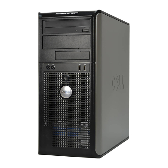
Page 16: Mini Tower Computer
Mini Tower Computer System Views Front View 5.25-inch drive Can contain an optical drive. Insert a CD or DVD (if supported) into this drive. 5.25-inch drive Can contain an optical drive. Insert a CD or DVD (if supported) into this drive. Quick Reference Guide... - Page 17 3.5-inch drive Can contain an optional floppy drive or optional media card reader. USB 2.0 Use the front USB connectors for devices that you connect connectors (2) occasionally, such as joysticks or cameras, or for bootable USB devices (see your online User’s Guide for more information on booting to a USB device).
- Page 18 power light The power light illuminates and blinks or remains solid to indicate different operating modes: • No light — The computer is turned off. • Steady green — The computer is in a normal operating state. • Blinking green — The computer is in a power-saving mode •...
- Page 19 Back View 1 cover-release This latch allows you to open the computer cover. latch 2 padlock ring Insert a padlock to lock the computer cover. Quick Reference Guide...
- Page 20 3 voltage selection Your computer is equipped with a manual voltage-selection switch switch. To help avoid damaging a computer with a manual voltage-selection switch, set the switch for the voltage that most closely matches the AC power available in your location.
- Page 21 2 link integrity light • Green — A good connection exists between a 10-Mbps network and the computer. • Orange — A good connection exists between a 100-Mbps network and the computer. • Yellow — A good connection exists between a 1-Gbps (or 1000-Mbps) network and the computer.
-
Page 22: Removing The Computer Cover
8 video connector Plug the cable from your VGA-compatible monitor into the blue connector. NOTE: If you purchased an optional graphics card, this connector will be covered by a cap. Connect your monitor to the connector on the graphics card. Do not remove the cap. NOTE: If you are using a graphics card that supports dual monitors, use the y-cable that came with your computer. - Page 23 security cable slot cover release latch padlock ring Quick Reference Guide...
-
Page 24: Inside Your Computer
Inside Your Computer CAUTION: Before you begin any of the procedures in this section, follow the safety instructions located in the Product Information Guide. CAUTION: To avoid electrical shock, always unplug your computer from the electrical outlet before removing the computer cover. NOTICE: Be careful when opening the computer cover to ensure that you do not accidentally disconnect cables from the system board. -
Page 25: System Board Components
System Board Components Quick Reference Guide... -
Page 26: Jumper Settings
speaker connector (INT_SPKR) 12 RTC reset jumper (RTCRST) fan (FAN_CPU) 13 intrusion switch connector (INTRUDER) processor connector (CPU) 14 battery socket (BATTERY) processor power connector 15 PCI Express x16 connector (SLOT1) (12VPOWER) memory module connectors 16 PCI Express x1 connector (SLOT4) (DIMM_1, DIMM_2, DIMM_3, DIMM_4) password jumper (PSWD) -
Page 27: Desktop Computer
Jumper Setting Description RTCRST The real-time clock has not been reset. The real-time clock is being reset (jumpered temporarily). jumpered unjumpered Desktop Computer System Views Front View USB 2.0 Use the front USB connectors for devices that you connect connectors (2) occasionally, such as joysticks or cameras, or for bootable USB devices (see "System Setup"... - Page 28 If your operating system has ACPI enabled, when you press the power button the computer will perform an operating system shutdown. Dell badge This badge can be rotated to match the orientation of your computer. To rotate, place fingers around the outside of the badge, press firmly, and turn the badge.
- Page 29 headphone Use the headphone connector to attach headphones and connector most kinds of speakers. microphone Use the microphone connector to attach a microphone. connector 3.5-inch drive Can contain an optional floppy drive, second hard drive, or optional media card reader. 5.25-inch drive Can contain an optical drive.
- Page 30 4 voltage selection Your computer is equipped with a manual voltage selection switch switch. To help avoid damaging a computer with a manual voltage selection switch, set the switch for the voltage that most closely matches the AC power available in your location.
- Page 31 2 link integrity light • Green — A good connection exists between a 10-Mbps network and the computer. • Orange — A good connection exists between a 100-Mbps network and the computer. • Yellow — A good connection exists between a 1-Gbps (or 1000-Mbps) network and the computer.
-
Page 32: Removing The Computer Cover
8 video connector Plug the cable from your VGA-compatible monitor into the blue connector. NOTE: If you purchased an optional graphics card, this connector will be covered by a cap. Connect your monitor to the connector on the graphics card. Do not remove the cap. NOTE: If you are using a graphics card that supports dual monitors, use the y-cable that came with your computer. -
Page 33: Inside Your Computer
security cable slot cover release latch padlock ring Inside Your Computer CAUTION: Before you begin any of the procedures in this section, follow the safety instructions in the Product Information Guide. CAUTION: To avoid electrical shock, always unplug your computer from the electrical outlet before removing the computer cover. - Page 34 drive bays (media card reader power supply or floppy drive, optical drive and hard drive) optional chassis-intrusion system board switch card slots heat sink assembly front I/O panel Quick Reference Guide...
-
Page 35: System Board Components
System Board Components Quick Reference Guide... -
Page 36: Jumper Settings
internal speaker (INT_SPKR) 12 intrusion switch connector (INTRUDER) processor connector (CPU) 13 battery socket (BATTERY) processor power connector 14 PCI Express x16 connector (SLOT1) (12VPOWER) memory module connectors 15 PCI connector (SLOT2) (DIMM_1, DIMM_2, DIMM_3, DIMM_4) password jumper (PSWD) 16 PCI connector (SLOT3) SATA connectors (SATA0, SATA1, 17 riser connector (uses PCI-E SATA2) -
Page 37: Small Form Factor Computer
Jumper Setting Description RTCRST The real-time clock has not been reset. The real-time clock is being reset (jumpered temporarily). jumpered unjumpered Small Form Factor Computer System Views Front View USB 2.0 Use the front USB connectors for devices that you connect connectors (2) occasionally, such as joysticks or cameras, or for bootable USB devices (see "System Setup"... - Page 38 If your operating system has ACPI enabled, when you press the power button the computer will perform an operating system shutdown. Dell badge Can be rotated to match the orientation of your computer. To rotate, place fingers around the outside of the badge, press firmly, and turn the badge.
- Page 39 "Power Management for Windows XP and Vista" in the User’s Guide. See "Dell Diagnostics" on page 61 for a description of light codes that can help you troubleshoot problems with your computer.
- Page 40 Back View 1 card slots (2) Access connectors for any installed PCI cards, PCI Express cards, PS/2, eSATA, and so on. 2 back panel Plug serial, USB, and other devices into the appropriate connectors connectors (see "Back Panel Connectors" on page 41). 3 power connector Insert the power cable.
- Page 41 Back Panel Connectors 1 parallel connector Connect a parallel device, such as a printer, to the parallel connector. If you have a USB printer, plug it into a USB connector. NOTE: The integrated parallel connector is automatically disabled if the computer detects an installed card containing a parallel connector configured to the same address.
- Page 42 3 network adapter To attach your computer to a network or broadband device, connector connect one end of a network cable to either a network jack or your network or broadband device. Connect the other end of the network cable to the network adapter connector on the back panel of your computer.
-
Page 43: Removing The Computer Cover
8 video connector Plug the cable from your VGA-compatible monitor into the blue connector. NOTE: If you purchased an optional graphics card, this connector will be covered by a cap. Connect your monitor to the connector on the graphics card. Do not remove the cap. NOTE: If you are using a graphics card that supports dual monitors, use the y-cable that came with your computer. -
Page 44: Inside Your Computer
security cable slot cover release latch computer cover Inside Your Computer CAUTION: Before you begin any of the procedures in this section, follow the safety instructions in the Product Information Guide. CAUTION: To avoid electrical shock, always unplug your computer from the electrical outlet before removing the computer cover. - Page 45 drive-release latch optical drive power supply hard drive system board heat sink assembly Quick Reference Guide...
-
Page 46: System Board Components
System Board Components Quick Reference Guide... -
Page 47: Jumper Settings
internal speaker connector 12 RTC reset jumper (RTCRST) (INT_SPKR) processor connector (CPU) 13 intrusion switch connector (INTRUDER) processor power connector 14 battery socket (BATTERY) (12VPOWER) memory module connectors 15 PCI Express x16 connector (SLOT1) (DIMM_1, DIMM_2, DIMM_3, DIMM_4) password jumper (PSWD) 16 PCI connector (SLOT2) SATA connectors (SATA0, SATA1) 17 serial connector (SERIAL2) -
Page 48: Ultra Small Form Factor Computer
NOTE: If you want to orient your computer under a desk top or on a wall surface, use the optional wall-mount bracket. contact Dell (see "Contacting Dell" in the User’s Guide). To order this bracket Front View Quick Reference Guide... - Page 49 1 USB connectors Use the front USB connectors for devices that you connect occasionally, such as joysticks or cameras, or for bootable USB devices (see "System Setup" in the User’s Guide for more information about booting to a USB device). It is recommended that you use the back USB connectors for devices that typically remain connected, such as printers and keyboards.
- Page 50 8 hard drive access The hard drive access light is on when the computer reads light data from or writes data to the hard drive. The light might also be on when devices such as your CD player are operating. 9 vents The vents help prevent your computer from overheating.
- Page 51 Back View diagnostic lights See "Diagnostic Lights" on page 66 for a description of light codes that can help you troubleshoot problems with your computer. computer cover release Rotate this knob in a clockwise direction to remove knob the cover. back panel connectors See "Back Panel Connectors"...
- Page 52 Back Panel Connectors parallel Connect a parallel device, such as a printer, to the parallel connector connector. If you have a USB printer, plug it into a USB connector. link integrity • Green — A good connection exists between a 10-Mbps light network and the computer.
- Page 53 network activity The amber light flashes when the computer is transmitting light or receiving network data. A high volume of network traffic may make this light appear to be in a steady "on" state. line-out Use the green line-out connector to attach an amplified connector speaker set.
- Page 54 cable adapter VGA connector monitor cable Connecting Two Monitors cable adapter Use the cable adapter to connect a VGA monitor and a DVI monitor to the DVI-I connector on the back panel. Quick Reference Guide...
-
Page 55: Removing The Computer Cover
When you connect two monitors, the video driver will detect this connection and activate the multimonitor functionality. Removing the Computer Cover CAUTION: Before you begin any of the procedures in this section, follow the safety instructions in the Product Information Guide. NOTICE: To prevent static damage to components inside your computer, discharge static electricity from your body before you touch any of your computer’s electronic... -
Page 56: Inside Your Computer
release knob Inside Your Computer CAUTION: Before you begin any of the procedures in this section, follow the safety instructions in the Product Information Guide. CAUTION: To avoid electrical shock, always unplug your computer from the AC power adapter before removing the cover. NOTICE: To prevent static damage to components inside your computer, discharge static electricity from your body before you touch any of your computer’s electronic... -
Page 57: Cable Cover (Optional)
fan shroud/heat sink assembly speaker (optional) memory modules (2) hard drive security cable slot chassis intrusion switch Cable Cover (Optional) Attaching the Cable Cover 1 Ensure that all external device cables are threaded through the hole in the cable cover. 2 Connect all device cables to the connectors on the back of the computer. - Page 58 cable cover security cable slot Removing the Cable Cover 1 If a security device is installed in the security cable slot, remove the device. release button 2 Slide the release button, grasp the cable cover, and slide the cover sideways as shown until it stops, and then lift the cable cover up and away.
-
Page 59: System Board Components
System Board Components Quick Reference Guide... -
Page 60: Jumper Settings
1 fan connector (FAN_FRONT) password jumper (PSWD) 2 internal speaker connector hard drive fan connector (FAN_HDD) (INT_SPKR) 3 system board speaker (BEEP) 10 clear CMOS jumper (RTCRST) 4 channel B memory connector 11 hard drive power connector (SATA_PWR) (DIMM_2) 5 channel A memory connector 12 fan connector (FAN_REAR) (DIMM_1) 6 SATA data cable connector... -
Page 61: Solving Problems
Solving Problems Dell provides a number of tools to help you if your computer does not perform as expected. For the latest troubleshooting information available for your computer, see the Dell Support website at support.dell.com. If computer problems occur that require help from Dell, write a detailed... - Page 62 Start the Dell Diagnostics from either your hard drive or from the Drivers and Utilities media (an optional CD). See "Starting the Dell Diagnostics From Your Hard Drive" on page 62 or "Starting the Dell Diagnostics From the Drivers and Utilities CD (Optional)" on page 63 for more information.
- Page 63 6 Type 1 to start the Drivers and Utilities CD menu. 7 Type 2 to start the Dell Diagnostics. 8 Select Run the 32 Bit Dell Diagnostics from the numbered list. If multiple versions are listed, select the version appropriate for your computer.
- Page 64 The Service Tag for your computer is located at the top of each test screen. If you contact Dell, technical support will ask for your Service Tag. Your computer’s Service Tag is listed in the System Info option in system setup. See "System Setup" in the User’s Guide for more information.
-
Page 65: System Lights
4 When the tests are completed, if you are running the Dell Diagnostics from the Drivers and Utilities CD, remove the CD. 5 When the tests are complete, close Close the test screen to return to the Main Menu screen. To exit the Dell Diagnostics and restart the computer, close the Main Menu screen. -
Page 66: Diagnostic Lights
POST contact Dell for technical assistance (see "Contacting Dell" in the User’s Guide). Diagnostic Lights CAUTION: Before you begin any of the procedures in this section, follow the safety instructions in the Product Information Guide. - Page 67 The diagnostic lights are not lit after the system successfully • If the problem persists, boots to the operating system. contact Dell (see "Contacting Dell" in the User’s Guide). A possible processor failure has • Reseat the processor (see occurred. Processor information for your system).
- Page 68 • If the problem persists, contact Dell (see "Contacting Dell" in the User’s Guide). A possible floppy drive or hard Reseat all power and data cables. drive failure has occurred. A possible USB failure has Reinstall all USB devices and occurred.
- Page 69 (see the specifications for your system). • If the problem persists, contact Dell (see "Contacting Dell" in the User’s Guide). A possible expansion card failure Determine if a conflict exists has occurred. by removing an expansion card...
-
Page 70: Beep Codes
Reseating the memory modules may correct the following beep code errors. If the problem persists, contact Dell (see "Contacting Dell" in the User’s Guide) for instructions on obtaining technical assistance. - Page 71 1-3-1 through Memory not being properly identified or used 2-4-4 4-3-1 Memory failure above address 0FFFFh If you experience any of the following beep code errors, see "Contacting Dell" for instructions on obtaining technical assistance. in the User’s Guide Code Cause...
-
Page 72: Resolving Software And Hardware Incompatibilities
Code Cause 4-2-1 No timer tick 4-2-2 Shutdown failure 4-2-3 Gate A20 failure 4-2-4 Unexpected interrupt in protected mode 4-3-1 Memory failure above address 0FFFFh 4-3-3 Timer-chip counter 2 failure 4-3-4 Time-of-day clock stopped 4-4-1 Serial or parallel port test failure 4-4-2 Failure to decompress code to shadowed memory 4-4-3... -
Page 73: Restoring Your Operating System
Make regular backups of your data files. System Restore does not monitor your data files or recover them. NOTE: The procedures in this document were written for the Windows default view, so they may not apply if you set your Dell™ computer to the Windows Classic view. Quick Reference Guide... - Page 74 Starting System Restore Windows XP: NOTICE: Before you restore the computer to an earlier operating state, save and close any open files and exit any open programs. Do not alter, open, or delete any files or programs until the system restoration is complete. 1 Click Start→...
-
Page 75: Using Dell™ Pc Restore And Dell Factory Image Restore
If possible, back up the data before using these options. Use PC Restore or Dell Factory Image Restore only if System Restore did not resolve your operating system problem. - Page 76 NOTICE: Removing Dell PC Restore from the hard drive permanently deletes the PC Restore utility from your computer. After you have removed Dell PC Restore, you will not be able to use it to restore your computer operating system. Dell PC Restore enables you to restore your hard drive to the operating state it was in when you purchased your computer.
- Page 77 7 Click Finish to close the PC Restore Removal window and restart the computer. Windows Vista: Dell Factory Image Restore 1 Turn on the computer. When the Dell logo appears, press <F8> several times to access the Vista Advanced Boot Options Window. 2 Select Repair Your Computer.
-
Page 78: Using The Drivers And Utilities Media
6 Click Next. The Confirm Data Deletion screen appears. NOTICE: If you do not want to proceed with Factory Image Restore, click Cancel. 7 Click the checkbox to confirm that you want to continue reformatting the hard drive and restoring the system software to the factory condition, then click Next. -
Page 79: Reinstalling Drivers And Utilities
Reinstalling Drivers and Utilities NOTICE: The Dell Support website at support.dell.com and your Drivers and Utilities media provide approved drivers for Dell™ computers. If you install drivers obtained from other sources, your computer might not work correctly. Using Windows Device Driver Rollback... - Page 80 3 Right-click the device for which the new driver was installed and click Properties. 4 Click the Drivers tab→ Roll Back Driver. If Device Driver Rollback does not resolve the problem, then use System Restore (see "Restoring Your Operating System" on page 73) to return your computer to the operating state that existed before you installed the new driver.
- Page 81 5 Click the Driver tab→ Update Driver→ Browse my computer for driver software. 6 Click Browse and browse to the location to which you previously copied the driver files. 7 When the name of the appropriate driver appears, click the name of the driver→...
- Page 82 Quick Reference Guide...
-
Page 83: Index
73 ergonomics information, 6 cover error messages opening, 22, 32, 43 beep codes, 70 diagnostic lights, 65-66 Dell support site, 8 diagnostic lights, 65-66 Factory Image Restore, 75, 77 diagnostics beep codes, 70 lights, 65-66 documentation... - Page 84 installing parts PC Restore, 75 before you begin, 13, 61 power recommended tools, 13 light, 28, 39 turning off your computer, 13 power button light, 65 problems beep codes, 70 diagnostic lights, 65-66 labels restore to previous state, 73 Microsoft Windows, 7 Product Information Guide, 6 Service Tag, 7 lights...
- Page 85 troubleshooting diagnostic lights, 65-66 Help and Support Center, 9 restore to previous state, 73 User’s Guide, 6 warranty information, 6 Windows Vista Factory Image Restore, 75 System Restore, 73 Windows XP Device Driver Rollback, 79 Help and Support Center, 9 PC Restore, 75 reinstalling, 9 System Restore, 73...
- Page 86 Index...
- Page 87 Dell™ OptiPlex™ 755 クイックリファレンスガイド DCTR DCNE DCSM DCCY モデル 、 、 、および w w w . d e l l . c o m | s u p p o r t . d e l l . c o m...
- Page 88 メモ、注意、警告 メモ コンピュータを使いやすくするための重要な情報を説明しています。 注意 ハードウェアの損傷やデータの損失の可能性を示し、その危険を回避するた めの方法を説明しています。 警告 物的損害、けが、または死亡の原因となる可能性があることを示してい ます。 ____________________ この文書の情報は、事前の通知なく変更されることがあります。 すべての著作権は にあります。 © 2007 Dell Inc. の書面による許可のない複写は、いかなる形態においても厳重に禁じられています。 Dell Inc. 本書に使用されている商標: 、 のロゴ、 、 、 、 、 Dell DELL OptiPlex Inspiron Dimension Latitude Dell 、 、 、 、 、 、...
- Page 89 目次 ......... . .
- Page 90 ......... . . Dell Diagnostics ..
- Page 91 情報の検索方法 メモ メモ メディア • Drivers and Utilities メモ Drivers and Utilities • • DSS Dell Diagnostics Dell Diagnostics Readme Readme メモ support.jp.dell.com...
- Page 92 • メモ • Dell Diagnostics • • • • • メモ support.jp.dell.com 製品情報ガイド • Dell™ • • • ユーザーズガイド • Dell™ OptiPlex™ Microsoft Windows • → Start Help • → Support • Dell User and System Guides → System Guides...
- Page 93 ® サービスタグおよび • Microsoft ® ライセンス Windows • Microsoft Windows support.jp.dell.com • • メモ Microsoft Windows デルサポートサイト • — — Q&A support.jp.dell.com メモ • — • — • Dell Update Service — • — • —...
- Page 94 • DSS — support.jp.dell.com メモ : support.jp.dell.com Dell ヘルプとサポートセンター • Windows XP Windows Windows • • スタート • Windows XP ヘルプとサポート • Windows Vista™ Windows Vista Help and Support オペレーティングシステムメディア • メモ...
- Page 95 Drivers and Utilities Product key メモ コンピュータのセットアップ 警告 注意 注意 メモ...
- Page 96 注意 PS/2 注意 メモ 注意 注意 100 V 115 V 115 V...
- Page 97 キーボードおよびマウスのセットアップ モニターのセットアップ...
- Page 98 電源の接続 作業を開始する前に • • Dell™ • 奨励するツール • • • BIOS...
- Page 99 コンピュータの電源を切る 注意 ® ® Microsoft Windows スタート → シャットダウン → シャットダウン ® ™ Microsoft Windows Vista Windows Vista Start Shut Down 注意 コンピュータ内部の作業をする前に 警告 警告 注意 格 技術者 許可 証 注意 外 分 ち 身 引 外 抜 抜 際 曲...
- Page 100 注意 内 始 次 順 注意 外 外 次 外 警告 • • • • 注意 内 触 金 塗装 金 触 身体 静 除去 期 塗装 金 触 内蔵 静 除去...
- Page 101 ミニタワーコンピュータ システム表示 正面図 5.25 5.25...
- Page 102 USB 2.0 ( デバイスからの起動についての詳細は、 『ユーザーズガイ ド』の「セットアップユーティリティ」を参照してください) 。 注意 代 関 注意 ACPI 有効 消灯 コンピュータの電源は切れています。 • — 緑色の点灯 コンピュータは、通常の動作状態です。 • — 緑色の点滅 コンピュータは、省電力モードです。 • — 黄色の点滅または点灯 コンピュータに電力は供給されて • — いるが、内部電源に問題がある可能性があります( 『ユー ザーズガイド』の「電源の問題」を参照) 。 Windows...
- Page 104 背面図...
- Page 105 注意 115 V 要 PCI Express PS/2 eSATA 背面パネルコネクタ メモ 内蔵 検 内蔵 無効 関 ズ...
- Page 106 緑色 ネットワークとコンピュータ間の接続が良 • — 10 Mbps 好です。 橙色 ネットワークとコンピュータ間の接続が • — 100 Mbps 良好です。 黄色 (または )ネットワークと • — 1 Gbps 1000 Mbps コンピュータ間の接続が良好です。 オフ コンピュータは物理的なネットワーク接続を検出し • — ていません。 メモ 10 Mbps 話 音声 音楽 7 USB 2.0...
- Page 107 ビ 互換 メモ 購 外 メモ 指 先 COM1 COM2 コンピュータカバーの取り外し 警告 警告 警告...
- Page 109 コンピュータの内部 警告 警告 注意 際 基板 外 意 装 基板 ヒ ハ...
- Page 110 システム基板コンポーネント...
- Page 111 12 RTC INT_SPKR RTCRST FAN_CPU INTRUDER BATTERY 15 PCI Express x16 12 V SLOT1 16 PCI Express x1 SLOT4 DIMM_1 DIMM_2 DIMM_3 DIMM_4 17 PCI PSWD SLOT2 18 PCI SATA SATA0 SLOT3 SATA1 SATA2 SATA3 FRONTPANEL SERIAL2 基板 POWER BEEP 外...
- Page 112 RTCRST せ デスクトップコンピュータ システム表示 正面図 USB 2.0...
- Page 113 注意 代 関 ズ 注意 ACPI 有効 回転 せ 向 わせ 回転 せ 外回 指 置 回 側 近 回転 せ 消灯 コンピュータの電源は切れています。 • — 緑色の点灯 コンピュータは、通常の動作状態です。 • — 緑色の点滅 コンピュータは、省電力モードです。 • — 黄色の点滅または点灯 『ユーザーズガイド』の「電源の • — 問題」を参照してください。 Windows Windows XP Vista...
- Page 114 台目 装着 5.25 背面図 PCI Express PS/2 eSATA メモ 図 正 装備 注意 115 V 要...
- Page 115 背面パネルコネクタ メモ 内蔵 検 内蔵 無効 関 ズ 緑色 ネットワークとコンピュータ間の接続が良 • — 10 Mbps 好です。 橙色 ネットワークとコンピュータ間の接続が • — 100 Mbps 良好です。 黄色 (または )ネットワークと • — 1 Gbps 1000 Mbps コンピュータ間の接続が良好です。 オフ コンピュータは物理的なネットワーク接続を検出し • — ていません。...
- Page 116 メモ 10 Mbps 話 音声 音楽 7 USB 2.0 ビ 互換 メモ 購 外 メモ 指 先 COM1 COM2...
- Page 117 コンピュータカバーの取り外し 警告 警告 警告...
- Page 118 コンピュータの内部 警告 警告 注意 際 基板 外 意...
- Page 119 装 ハ 基板 ヒ...
- Page 120 システム基板コンポーネント...
- Page 121 内蔵 INT_SPKR INTRUDER BATTERY PCI Express x16 SLOT1 12 V SLOT2 DIMM_1 DIMM_2 DIMM_3 DIMM_4 PSWD SLOT3 SATA SATA0 SATA1 PCI-E SATA2 SLOT1 / SLOT2 SERIAL2 FRONTPANEL 基板 POWER BEEP 外 補助 SATA eSATA LED aux_LED 内蔵 USB INT_USB DSKT RTCRST FAN_CPU ジャンパ設定...
- Page 122 RTCRST せ スモールフォームファクターコンピュータ システム表示 正面図 USB 2.0...
- Page 123 ACPI 有効 回転 せ 向 わせ 回転 せ 外回 指 置 回 側 近 回転 せ 消灯 コンピュータの電源は切れています。 • — 緑色の点灯 コンピュータは、通常の動作状態です。 • — 緑色の点滅 コンピュータは、省電力モードです。 • — 黄色の点滅または点灯 『ユーザーズガイド』の「電源の • — 問題」を参照してください。 Windows Windows XP Vista 明 Dell Diagnostics...
- Page 124 装着 装着 5.25 背面図 PCI Express PS/2 eSATA 正 注意 115 V 要...
- Page 125 背面パネルコネクタ メモ 内蔵 検 内蔵 無効 関 ズ 緑色 ネットワークとコンピュータ間の接続が良 • — 10 Mbps 好です。 橙色 ネットワークとコンピュータ間の接続が • — 100 Mbps 良好です。 黄色 (または )ネットワークと • — 1 Gbps 1000 Mbps コンピュータ間の接続が良好です。 オフ コンピュータは物理的なネットワーク接続を検出し • — ていません。...
- Page 126 メモ 10 Mbps 搭載 利 搭載 話 音声 音楽 7 USB 2.0 ビ 互換 メモ 購 外 メモ...
- Page 127 コンピュータカバーの取り外し 警告 警告 警告...
- Page 128 コンピュータの内部 警告 警告 注意 際 基板 外 意...
- Page 129 装 ハ 基板 ヒ...
- Page 130 システム基板コンポーネント...
- Page 131 内蔵 RTCRST INT_SPKR INTRUDER BATTERY 12 V PCI Express x16 SLOT1 DIMM_1 DIMM_2 DIMM_3 DIMM_4 PSWD SLOT2 SATA SATA0 SATA1 SERIAL2 基板 BEEP FRONTPANEL 補助 POWER LED aux_LED FAN_HDD DSKT eSATA eSATA FAN_CPU 内蔵 INT_USB ジャンパ設定 PSWD 有効 無効...
- Page 132 RTCRST せ ウルトラスモールフォームファクター コンピュータ システム表示 注意 上 注意 際 引 踏 メモ 机 連絡 ズ 正面図...
- Page 133 1 USB 異 消灯 コンピュータの電源は切れています。 • — 緑色の点灯 コンピュータは、通常の動作状態です。 • — 緑色の点滅 コンピュータは、省電力モードです。 • — 黄色の点滅または点灯 『ユーザーズガイド』の「電源の問 • — 題」を参照してください。 Windows 「 および での電力の管理」 Windows XP Vista 明 注意 関 気孔 気孔 ヒ ぎ 気 冷却 気孔 塞 台目...
- Page 134 読 書 中 気孔 気孔 ヒ ぎ 気 冷却 気孔 塞 側面図 気孔 側 気孔 ヒ ぎ 気 冷却 気孔 塞 穴...
- Page 135 背面図 計回 回 外 気孔 気孔 ヒ ぎ 気 冷却 気孔 塞...
- Page 136 背面パネルコネクタ 緑色 ネットワークとコンピュータ間の接続 • — 10 Mbps が良好です。 橙色 ネットワークとコンピュータ間の接続 • — 100 Mbps が良好です。 黄色 ( )ネットワークとコン • — 1000 Mbps 1 Gbps ピュータ間の接続が良好です。 オフ コンピュータがネットワークへの物理的な接続を • — 検出していないか、ネットワークコントローラがセット アップユーティリティでオフになっています。 メモ 10 Mbps...
- Page 137 話 音声 音楽 ビ 互換 白 ビ モニターの接続...
- Page 138 台のモニターの接続 DVI-I...
- Page 139 コンピュータカバーの取り外し 警告 注意 内 静 子 触 身体 静 除去 塗装 金 触 静 除去 注意 内 触 塗装 金 分 触 身体 静 除去 期 塗装 金 触 内蔵 静 除去 1 cm 警告...
- Page 140 ノ コンピュータの内部 警告 警告 注意 内 静 子 触 身体 静 除去 塗装 金 触 静 除去...
- Page 141 エ ヒ ハ ケーブルカバー(オプション) カーブルカバーの取り付け...
- Page 142 ケーブルカバーの取り外し...
- Page 143 システム基板コンポーネント...
- Page 144 FAN_FRONT PSWD 内蔵 ハ INT_SPKR FAN_HDD 基板 CMOS RTCRST BEEP ハ DIMM_2 SATA_PWR FAN_REAR DIMM_1 SATA SATA0 INTRUDER BATT ジャンパ設定 PSWD 有効 無効...
-
Page 145: Dell Diagnostics
RTCRST せ 問題の解決 support.jp.dell.com ___________________________ ___________________________ (診断)プログラム Dell Diagnostics 警告 (診断)プログラムを使用する場合 Dell Diagnostics Dell Diagnostics 注意 診断 上 Dell Diagnostics Dell™... - Page 146 Drivers and Utilities Dell Diagnostics Dell Diagnostics Drivers and Utilities CD Dell Diagnostics ハードドライブから (診断)プログラムをスタートする場合 Dell Diagnostics Dell Diagnostics メモ DELL™ <F12> メモ 診断 見 知 Drivers and Utilities CD Dell 診断 Diagnostics Drivers and Utilities CD Drivers and Utilities ®...
- Page 147 指 従 起 SATA CD-ROM Device <Enter> SATA CD-ROM Device Boot from CD-ROM Drivers and Utilities CD Dell Diagnostics Run the 32 Bit Dell Diagnostics メインメニュー Dell Diagnostics Dell Diagnostics (診断)プログラムのメインメニュー Dell Diagnostics Dell Diagnostics Main Menu Express Test ~...
- Page 148 Custom Test Symptom Tree Results 結果 発 表 Errors 検 明 表 Help 明 件 Configuration 選択 構成 表 Dell Diagnostics 各 部 構成情報 得 画 左 表 覧 名 名 表 限 せ Parameters Drivers and Utilities CD Dell Diagnostics...
- Page 149 正 処置 せ 操 数回 発 特 別 調 認 Dell Diagnostics Dell Diagnostics 中 中 ば 終了 板 不良 待 正 連絡 わせ 装置 板 障 害 発 中 中 検 ビ POST BIOS ビ ビ 特 別 認...
- Page 150 中 板 欠陥 特 別 POST ビ 調 認 特 連絡 わせ 診断ライト 警告 1 2 3 メモ 消灯 POST 起 • 障害 BIOS • 正 消 障害 • •...
- Page 151 検 • 2 障害 発 • • 障害 • 発 • • 障害 発 抜 障害 発 認...
- Page 152 検 • 2 せ • • 検 • 互換 発 • • わ せ...
- Page 153 拡張 障害 発...
- Page 154 障害 発 • • • • ビープコード 1-3-1...
- Page 155 ~ 正 認 1-3-1 2-4-4 4-3-1 上 障害 0FFFFh 1-1-2 障害 1-1-3 読 書 障害 NVRAM 1-1-4 障害 ROM BIOS 1-2-1 障害 1-2-2 初期化障害 1-2-3 読 書 障害 ビ 障害 ~ 正 認 1-3-1 2-4-4 3-1-1 障害 3-1-2 障害 3-1-3 割...
- Page 156 4-2-2 失敗 4-2-3 Gate A20 4-2-4 予期せぬ割 4-3-1 上 障害 0FFFFh 4-3-3 障害 4-3-4 部 計 停止 4-4-1 障害 4-4-2 凍不 4-4-3 数値演算 障害 4-4-4 障害 ソフトウェアおよびハードウェアの非互換性の解決 Windows XP スタート → ヘルプとサポート ハードウェアに関するトラブルシューティング <Enter> 問題を解決する ハードウェアに関するトラブルシューティン グ ハードウェアに関するトラブルシューティング 次へ Windows Vista Windows Vista Help and Support...
-
Page 157: Microsoft Windows
お使いのオペレーティングシステムの復元 • • Symantec Dell PC Windows XP Dell Factory Image Restore Windows Vista Dell PC Dell Factory Image Restore • システムの復元 Microsoft Windows Microsoft Windows 注意 期 復元 監視 復元 メモ 順 ォ Windows Dell™ Windows... - Page 158 システムの復元の開始 Windows XP 注意 以 状態 復元 復元 完 変更 削除 スタート → すべてのプログラム → アクセサリ → システムツール → システ ムの復元 コンピュータを以前の状態に復元する 復元ポイントの作成 次へ Windows Vista Start System Restore <Enter> : User Account Control メモ 管 者 管 者 Continue 管...
- Page 159 Windows XP 200 MB Windows XP スタート → コントロールパネル → パフォーマンスとメンテナンス → シス テム システムの復元 すべてのドライブでシステムの復元 を無効にする リストアおよび の使い方 Dell™ PC Dell Factory Image Restore 注意 ハ Dell PC Dell Factory Image Restore 完全 削除 元 届 削除 復元 題 解決...
- Page 160 : リストア Windows XP Dell PC www.dell.com <Ctrl><F11> <Ctrl><F11> 注意 以上進 再起動 復元 確認 終了 メモ 終了 完全 再起 はい 次へ システムの復元 注意 ハ 永久 削除 Dell PC 削除 除 Dell PC 復元...
-
Page 161: Image Restore
Dell Factory Image Restore Dell <F8> Vista Advanced Boot Options Window Vista Repair Your Computer System Recovery Options Next administrator Dell Factory Image Restore メモ ツ Dell Factory Tools Dell Factory 要 Dell Factory Image Restore Dell Factory Image Restore... -
Page 162: Drivers And Utilities
Next Confirm Data Deletion 注意 以上進 Factory Image Restore Cancel Next Finish メディアの使い方 Drivers and Utilities 注意 Drivers and Utilities 収録 Microsoft Windows • • • ドライバの識別 ® ® Microsoft Windows スタート → コントロールパネル 作業する分野を選びます パフォーマンスとメンテナンス システム システムプロパティ ハードウェア デバイスマネージャ... - Page 163 → Properties Device Manager メモ User Account Control 管 者 Continue 管 者 管 者 ドライバとユーティリティの再インストール 注意 support.jp.dell.com Drivers and 承 提供 Utilities Dell™ 媒体 デバイスドライバのロールバックの使い方 Windows Windows Windows XP スタート → マイコンピュータ → プロパティ → ハードウェア → デバイスマ ネージャ...
- Page 164 Properties → Drivers Roll Back Driver ドライバの手動再インストール Windows XP スタート → マイコンピュータ → プロパティ → ハードウェア → デバイスマ ネージャ オーディオ ビデオ ドライバ → ドライバの更新 一覧または特定の場所からインストールする(詳細設定)→ 次へ 参照 次へ 完了 Windows Vista Windows Vista Computer → Properties Device Manager メモ User Account Control 管...
- Page 165 → → Driver Update Driver Browse my computer for driver software Browse → → Next Finish...
- Page 167 索引 あ , 94 え Diagnostics , 154 , 154 , 148, 150 Factory Image Restore , 159, お , 94 CD , 94 , 159 か Windows Vista , 117, 127 Factory Image Restore , 159 , 107 , 157 Windows XP , 159 こ...
- Page 168 さ と , 93 , 163 , 92 , 162 , 93 , 94 , 157 し , 157 , 148 , 110, 120, 143 , 157 , 150 , 148 , 148, 150 に , 92 せ , 92 は...
- Page 169 へ ら , 94 , 148, 150 , 148 Windows , 148, 150 , 94 , 113, 123 , 148 ま Microsoft Windows , 93 , 93 , 92 , 92 , 93 , 92 , 92 , 92 , 92 も...
- Page 170 索引...