
Related Manuals for GEM 650TL


Summary of Contents for GEM 650TL
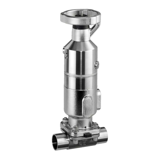
- Page 1 GEMÜ 650TL Manually operated diaphragm valve Operating instructions further information webcode: GW-650TL...
- Page 2 All rights including copyrights or industrial property rights are expressly reserved. Keep the document for future reference. © GEMÜ Gebr. Müller Apparatebau GmbH & Co. KG 13.02.2024 GEMÜ 650TL 2 / 42 www.gemu-group.com...
-
Page 3: Table Of Contents
12.2 Connecting the control medium ....13 Stroke limiter and seal adjuster ......13.1 Setting the seal adjuster (GEMÜ 650 0TL) .. 13.2 Setting the closing and opening stroke lim- iter (GEMÜ 650 1TL/650 2TL) ...... 14 Proximity switches .......... -
Page 4: General Information
The medium that flows through the GEMÜ product. Symbol Meaning Diaphragm size Danger of explosion! Uniform seat size of GEMÜ diaphragm valves for different nominal sizes. Control function Corrosive chemicals! The possible actuation functions of the GEMÜ product. Control medium... -
Page 5: Description ..................................................... 5 19 Disposal
(see Conexo informa- 15. Consult the nearest GEMÜ sales office. tion) 3.2 Description Diaphragm valve GEMÜ 650TL is a manually operated dia- phragm valve with a pneumatic fail safe function. The valve can only be operated manually (opened/closed) if the actu- www.gemu-group.com 5 / 42 GEMÜ... -
Page 6: Function ......................................................... 6 20 Returns
GEMÜ 650 0TL test reports, testing documentation and maintenance histor- ies. The CONEXO portal acts as a central element, helping to collect, manage and process all data. For further information on GEMÜ CONEXO please visit: www.gemu-group.com/conexo 5 Correct use Valve open*... -
Page 7: Order Data
D control air connector and connections for proximity Clamp DIN 32676 series B, switches face-to-face dimension FTF EN 558 series 7, positioned in-line with flow direction length only for body configuration D www.gemu-group.com 7 / 42 GEMÜ 650TL... - Page 8 D switches positioned in-line with flow direction 11 Surface Code 9 DN-2 Code Ra ≤ 6.3 μm (250 μin.) for media wetted surfaces, 1500 mechanically polished internal DN 4 GEMÜ 650TL 8 / 42 www.gemu-group.com...
-
Page 9: Order Example
Spigot ISO 1127/DIN EN 10357 series C (2014 edition)/DIN 11866 series B 11 Surface 1503 Ra ≤ 0.8 µm (30 µin.) for media wetted surfaces, in accordance with DIN 11866 HE3, electropolished internal/external 12 Special version Special version for 3A 13 CONEXO Without www.gemu-group.com 9 / 42 GEMÜ 650TL... -
Page 10: Technical Data
PTFE diaphragms exposed to high temperature fluctuations. The maintenance cycles must be adapted accordingly. GEMÜ 555 and 505 globe valves are particularly suitable for use in the area of steam generation and distribution. The following valve arrangement for interfaces between steam pipes and process pipes has proven itself over time: A globe valve for shutting off steam pipes and a diaphragm valve as an interface to the process pipes. -
Page 11: Product Conformity
HFT (Hardware Fault Tolerance): 0 MTTR (Mean Time To Restora- 24 hours tion): Product description: GEMÜ diaphragm valve 650TLwith GEMÜ 032x pilot solenoid valve Device type: Fail safe function: Due to the fail safe function, the diaphragm valve is placed in the closed position (with control function 1). -
Page 12: Mechanical Data
ØB ØB1 Actuator ver- ØB ØB1 sion 0TL, 0RL, 0LL 146.0 26.5 42.0 32.0 G 1/8 Dimensions in mm MG = diaphragm size * CT = A + H1 (see body dimensions) GEMÜ 650TL 12 / 42 www.gemu-group.com... - Page 13 Actuator ver- ØB ØB1 sion 1TL, 1RL, 1LL, 196.0 37.0 27.0 60.0 G 1/8 1HL, 1ML, 1SL Dimensions in mm MG = diaphragm size * CT = A + H1 (see body dimensions) www.gemu-group.com 13 / 42 GEMÜ 650TL...
- Page 14 Actuator ver- ØB ØB1 sion 2TL, 2RL, 2LL, 264.0 51.0 24.0 85.0 G 1/4 2HL, 2ML, 2SL Dimensions in mm MG = diaphragm size * CT = A + H1 (see body dimensions) GEMÜ 650TL 14 / 42 www.gemu-group.com...
-
Page 15: Body Dimensions Of 2/2-Way Body
Code 60: Spigot ISO 1127/DIN EN 10357 series C (2014 edition)/DIN 11866 series B 2) Valve body material Code 40: 1.4435 (F316L), forged body Code 42: 1.4435 (BN2), forged body, Δ Fe < 0.5% Code F4: 1.4539, forged body www.gemu-group.com 15 / 42 GEMÜ 650TL... - Page 16 Code 17: Spigot EN 10357 series A/DIN 11866 series A formerly DIN 11850 series 2 Code 60: Spigot ISO 1127/DIN EN 10357 series C (2014 edition)/DIN 11866 series B 2) Valve body material Code C3: 1.4435, investment casting GEMÜ 650TL 16 / 42 www.gemu-group.com...
- Page 17 Code 64: Spigot ANSI/ASME B36.19M schedule 5s Code 65: Spigot ANSI/ASME B36.19M schedule 40s 2) Valve body material Code 40: 1.4435 (F316L), forged body Code 42: 1.4435 (BN2), forged body, Δ Fe < 0.5% Code F4: 1.4539, forged body www.gemu-group.com 17 / 42 GEMÜ 650TL...
- Page 18 Dimensions in mm MG = diaphragm size 1) Connection type Code 59: Spigot ASME BPE/DIN EN 10357 series C (from 2022 edition)/DIN 11866 series C 2) Valve body material Code C3: 1.4435, investment casting GEMÜ 650TL 18 / 42 www.gemu-group.com...
- Page 19 Code 37: Spigot SMS 3008 2) Valve body material Code 40: 1.4435 (F316L), forged body Code 42: 1.4435 (BN2), forged body, Δ Fe < 0.5% Code C3: 1.4435, investment casting Code F4: 1.4539, forged body www.gemu-group.com 19 / 42 GEMÜ 650TL...
- Page 20 Dimensions in mm MG = diaphragm size 1) Connection type Code 6: Threaded spigot DIN 11851 2) Valve body material Code 40: 1.4435 (F316L), forged body Code 42: 1.4435 (BN2), forged body, Δ Fe < 0.5% GEMÜ 650TL 20 / 42 www.gemu-group.com...
- Page 21 MG = diaphragm size 1) Connection type Code 6K: Cone spigot and union nut DIN 11851 2) Valve body material Code 40: 1.4435 (F316L), forged body Code 42: 1.4435 (BN2), forged body, Δ Fe < 0.5% www.gemu-group.com 21 / 42 GEMÜ 650TL...
- Page 22 Code 8: Flange EN 1092, PN 16, form B, face-to-face dimension FTF EN 558 series 1, ISO 5752, basic series 1, length only for body configur- ation D 2) Valve body material Code 39: 1.4408, PFA lined Code 40: 1.4435 (F316L), forged body Code 42: 1.4435 (BN2), forged body, Δ Fe < 0.5% Code C3: 1.4435, investment casting GEMÜ 650TL 22 / 42 www.gemu-group.com...
- Page 23 Code 39: Flange ANSI Class 125/150 RF, face-to-face dimension FTF EN 558 series 1, ISO 5752, basic series 1, length only for body config- uration D 2) Valve body material Code 39: 1.4408, PFA lined Code 40: 1.4435 (F316L), forged body Code 42: 1.4435 (BN2), forged body, Δ Fe < 0.5% Code C3: 1.4435, investment casting www.gemu-group.com 23 / 42 GEMÜ 650TL...
- Page 24 Code 8T: Clamp DIN 32676 series C, face-to-face dimension FTF EN 558 series 7, length only for body configuration D 2) Valve body material Code 40: 1.4435 (F316L), forged body Code 42: 1.4435 (BN2), forged body, Δ Fe < 0.5% Code F4: 1.4539, forged body GEMÜ 650TL 24 / 42 www.gemu-group.com...
-
Page 25: Body Dimensions Of Tank Bottom Valve Body And T Body
Code 42: 1.4435 (BN2), forged body, Δ Fe < 0.5% Code F4: 1.4539, forged body 8.3 Body dimensions of tank bottom valve body and T body Tank bottom valve body and T body: Dimensions and designs on request www.gemu-group.com 25 / 42 GEMÜ 650TL... -
Page 26: Application
However, it does determine the valve position when the con- 4. Do not store solvents, chemicals, acids, fuels or similar trol medium supply is switched back on. fluids in the same room as GEMÜ products and their spare parts. 10.5 Condition as supplied to customer Condition of the product as supplied to customer: Control function 1 (normally closed). -
Page 27: Installation In Piping
4. Weld the body of the product in the piping. 5. Allow butt weld spigots to cool down. 6. Mount the actuator and diaphragm on the valve body. 7. Re-attach or reactivate all safety and protective devices. www.gemu-group.com 27 / 42 GEMÜ 650TL... -
Page 28: Installation With Clamp Connections
3. Screw the pipe into the threaded connection of the valve body in accordance with valid standards. ð Use appropriate thread sealant. 4. Re-attach or reactivate all safety and protective devices. GEMÜ 650TL 28 / 42 www.gemu-group.com... -
Page 29: Connecting The Control Medium
Standard setting: The valve is sealed when the handwheel is completely closed (turned fully clockwise). 13.1 Setting the seal adjuster (GEMÜ 650 0TL) Vent hole Control medium connector 2 Leak detection hole The product has 2 control medium connectors. -
Page 30: Setting The Closing And Opening Stroke Limiter (Gemü 650 1Tl/650 2Tl)
13 Stroke limiter and seal adjuster 13.2 Setting the closing and opening stroke limiter Setting the stroke limiter (GEMÜ 650 1TL/650 2TL) 7. Move the valve to the desired OPEN position by operating the handwheel. Preparation for setting 1. Pull off protective cap a. -
Page 31: Proximity Switches
▶ The proximity switches are adjusted after complete as- ▶ Only use M8x1 proximity switches which can be mounted sembly of the valve. flush. Two proximity switches can be mounted on the GEMÜ 650TL NOTICE for feedback of the closed position from the pneumatic pis- ton 1 and handwheel 2. -
Page 32: Setting The Damping Piece
3. After undoing grub screw e, damping piece b on the valve spindle can be moved to the correct position. 4. Fix the position of damping piece b with grub screw e. 5. Screw threaded plug a back in. GEMÜ 650TL 32 / 42 www.gemu-group.com... -
Page 33: Troubleshooting
Stroke limiter is incorrectly set (only for Reset stroke limiter GEMÜ 650 1TL and 650 2TL) Handwheel is in the closed position Move the handwheel to the open position The product is leaking downstream (does... - Page 34 Release and reset stroke limiter and seal rectly set adjuster Proximity switches also respond in the Use of wrong proximity switches Only use M8x1 proximity switches which open position can be mounted flush Damping piece incorrectly adjusted Reset damping piece GEMÜ 650TL 34 / 42 www.gemu-group.com...
-
Page 35: 18.1 Spare Parts
4. Secure the plant or plant component against recommis- washers, nuts) sioning. Actuator 9650…TL 5. Depressurize the plant or plant component. 6. Actuate GEMÜ products which are always in the same po- sition four times a year. www.gemu-group.com 35 / 42 GEMÜ 650TL... -
Page 36: 18.4 Mounting The Compressor
6. Check parts for potential damage, replace if necessary tion, it must be turned to the correct position. The position of (only use genuine parts from GEMÜ). A is offset by 45° to the position of C. 1. Place the compressor loosely on the actuator spindle. - Page 37 2. Mount the compressor (see "Mounting the compressor"). 3. Check if the compressor is fitted in the guides. 4. Place the diaphragm with the rubber pin in an inclined pos- ition at the recess of the compressor. www.gemu-group.com 37 / 42 GEMÜ 650TL...
- Page 38 8. If it is difficult to screw it in, check the thread and replace damaged parts. 9. When definitive resistance is felt, turn back the diaphragm until its bolt holes are in correct alignment with the bolt holes of the actuator. GEMÜ 650TL 38 / 42 www.gemu-group.com...
- Page 39 If prior to commissioning and during the total term of use. no return delivery note is included with the product, GEMÜ cannot process credits or repair work but will dispose of the 13.
-
Page 40: Ec Machinery Directive 2006/42/Ec, Annex Ii B
EC Machinery Directive 2006/42/EC, Annex II B Machinery Directive introductory text We, the company GEMÜ Gebr. Müller Apparatebau GmbH & Co. KG Fritz-Müller-Strasse 6–8 74653 Ingelfingen-Criesbach, Germany hereby declare under our sole responsibility that the below-mentioned product complies with the relevant essential health and safety requirements in accordance with Annex I of the above-mentioned Directive. -
Page 41: Manufacturer's Declaration According To The Pres- 6 Sure Equipment Directive 2014/68/Eu
Manually operated diaphragm valve The product has been developed and produced according to GEMÜ's in-house process instructions and standards of quality which comply with the requirements of ISO 9001 and ISO 14001. According to Article 4, Paragraph 3 of the Pressure Equipment Directive 2014/68/EU, this product must not be identified by a CE-marking. - Page 42 GEMÜ Gebr. Müller Apparatebau GmbH & Co. KG Fritz-Müller-Straße 6-8, 74653 Ingelfingen-Criesbach, Germany Subject to alteration Phone +49 (0) 7940 1230 · info@gemue.de www.gemu-group.com 02.2024 | 88899546...