Chapters
Table of Contents

Related Manuals for GEM 655


Summary of Contents for GEM 655
- Page 1 Tiefsitzmembranventil Metall, DN 25 - 300 Full Bore Diaphragm Valve Metal, DN 25 - 300 ORIGINAL EINBAU- UND MONTAGEANLEITUNG INSTALLATION, OPERATING AND MAINTENANCE INSTRUCTIONS...
-
Page 2: Table Of Contents
Allgemeine Sicherheitshinweise 2 Sachgerechter Transport und Lagerung Hinweise für Service- Installation und Inbetriebnahme durch und Bedienpersonal eingewiesenes Fachpersonal Warnhinweise Bedienung gemäß dieser Einbau- und Verwendete Symbole Montageanleitung Begriff sbestimmungen Ordnungsgemäße Instandhaltung Vorgesehener Einsatzbereich Technische Daten Korrekte Montage, Bedienung und Wartung Bestelldaten oder Reparatur gewährleisten einen... -
Page 3: Hinweise Für Service
Möglicherweise gefährliche Situation! dürfen nicht ohne vorherige Abstimmung ® Bei Nichtbeachtung drohen mit dem Hersteller durchgeführt werden. Sachschäden. GEFAHR Sicherheitsdatenblätter bzw. die für die verwendeten Medien geltenden Sicherheitsvorschriften unbedingt beachten! Bei Unklarheiten: Bei nächstgelegener GEMÜ- Verkaufsniederlassung nachfragen. 3 / 32... -
Page 4: Verwendete Symbole
Ventil ermittelt. Für die angegebenen Werte ist die Dichtheit am Ventilsitz und nach außen gewährleistet. Angaben zu beidseitig anstehenden Betriebsdrücken und für Reinstmedien auf Anfrage. Kv-Werte ermittelt gemäß DIN EN 60534, Eingangsdruck 5 bar, Δp 1 bar, Ventilkörperwerkstoff Grauguss EN-GJL-250 mit Anschluss Flansch EN 1092 Baulänge EN 558 Reihe 7 und Weichelastomermembrane. -
Page 5: Bestelldaten
Bestelldaten Gehäuseform Code Membranwerkstoff Code Durchgang Anschlussart Code EPDM Flansch EN 1092 / PN10 / Form A, Baulänge FTF EN 558, Reihe 7, ISO 5752, basic series 7 Flansch EN 1092 / PN16 / Form A, Steuerfunktion Code Baulänge FTF EN 558, Reihe 7, Manuell betätigt ISO 5752, basic series 7 Flansch ANSI Class 125/150 FF,... -
Page 6: Herstellerangaben
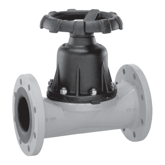
Herstellerangaben Funktionsbeschreibung Das handgesteuerte 2/2-Wege- Tiefsitzmembranventil GEMÜ 655 mit Transport Metallantrieb besitzt ein nichtsteigendes Handrad. Ventilkörper und Membrane Ventil nur auf geeignetem Lademittel transportieren, nicht stürzen, vorsichtig sind gemäß Datenblatt in verschiedenen Ausführungen erhältlich. Das Ventil handhaben. ist nachträglich umrüstbar auf... -
Page 7: Montage Und Bedienung
Verbrühungen überschreiten! ausgeschlossen sind. ® Eventuell auftretende Druckstöße 6. Anlage bzw. Anlagenteil fachgerecht (Wasserschläge) durch dekontaminieren, spülen und belüften. Schutzmaßnahmen vermeiden. Montagearbeiten nur durch geschultes Fachpersonal. Geeignete Schutzausrüstung gemäß den Regelungen des Anlagenbetreibers berücksichtigen. 7 / 32... -
Page 8: Montage / Demontage Von Ersatzteilen
2. Alle Teile von Produktresten und wieder anbringen bzw. in Funktion setzen. Verschmutzungen reinigen. Teile dabei nicht zerkratzen oder beschädigen! 3. Alle Teile auf Beschädigungen prüfen. 11 Montage / Demontage 4. Beschädigte Teile austauschen (nur von Ersatzteilen Originalteile von GEMÜ verwenden). 8 / 32... -
Page 9: Montage Membrane
11.3 Montage Membrane DN 25 - 40: Druckstück und Antriebsflansch von unten gesehen: 11.3.1 Allgemeines Wichtig: Für Ventil passende Membrane einbauen (geeignet für Medium, Mediumkonzentration, Temperatur und Druck). Die Membrane ist ein Verschleißteil. DN 50 - 65: Vor Inbetriebnahme und über Druckstück und Antriebsflansch von unten gesamte Einsatzdauer des Ventils gesehen:... -
Page 10: Montage Der Tiefsitzmembrane
11.3.2 Montage der DN 200: Tiefsitzmembrane Druckstück und Antriebsflansch von unten gesehen: Wichtig: Für Ventil passende Membrane einbauen (geeignet für Medium, Mediumkonzentration, Temperatur und Druck). DN 250: 1. Vor Montage der neuen Membrane Druckstück und Antriebsflansch von unten Antrieb demontieren wie unter gesehen: Kapitel 11.2 "Demontage Membrane"... -
Page 11: Inbetriebnahme
Handhabung oder ® Verätzungen! Fremdeinwirkung entstehen, übernimmt Vor Inbetriebnahme Dichtheit GEMÜ keinerlei Haftung. der Medienanschlüsse Nehmen Sie im Zweifelsfall vor prüfen! Inbetriebnahme Kontakt mit GEMÜ auf. Dichtheitsprüfung nur mit geeigneter 1. Geeignete Schutzausrüstung gemäß Schutzausrüstung. den Regelungen des Anlagenbetreibers VORSICHT berücksichtigen. -
Page 12: Demontage
Umweltschutzbestimmungen entsorgen. Auf Restanhaftungen und Ausgasung von eindiff undierten Medien achten. 16 Rücksendung Ventil reinigen. Rücksendeerklärung bei GEMÜ anfordern. Rücksendung nur mit vollständig ausgefüllter Rücksendeerklärung. Ansonsten erfolgt keine Gutschrift bzw. keine Erledigung der Reparatur sondern eine kostenpflichtige Entsorgung. Hinweis zur Rücksendung:... -
Page 13: Fehlersuche / Störungsbehebung
18 Fehlersuche / Störungsbehebung Fehler Möglicher Grund Fehlerbehebung Betriebsmedium entweicht Membrane auf Beschädigungen prüfen, Membrane defekt aus Leckagebohrung* ggf. Membrane tauschen Antrieb demontieren, Membranmontage Membrane nicht korrekt montiert Ventil öffnet nicht bzw. nicht prüfen, ggf. austauschen vollständig Antrieb defekt Antrieb austauschen Ventil mit Betriebsdruck laut Datenblatt Betriebsdruck zu hoch betreiben... -
Page 14: Schnittbild Und Ersatzteile
19 Schnittbild und Ersatzteile Handrad Leckagebohrung Pos. Benennung Bestellbezeichnung Ventilkörper K655… Tiefsitzmembrane 655…M… Schraube Scheibe 655...S30... Mutter Antrieb 9655... 14 / 32... -
Page 15: Eu-Konformitätserklärung
Die Produkte werden entwickelt und produziert nach GEMÜ eigenen Verfahrensanweisungen und Qualitätsstandards, welche die Forderungen der ISO 9001 und der ISO 14001 erfüllen. Die Produkte dürfen gemäß Artikel 4, Absatz 3 der Druckgeräterichtlinie 2014/68/EU keine CE- Kennzeichnung tragen. Joachim Brien Leiter Bereich Technik Ingelfingen-Criesbach, März 2019... - Page 16 Contents General information Prerequisites to ensure that the GEMÜ valve General information functions correctly: General safety information Correct transport and storage Information for service Installation and commissioning by trained and operating personnel personnel Warning notes Operation according to these installation,...
-
Page 17: Information For Service And Operating Personnel
fi rst. DANGER Strictly observe the safety data sheets or the safety regulations that are valid for the media used. In cases of uncertainty: Consult the nearest GEMÜ sales offi ce. 17 / 32... -
Page 18: Symbols Used
Symbols used Intended area of use The GEMÜ 655 fulll bore diaphragm Danger - hot surfaces! valve is designed for installation in piping systems. It controls a fl owing medium by manual operation. Danger - corrosive materials! The valve may only be used providing... -
Page 19: Order Data
Order data Body configuration Code Diaphragm material Code 2/2-way Connection Code Flanges EN 1092 / PN10 / form A, EPDM length FTF EN 558, series 7, ISO 5752, basic series 7 Flanges EN 1092 / PN16 / form A, Control function Code length FTF EN 558, series 7, Manually operated... -
Page 20: Manufacturer's Information
Manufacturer’s information Functional description The GEMÜ 655 manually operated 2/2 way full bore diaphragm valve has a metal Transport bonnet and a non-rising handwheel. The valve body and the diaphragm are available Only transport the valve by suitable means. Do not drop. Handle carefully. -
Page 21: Installation And Operation
10 Installation and operation Installation location: Prior to installation: CAUTION Ensure that valve body and diaphragm Do not apply external force to the valve. material are appropriate and compatible to handle the working medium. Choose the installation location so that Check the suitability prior to the the valve cannot be used as a foothold installation. -
Page 22: Assembly / Disassembly Of Spare Parts
5. Use all fl ange holes. parts). Check parts for potential 6. Only use connector elements made of damage, replace if necessary (only approved materials! use genuine parts from GEMÜ). 7. Tighten the bolts diagonally! 11.2 Removing the diaphragm Important: Before removing the diaphragm,... -
Page 23: Mounting The Diaphragm
11.3 Mounting the diaphragm DN 25 - 40: Compressor and bonnet flange seen from below: 11.3.1 General information Important: Mount the correct diaphragm that suits the valve (suitable for medium, medium concentration, temperature and pressure). The diaphragm is a wearing part. Check DN 50 - 65: the technical condition and function Compressor and bonnet flange seen from... -
Page 24: Mounting The Full Bore Diaphragm
11.3.2 Mounting the full DN 200: bore diaphragm Compressor and bonnet flange seen from below: Important: Mount the correct diaphragm that suits the valve (suitable for medium, medium concentration, temperature and pressure). DN 250: 1. Before assembling the new diaphragm, Compressor and bonnet flange seen from please disassemble the bonnet as below:... -
Page 25: Commissioning
Corrosive chemicals! by improper handling or third-party ® Risk of caustic burns! actions. Check the tightness of the In case of doubt, contact GEMÜ before media connections prior to commissioning. commissioning! Use only the appropriate 1. Use appropriate protective gear as specifi ed protective gear when in plant operator's guidelines. -
Page 26: Disassembly
Disassemble the valve (see chapter 11.1 Returns must be made with a completed "Valve disassembly (removing bonnet declaration of return. from body)"). If not completed, GEMÜ cannot process credits or repair work 15 Disposal but will dispose of the goods at the operator's expense. -
Page 27: Troubleshooting / Fault Clearance
18 Troubleshooting / Fault clearance Fault Possible cause Fault clearance Working medium escapes Check diaphragm for damage, replace Diaphragm faulty from leak detection hole* diaphragm if necessary Remove bonnet, check diaphragm Diaphragm incorrectly mounted Valve doesn't open or doesn't mounting, replace if necessary open fully Bonnet faulty Replace bonnet... -
Page 28: Sectional Drawing And Spare Parts
19 Sectional drawing and spare parts Handwheel Leak detection hole Item Name Order description Valve body K655… Full bore diaphragm 655…M… Bolt Washer 655...S30... Bonnet 9655... 28 / 32... -
Page 29: Eu Declaration Of Conformity
Module H Note for equipment with a nominal size ≤ DN 25: The products are developped and produced according to GEMÜ process instructions and quality standards which comply with the requirements of ISO 9001 and of ISO 14001. According to section 4, paragraph 3 of the Pressure Equipment Directive 2014/68/EU these products must not be identified by a CE-label. - Page 30 30 / 32...
- Page 31 31 / 32...
- Page 32 GEMÜ Gebr. Müller Apparatebau GmbH & Co. KG · Fritz-Müller-Str. 6-8 · D-74653 Ingelfi ngen-Criesbach Telefon +49(0)7940/123-0 · Telefax +49(0)7940/123-192 · info@gemue.de · www.gemu-group.com...