
Related Manuals for GEM 653


Summary of Contents for GEM 653
- Page 1 653, 654 Diaphragm Valve Metal, Diaphragm sizes 8 - 100 INSTALLATION, OPERATING AND MAINTENANCE INSTRUCTIONS 653, 654...
-
Page 2: Table Of Contents
EC Declaration of Conformity operating personnel Warning notes Symbols used General information Defi nition of terms Prerequisites to ensure that the GEMÜ valve Intended area of use functions correctly: Condition as supplied Correct transport and storage to customer Installation and commissioning by trained... -
Page 3: Information For Service And Operating Personnel
Danger - hot surfaces! for the media used. In cases of uncertainty: Danger - corrosive materials! Consult the nearest GEMÜ sales office. Hand: indicates general information and recommendations. 653, 654 3 / 28... -
Page 4: Definition Of Terms
A4 stainless steel Intended area of use Operating pressure [bar] Diaphragm size EPDM/FPM PTFE The GEMÜ 653 or 654 diaphragm valve 0 - 10 0 - 6 is designed for installation in piping 0 - 10 0 - 6 systems. It controls a flowing medium by... - Page 5 4/4A PTFE 150 °C, max. 40 min * The valves concerned must be serviced regulary if steam is applied continuously GEMÜ 654 - 0TN (MG 8) GEMÜ 654 - 0TH (MG 8) GEMÜ 653 - T GEMÜ 654 - T GEMÜ...
-
Page 6: Order Data
GEMÜ 653 - LOC GEMÜ 654 - MAG GEMÜ 653 - proximity switches Order data Body configuration Code Valve body material Code Tank valve body 1.4435 - BN2 (CF3M), investment casting Fe<0.5% 2/2-way body 1.4435 (ASTM A 351 CF3M ≙ 316L), investment casting 34 Multi-port design 1.4408, investment casting... - Page 7 Bonnet function Code With seal adjuster and stroke limiter (GEMÜ 653 diaphragm size 10 - 50) (GEMÜ 654 diaphragm size 8 - 100) Without seal adjuster and without stroke limiter (GEMÜ 653 diaphragm size 10 - 100) (GEMÜ 654 diaphragm size 8 - 100)
- Page 8 Electromagnetic locking device 88279388 653MAGSV2 C1 24 V DC, normally open, M22x1 IP 54, connector socket design A DIN EN 175301-803 88239348 653LOCSVL Locking device M22x1 with padlock 88239405 653LOCSVB Locking device M22x1 without padlock 653, 654 8 / 28...
-
Page 9: Manufacturer's Information
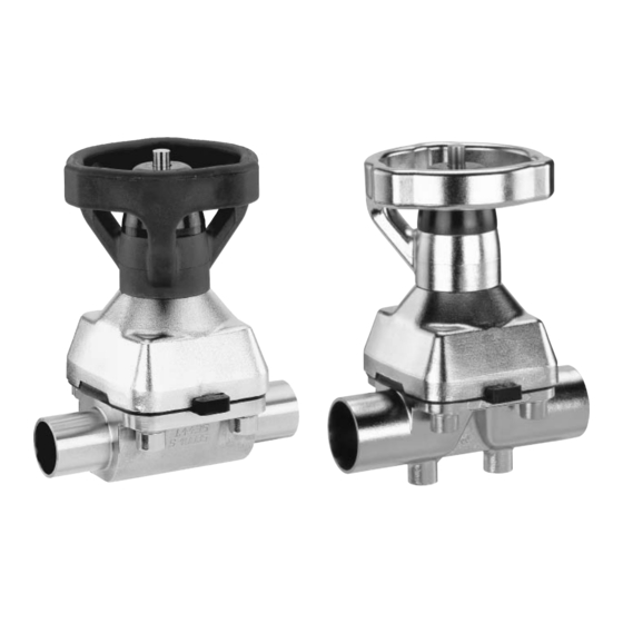
Manufacturer’s information with a stainless steel bonnet. GEMÜ 653 has a handwheel in high temperature and chemically resistant plastic, GEMÜ 654 a Transport stainless steel handwheel. The handwheels for diaphragm size 8 are rising, those for Only transport the diaphragm valve by diaphragm sizes 10-100 are non-rising. -
Page 10: Installation And Operation
3. Allow butt weld spigots to cool down. Installation work must only be performed 4. Reassemble the valve body and the by trained personnel. bonnet with diaphragm (see chapter Use appropriate protective gear as 12.4). specified in plant operator's guidelines. 653, 654 10 / 28... -
Page 11: Operation
Valve open Valve closed of delivery. 5. Use all flange holes. Max. permissible operating torques: 6. Only use connector elements made of approved materials! Diaphragm size 7. Tighten the bolts diagonally! Observe appropriate regulations for connections! 653, 654 11 / 28... -
Page 12: Setting The Seal Adjuster And The Stroke Limiter
Important: The threaded spindle 15 must GEMÜ 654 bonnet size 0TH not turn during this process! Diaphragm size 8 If necessary, hold with a SW8 open-end wrench! Fix the stroke limiting sleeve 5 with locking screw 9 (SW2 Allen key). - Page 13 Press protective cap a down. Turn seal adjuster c anticlockwise upwards until it stops. Setting the stroke limiter Move the bonnet to the desired OPEN position by turning the handwheel. 653, 654 13 / 28...
- Page 14 Releasing the seal adjuster Turn seal adjuster c clockwise Turn the stroke limiter clockwise downwards until it stops. downwards until it stops using the supplied setting tool b. Important: The seal adjuster must not turn during this process. 653, 654 14 / 28...
-
Page 15: Assembly / Disassembly Of Spare Parts
Important: After disassembly, clean all parts of contamination (do not damage parts). Check parts for potential damage, replace if necessary (only use genuine parts from GEMÜ). 12.2 Removing the diaphragm Important: Completing the settings Before removing the diaphragm, Put protective cap a in place and align the please remove the bonnet, see flats by a light twisting movement. - Page 16 C. Place the compressor loosely on the bonnet spindle, fit the recesses D into the guides C and A into B. The compressor must be able to be moved freely between the guides! 653, 654 16 / 28...
- Page 17 C. Place the compressor loosely on the bonnet spindle, fit the recesses D into the guides C and A into B. The compressor must be able to be moved freely between the guides! 653, 654 17 / 28...
-
Page 18: Mounting A Concave Diaphragm
(only use recess of the compressor. genuine parts from GEMÜ). 3. Turn the diaphragm as manual force 7. When clear resistance is felt turn back is applied to push the spigot into the the diaphragm anticlockwise until its bolt compressor. -
Page 19: Mounting A Convex Diaphragm
8. If it is difficult to screw it in, check the thread, replace damaged parts. 9. When clear resistance is felt turn back the diaphragm anticlockwise until its bolt holes are in correct alignment with the bolt holes of the bonnet. 653, 654 19 / 28... -
Page 20: Special Versions
13 Special versions 13.2 Special version with mechanical locking device A special version of GEMÜ 653 / 654 is 13.1 Special version with available with a mechanical locking device. electrical locking device With additional functions B, K, F (types of locking device) the locking device can be Special version of GEMÜ... -
Page 21: Special Version For Mounting Of Proximity Switches
Only use proximity switches that can be mounted flush. Delivery condition A special version of GEMÜ 653 / 654 is available for mounting of proximity switches (additional function A, see type key). Proximity switches can also be mounted in combination with additional functions B, K, F (see type key). - Page 22 • Screw in threaded plug 1. Setting the damping cam Screw in proximity switch 6 until it touches damping cam 3. Turn back proximity switch 6 by 1/2 to 3/4 turns. Secure this position by fixing it with nut X. 653, 654 22 / 28...
-
Page 23: Commissioning
(water hammer). by improper handling or third-party actions. Prior to cleaning or commissioning the In case of doubt, contact GEMÜ before plant: commissioning. Check the tightness and the function of the diaphragm valve (close and reopen 1. -
Page 24: Disassembly
Clean the valve. Request a goods return declaration form from GEMÜ. Returns must be made with a completed declaration of return. If not completed, GEMÜ cannot process credits or repair work but will dispose of the goods at the operator's expense. -
Page 25: Fault Clearance
See chapter 15. Proximity switch Wrong proximity switch used Only use proximity switch that can be mounted flush continuously responds * see chapter 21 "Sectional drawing and spare parts" 653, 654 25 / 28... -
Page 26: Sectional Drawing
21 Sectional drawing and spare parts Leak detection hole Item Name Order description Valve body K600... Diaphragm 600...M Bolt 653...S30... Washer 654...S30... 9653... Bonnet 9654... 653, 654 26 / 28... -
Page 27: 22 Ec Declaration Of Conformity
22 EC Declaration of Conformity Declaration of Conformity According to annex VII of the Directive 97/23/EC Hereby we, GEMÜ Gebr. Müller GmbH & Co. KG Fritz-Müller-Straße 6-8 D-74653 Ingelfingen declare that the equipment listed below complies with the safety requirements of the Pressure Equipment Directive 97/23/EC. - Page 28 VALVES, MEASUREMENT AND CONTROL SYSTEMS GEMÜ Gebr. Müller Apparatebau GmbH & Co. KG · Fritz-Müller-Str. 6-8 · D-74653 Ingelfi ngen-Criesbach Telefon +49(0)7940/123-0 · Telefax +49(0)7940/123-224 · info@gemue.de · www.gemu-group.com...