Table of Contents
Advertisement
Quick Links
INSTALLER: Leave this manual with party responsible for use and operation.
OWNER: Retain this manual for future reference.
NOTICE: DO NOT discard this manual!
Models:
This appliance may be installed as an OEM
installation in manufactured home (USA
only) or mobile home and must be installed
in accordance with the manufacturer's
instructions and the Manufactured Home
Construction and Safety Standard, Title 24
CFR, Part 3280 in the United States, or the
Standard for Installation in Mobile Homes,
CAN/CSA Z240 MH Series, in Canada.
This appliance is only for use with the type(s)
of gas indicated on the rating plate. This
appliance is not convertible for use with other
gases, unless a certified kit is used.
Installation Manual
Installation and Appliance Setup
Heat & Glo • ST-36TR-IFT, PIER-36TR-IFT Installation Manual • 2482-980 Rev. D • 3/19
WARNING:
FIRE OR EXPLOSION HAZARD
Failure to follow safety warnings exactly
could result in serious injury, death, or
property damage.
• DO NOT store or use gasoline or other flam-
mable vapors and liquids in the vicinity of this
or any other appliance.
• What to do if you smell gas
- DO NOT try to light any appliance.
- DO NOT touch any electrical switch. DO
NOT use any phone in your building.
- Leave the building immediately.
- Immediately call your gas supplier from
a neighbor's phone. Follow the gas sup-
plier's instructions.
- If you cannot reach your gas supplier, call
the fire department.
• Installation and service must be performed
by a qualified installer, service agency, or the
gas supplier.
DANGER
DO NOT TOUCH GLASS
NEVER ALLOW CHILDREN
A barrier designed to reduce the risk of
burns from the hot viewing glass is provided
with this appliance and shall be installed for
the protection of children and other at-risk
individuals.
In the Commonwealth of Massachusetts installation must be
performed by a licensed plumber or gas fitter.
See Table of Contents for location of additional Commonwealth
of Massachusetts requirements.
HOT GLASS WILL
CAUSE BURNS.
UNTIL COOLED.
TO TOUCH GLASS.
1
Advertisement
Table of Contents

Related Manuals for Heat & Glo PIER-36TR-IFT


Summary of Contents for Heat & Glo PIER-36TR-IFT
- Page 1 See Table of Contents for location of additional Commonwealth gases, unless a certified kit is used. of Massachusetts requirements. Heat & Glo • ST-36TR-IFT, PIER-36TR-IFT Installation Manual • 2482-980 Rev. D • 3/19...
-
Page 2: Table Of Contents
B. Securing and Leveling the Appliance ....39 C. Non-Combustible Material Installation ....40 = Contains updated information. Heat & Glo • ST-36TR-IFT, PIER-36TR-IFT Installation Manual • 2482-980 Rev. D • 3/19... -
Page 3: Installation Standard Work Checklist
_________________________________________________________________________________________________ _________________________________________________________________________________________________ Comments Communicated to party responsible ____________________ by ______________________on ___________ (Builder / Gen. Contractor/) (Installer) (Date) = Contains updated information. 2482-982 Rev. B 3/18 Heat & Glo • ST-36TR-IFT, PIER-36TR-IFT Installation Manual • 2482-980 Rev. D • 3/19... -
Page 4: Product Specific And Important Safety Information
State of California to cause cancer and (Propane) reproductive harm. For more information go to: www. PIER-36TR-IFT 38,000 21,000 P65Warnings.ca.gov. (0-2000 FT) (NG) PIER-36TR-IFT 35,500 20,000 (0-2000 FT) (Propane) Heat & Glo • ST-36TR-IFT, PIER-36TR-IFT Installation Manual • 2482-980 Rev. D • 3/19... -
Page 5: Requirements For The Commonwealth Of Massachusetts
VENT DIRECTLY BELOW. KEEP CLEAR OF ALL OB- of the installation. STRUCTIONS”. See Gas Connection section for additional Common- wealth of Massachusetts requirements. Heat & Glo • ST-36TR-IFT, PIER-36TR-IFT Installation Manual • 2482-980 Rev. D • 3/19... -
Page 6: Getting Started
Non-corrosive leak check solution 1/2 - 3/4 in. length, #6 or #8 Self-drilling screws Caulking material (300ºF minimum continuous exposure rating) One 1/4 in. female connection (for optional fan). Heat & Glo • ST-36TR-IFT, PIER-36TR-IFT Installation Manual • 2482-980 Rev. D • 3/19... -
Page 7: Inspect Appliance And Components
Call a qualified service technician to inspect the appliance and to replace any part of the control system and/or gas control which has been under water. Heat & Glo • ST-36TR-IFT, PIER-36TR-IFT Installation Manual • 2482-980 Rev. D • 3/19... -
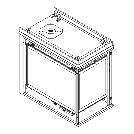
Page 8: Framing And Clearances
RIGHT VIEW LEFT VIEW Location Inches Millimeters Location Inches Millimeters 1-1/2 42-1/2 1080 24-1/2 33-1/2 9-1/2 2-1/8 34-5/8 4-1/8 4-1/4 38-1/8 Figure 3.1 Appliance Dimensions - ST-36TR-IFT Heat & Glo • ST-36TR-IFT, PIER-36TR-IFT Installation Manual • 2482-980 Rev. D • 3/19... - Page 9 LEFT VIEW Location Inches Millimeters Location Inches Millimeters 1-1/2 37-1/8 40-1/2 1029 24-1/2 33-1/2 9-1/2 2-1/8 4-1/8 34-5/8 4-1/4 38-1/8 Figure 3.2 Appliance Dimensions - PIER-36TR-IFT Heat & Glo • ST-36TR-IFT, PIER-36TR-IFT Installation Manual • 2482-980 Rev. D • 3/19...
- Page 10 DECORATIVE FRONT - CHATEAU (Model: ST-36TR-IFT, PIER-36TR-IFT) CHA-36 Location Inches Millimeters 32-7/16 20-1/2 37-1/16 1-3/16 7-13-16 32-7/8 34-1/16 Figure 3.3 Decorative Front Dimensions - ARCADIA and CHATEAU Heat & Glo • ST-36TR-IFT, PIER-36TR-IFT Installation Manual • 2482-980 Rev. D • 3/19...
- Page 11 DECORATIVE FRONT - HALSTON (Model: ST-36TR-IFT) HAL-36 Location Inches Millimeters 32-7/16 21-1/4 37-1/16 1-3/16 7-3/8 32-7/8 34-1/16 Figure 3.4 Decorative Front Dimensions - FOLIO and HALSTON Heat & Glo • ST-36TR-IFT, PIER-36TR-IFT Installation Manual • 2482-980 Rev. D • 3/19...
- Page 12 Figure 3.5 Decorative Front Dimensions - GALLERIA END PANEL - EP-ARC36 (Model: PIER-36TR-IFT) EP-ARC36 Location Inches Millimeters 20-1/8 23-3/8 26-11/16 1-3/8 7-13/16 32-1/16 33-7/16 Figure 3.6 End Panel Dimensions - EP-ARC36 Heat & Glo • ST-36TR-IFT, PIER-36TR-IFT Installation Manual • 2482-980 Rev. D • 3/19...
- Page 13 END PANEL - EP-FOL36 (Model: PIER-36TR-IFT) EP-FOL36 Location Inches Millimeters 20-1/8 23-3/8 26-11/16 1-3/8 7-13/16 32-1/16 33-7/16 Figure 3.7 End Panel Dimensions - EP-CHA36 and EP-FOL36 Heat & Glo • ST-36TR-IFT, PIER-36TR-IFT Installation Manual • 2482-980 Rev. D • 3/19...
-
Page 14: Clearances To Combustibles
36 in. 36 in. 914 mm 914 mm PIER-36TR-IFT 36 in. 914 mm 36 in. 914 mm ST-36TR-IFT 36 in. 914 mm Figure 3.8 Appliance Locations Heat & Glo • ST-36TR-IFT, PIER-36TR-IFT Installation Manual • 2482-980 Rev. D • 3/19... - Page 15 Opening (Height) (Depth) (Width) (Width) (Width) Inches 38-1/8 Millimeters 1092 Adjust framing dimensions for interior sheathing (such as sheetrock) Figure 3.9 Clearances to Combustibles - ST-36TR-IFT Heat & Glo • ST-36TR-IFT, PIER-36TR-IFT Installation Manual • 2482-980 Rev. D • 3/19...
- Page 16 Opening (Height) (Depth) (Width) (Width) (Width) Inches 38-1/8 Millimeters 1016 Adjust framing dimensions for interior sheathing (such as sheetrock) Figure 3.10 Clearances to Combustibles - PIER-36TR-IFT Heat & Glo • ST-36TR-IFT, PIER-36TR-IFT Installation Manual • 2482-980 Rev. D • 3/19...
-
Page 17: Constructing The Appliance Chase
• The chase must be properly blocked to prevent blown insulation or other combustibles from entering and making contact with fireplace or chimney. • Failure to maintain airspace may cause overheating and a fire. Heat & Glo • ST-36TR-IFT, PIER-36TR-IFT Installation Manual • 2482-980 Rev. D • 3/19... -
Page 18: Termination Location And Vent Information
Over 20/12 to 21/12 ..........8.0 * H minimum may vary depending on regional snowfall. Refer to local codes. Figure 4.1 Minimum Height From Roof to Lowest Discharge Opening Heat & Glo • ST-36TR-IFT, PIER-36TR-IFT Installation Manual • 2482-980 Rev. D • 3/19... -
Page 19: Chimney Diagram
2 sides beneath the floor. venting system does not meet these requirements. • Vinyl protection kits are suggested for use with vinyl siding. Figure 4.3 Minimum Clearances for Termination Heat & Glo • ST-36TR-IFT, PIER-36TR-IFT Installation Manual • 2482-980 Rev. D • 3/19... -
Page 20: Approved Pipe
WARNING! Risk of Fire or Asphyxiation. This appli- ance requires a separate vent. DO NOT vent to a pipe serving a separate solid fuel burning appliance. Heat & Glo • ST-36TR-IFT, PIER-36TR-IFT Installation Manual • 2482-980 Rev. D • 3/19... -
Page 21: Use Of Elbows
8-1/2 DVP24 DVP36 25-1/2 DVP48 1219 DVP6A 3 to 6 76 to 152 2-1/8-4-1/4 54-108 DVP12A 3 to 12 76 to 305 2-1/8-8-1/2 54-216 Figure 4.4 Heat & Glo • ST-36TR-IFT, PIER-36TR-IFT Installation Manual • 2482-980 Rev. D • 3/19... -
Page 22: Measuring Standards
Note: Reference Figure 4.21 for special instructions for use of 45º elbow on rear vent appliances. Figure 4.7. Measure to Top of Last Section of Pipe Figure 4.8 Heat & Glo • ST-36TR-IFT, PIER-36TR-IFT Installation Manual • 2482-980 Rev. D • 3/19... - Page 23 60 ft (18.3 m) max. 2 ft. SLP (305 mm) 4 ft. SLP DVP-SLP24 Adapter DVP-2SL Figure 4.9 Adapt DVP Pipe to SLP Using DVP-SLP24 & DVP-2SL Heat & Glo • ST-36TR-IFT, PIER-36TR-IFT Installation Manual • 2482-980 Rev. D • 3/19...
- Page 24 4.6 m 6 ft. 1.8 m 18 ft. 5.5 m = 50 ft. (15.2 m) Maximum = 18 ft. (5.5 m) Maximum INSTALLED HORIZONTALLY Figure 4.11 Heat & Glo • ST-36TR-IFT, PIER-36TR-IFT Installation Manual • 2482-980 Rev. D • 3/19...
- Page 25 3 ft. 914 mm 12 ft.* 3.7 m 6 ft 1.8 m = 18 ft. (5.5 m) Maximum = 50 ft. (15.2 m) Maximum Figure 4.12 Heat & Glo • ST-36TR-IFT, PIER-36TR-IFT Installation Manual • 2482-980 Rev. D • 3/19...
- Page 26 6 ft. 1.8 m 6 ft. 1.8 m = 50 ft. (15.2 m) Maximum = 18 ft. (5.5 m) Maximum Installed Vertically Installed Horizontally Figure 4.13 Heat & Glo • ST-36TR-IFT, PIER-36TR-IFT Installation Manual • 2482-980 Rev. D • 3/19...
- Page 27 10-60 feet, an exhaust restrictor may panel after exhaust be needed. The exhaust restrictor can be located in the restrictor installation. appliance manual bag. Figure 4.15 Heat & Glo • ST-36TR-IFT, PIER-36TR-IFT Installation Manual • 2482-980 Rev. D • 3/19...
- Page 28 MUST subtract one number from the table above. Example: Top vent 60 ft vertical with DVP pipe = 3-3 Top vent 60 ft vertical with SLP pipe = 2-2 Heat & Glo • ST-36TR-IFT, PIER-36TR-IFT Installation Manual • 2482-980 Rev. D • 3/19...
- Page 29 1.8 m 18 ft. 5.5 m = 50 ft (15.2 m) Maximum *No specific restrictions on this value EXCEPT cannot exceed 50 ft (15.2 m) Figure 4.18 Heat & Glo • ST-36TR-IFT, PIER-36TR-IFT Installation Manual • 2482-980 Rev. D • 3/19...
- Page 30 18 ft. 5.5 m = 18 ft (5.5 m) Maximum *No specific restrictions on this value EXCEPT cannot exceed 50 ft (15.2 m) INSTALLED HORIZONTALLY Figure 4.19 Heat & Glo • ST-36TR-IFT, PIER-36TR-IFT Installation Manual • 2482-980 Rev. D • 3/19...
- Page 31 = 16 in. (406 mm) Maximum No Elbow Figure 4.20 One 45º Elbow DO NOT use a 45º elbow in corner installations. Use two 90º elbow instead. Figure 4.21 Heat & Glo • ST-36TR-IFT, PIER-36TR-IFT Installation Manual • 2482-980 Rev. D • 3/19...
- Page 32 1.2 m 8 ft. 2.4 m = 40 ft (12.2 m) Maximum = 3 ft (94 mm) Maximum = 12 ft (3.7 m) Maximum Figure 4.23 Heat & Glo • ST-36TR-IFT, PIER-36TR-IFT Installation Manual • 2482-980 Rev. D • 3/19...
- Page 33 10 ft. 6 ft. 1.8 m 12 ft. 3.7 m = 50 ft (15.2 m) Maximum = 16 ft (4.9 m) Maximum INSTALLED HORIZONTALLY Figure 4.25 Heat & Glo • ST-36TR-IFT, PIER-36TR-IFT Installation Manual • 2482-980 Rev. D • 3/19...
- Page 34 1.8 m *No specific restrictions on this value EXCEPT cannot exceed 50 ft. (15.2 m) Maximum = 6 ft. (1.8 m) Maximum INSTALLED HORIZONTALLY Figure 4.27 Heat & Glo • ST-36TR-IFT, PIER-36TR-IFT Installation Manual • 2482-980 Rev. D • 3/19...
-
Page 35: Vent Clearances And Framing
* Shows center of vent framing hole for top or rear venting. The center of the hole is one (1) inch (25.4 mm) above the center of the horizontal vent pipe. Figure 5.2 Wall Penetration Heat & Glo • ST-36TR-IFT, PIER-36TR-IFT Installation Manual • 2482-980 Rev. D • 3/19... -
Page 36: Ceiling Firestop/Floor Penetration Framing
INSTALL ATTIC INSULATION SHIELDS BEFORE OR AFTER INSTALLATION OF VENT SYSTEM CEILING FIRESTOP CEILING FIRESTOP INSTALLED BELOW CEILING INSTALLED ABOVE CEILING Figure 5.4 Installing the Attic Shield Heat & Glo • ST-36TR-IFT, PIER-36TR-IFT Installation Manual • 2482-980 Rev. D • 3/19... -
Page 37: Appliance Preparation
Secure the vent gasket to the appliance with two self-tapping screws found in the manual bag. Note: The vent gasket can found in the manual bag. Proceed to Section 6.B. Heat & Glo • ST-36TR-IFT, PIER-36TR-IFT Installation Manual • 2482-980 Rev. D • 3/19... - Page 38 Secure the vent gasket to the appliance with two self-tapping screws found in the manual bag. Note: The vent gasket can found in the manual bag. Heat & Glo • ST-36TR-IFT, PIER-36TR-IFT Installation Manual • 2482-980 Rev. D • 3/19...
-
Page 39: Securing And Leveling The Appliance
Note: Diagonal dimensions (A) and (B) must be within 1/4 inch of each other. Figure 6.12 Positioning the Appliance Squarely 90º Figure 6.10 Proper Positioning and Leveling of an Appliance Heat & Glo • ST-36TR-IFT, PIER-36TR-IFT Installation Manual • 2482-980 Rev. D • 3/19... -
Page 40: Non-Combustible Material Installation
This board must be used. See Figure 6.13. WARNING! Risk of Fire! DO NOT remove factory- installed non-combustible material. NON-COMBUSTIBLE BOARD Figure 6.13 Non-combustible Board Heat & Glo • ST-36TR-IFT, PIER-36TR-IFT Installation Manual • 2482-980 Rev. D • 3/19... -
Page 41: Venting And Chimneys
If predrilling holes, DO NOT penetrate inner pipe. INCORRECT Figure 7.4 Seams For 90º and 45º elbows that are changing the vent direction Heat & Glo • ST-36TR-IFT, PIER-36TR-IFT Installation Manual • 2482-980 Rev. D • 3/19... -
Page 42: Assemble Vent Sections
• Only outer pipes need to be sealed. All unit collar, pipe, slip section, elbow and cap outer flues shall be sealed in this manner, unless otherwise stated. Heat & Glo • ST-36TR-IFT, PIER-36TR-IFT Installation Manual • 2482-980 Rev. D • 3/19... -
Page 43: Assemble Slip Sections (Slp & Dvp)
• Only outer pipes are sealed, sealing the inner flue is not required. • All unit collar, pipe, slip section, elbow and cap outer flues shall be sealed. Heat & Glo • ST-36TR-IFT, PIER-36TR-IFT Installation Manual • 2482-980 Rev. D • 3/19... -
Page 44: Disassemble Vent Sections
Figure 7.11. • Pull carefully to separate the pieces of pipe. Figure 7.10 Rotate Seams for Disassembly Figure 7.11 Align and Disassemble Vent Sections Heat & Glo • ST-36TR-IFT, PIER-36TR-IFT Installation Manual • 2482-980 Rev. D • 3/19... -
Page 45: Vertical Termination Requirements
• Caulk the perimeter of the flashing where it contacts the roof surface. See Figure 7.13. • Caulk the overlap seam of any exposed pipe sections that are located above the roof line. Heat & Glo • ST-36TR-IFT, PIER-36TR-IFT Installation Manual • 2482-980 Rev. D • 3/19... -
Page 46: Horizontal Termination Requirements
• Rest the small leg on the extended heat shield on top of the pipe section to properly space it from the pipe section. Figure 7.15 Important Notice: Heat shields may not be fi eld constructed. Heat & Glo • ST-36TR-IFT, PIER-36TR-IFT Installation Manual • 2482-980 Rev. D • 3/19... - Page 47 DVP-TRAP1 can adjust 1-1/2 in. (3-1/8 to 4-5/8 in.) DVP-TRAP2 can adjust 4 in. (5-3/8 to 9-3/8) DVP-HPC1 can adjust 2-1/8 in. (4-1/4 to 6-3/8) DVP-HPC2 can adjust 4-1/8 in. (6-3/8 to 10-1/2) Heat & Glo • ST-36TR-IFT, PIER-36TR-IFT Installation Manual • 2482-980 Rev. D • 3/19...
-
Page 48: Electrical Information
ROMEX CONNECTORS NOTICE: DO NOT wire 110-120 VAC to wall switch. Figure 8.1 Junction Box Detail Heat & Glo • ST-36TR-IFT, PIER-36TR-IFT Installation Manual • 2482-980 Rev. D • 3/19... -
Page 49: Intellifire™ Touch Ignition System Wiring
Do not store batteries in the battery pack when the appliance is powered by the 6 volt transformer connected to permanent electrical service. Heat & Glo • ST-36TR-IFT, PIER-36TR-IFT Installation Manual • 2482-980 Rev. D • 3/19... - Page 50 EMBER LIGHT CONNECTOR BLOCK 2482-019 ORANGE GROUND TO FIREPLACE CHASSIS GREEN BULB SOCKET ASSEMBLY (3) 2005-188 HALOGEN BULBS 700-542 Figure 8.2 IntelliFire Touch Wiring With Remote Heat & Glo • ST-36TR-IFT, PIER-36TR-IFT Installation Manual • 2482-980 Rev. D • 3/19...
- Page 51 2155-033 PVI-WH20 PVI-WH40 PVI-WH60 ORANGE PVI-WH80 PVI-WH100 GROUND TO FIREPLACE PVI-SLP-B OR PVLP-SLP CHASSIS GREEN PVLP-SLP PVI-SLP-B Figure 8.3 IntelliFire Touch Wiring With Optional Power Vent Heat & Glo • ST-36TR-IFT, PIER-36TR-IFT Installation Manual • 2482-980 Rev. D • 3/19...
-
Page 52: Fan (Optional)
• Connect temperature sensor switch wire and rheostat switch to junction box as shown in Figure 8.5. RHEOSTAT JUNCTION BOX SWITCH TEMPERATURE SENSOR BLUE Figure 8.5 Detail of Fan Wiring with Rheostat Heat & Glo • ST-36TR-IFT, PIER-36TR-IFT Installation Manual • 2482-980 Rev. D • 3/19... -
Page 53: Gas Information
4500 feet (1370 m). • If substituting for these components, please consult local codes for compliance. Check with your local gas utility to determine proper orifice size. Heat & Glo • ST-36TR-IFT, PIER-36TR-IFT Installation Manual • 2482-980 Rev. D • 3/19... -
Page 54: Air Shutter Setting
Maximum” shown in Figure 4.20. Note: All vent runs may need to be evaluated for ideal shutter settings. Shutter distances may vary due to vent run, fuel quality, and elevation. Heat & Glo • ST-36TR-IFT, PIER-36TR-IFT Installation Manual • 2482-980 Rev. D • 3/19... -
Page 55: Finishing
0 in. 0 in. 0 in. High Temperature Sealant (300° F/149° C min.) Top and Side Seal Joint = Factory-Installed Non-Combustible Board Figure 10.1 Non-combustible Facing Diagram Heat & Glo • ST-36TR-IFT, PIER-36TR-IFT Installation Manual • 2482-980 Rev. D • 3/19... -
Page 56: Mantel And Wall Projections
Figure 10.5 Minimum Vertical and Maximum Horizontal Dimensions of Non-Combustibles MEASUREMENT FROM FIREPLACE OPENING TO BOTTOM OF APPLIANCE= 33-1/2 IN. Figure 10.3 Minimum Vertical and Maximum Horizontal Dimensions of Combustibles Heat & Glo • ST-36TR-IFT, PIER-36TR-IFT Installation Manual • 2482-980 Rev. D • 3/19... -
Page 57: Finishing Material
1 in. MAX DOOR FINISHING MATERIAL (TOP EDGE) Finishing materials 1 inch maximum thick. Stop finishing material flush with opening. Figure 10.9 Overlap Fit Decorative Front Heat & Glo • ST-36TR-IFT, PIER-36TR-IFT Installation Manual • 2482-980 Rev. D • 3/19... - Page 58 2 IN., DOORS WILL ONLY OPEN AS FAR AS PICTURED DOORS 37-1/2 IN. Finishing material between 1 and 2 inches thick. Figure 10.11 Operable Hinge Decorative Front Heat & Glo • ST-36TR-IFT, PIER-36TR-IFT Installation Manual • 2482-980 Rev. D • 3/19...
-
Page 59: Appliance Setup
Step 2. Crease flap on top side of splatter guard using GLASS ASSEMBLY the scored line as the guide. See Figure 11.3. Figure 11.1 Fixed Glass Assembly Figure 11.3 Heat & Glo • ST-36TR-IFT, PIER-36TR-IFT Installation Manual • 2482-980 Rev. D • 3/19... - Page 60 See Figure 11.10. Figure 11.5 Installation of Splatter Guard TOP SLOT Figure 11.6 Top slot Figure 11.9 Opening Lower Access Panel Heat & Glo • ST-36TR-IFT, PIER-36TR-IFT Installation Manual • 2482-980 Rev. D • 3/19...
-
Page 61: Clean The Appliance
Carefully grab splatter guard on or near the vertical cen- ter on the left and right sides. Pull outward gently, but firmly, taking care not to tear or remove the inserted tabs. Heat & Glo • ST-36TR-IFT, PIER-36TR-IFT Installation Manual • 2482-980 Rev. D • 3/19... -
Page 62: Lava Rock/Teco-Sil And Glowing Ember Placement
Figure 11.15. Make sure to paint the glass ember rock from both sides as shown in Figure 11.18. Figure 11.15 Teco-Sil Placement Figure 11.18 Painting Teco-Sil Heat & Glo • ST-36TR-IFT, PIER-36TR-IFT Installation Manual • 2482-980 Rev. D • 3/19... - Page 63 • Save the remaining ember materials for use during appliance servicing. The embers provided should be enough for 3 to 5 applications. Figure 11.19 Placement of Embers Heat & Glo • ST-36TR-IFT, PIER-36TR-IFT Installation Manual • 2482-980 Rev. D • 3/19...
-
Page 64: Install The Log Assembly
LOG #2 (SRV2005-700): Position log #2 on the left grate bar and the pilot assembly. Use the cut out notches on the log to position it as shown. Heat & Glo • ST-36TR-IFT, PIER-36TR-IFT Installation Manual • 2482-980 Rev. D • 3/19... - Page 65 LOG #5 (SRV2005-704): Using the sharp notch on the heavy end of log #5, align it on the grate tine and set it on the flat area of log #4 as shown. Heat & Glo • ST-36TR-IFT, PIER-36TR-IFT Installation Manual • 2482-980 Rev. D • 3/19...
- Page 66 #1. The orientation of log #6 in relation to the grate tine is shown below. Notch engaged with grate tine. Log Assembly Installed. Heat & Glo • ST-36TR-IFT, PIER-36TR-IFT Installation Manual • 2482-980 Rev. D • 3/19...
-
Page 67: Intellifire™ Touch Control System Setup
5. Wait to verify LED indicator on the ECM stops flash- ing. 6. Install batteries in the RC400 remote. 7. The RC400 remote will automatically pair to the appli- ance as pre-set at the factory. Heat & Glo • ST-36TR-IFT, PIER-36TR-IFT Installation Manual • 2482-980 Rev. D • 3/19... -
Page 68: Reference Materials
6 in. (152 mm) 14 IN. (356 MM) 12 IN. (305 MM) DVP-WS (Wall Shield Firestop) DVP-RDS ROOF DECK INSULATION SHIELD Figure 12.1 DVP Vent Components Heat & Glo • ST-36TR-IFT, PIER-36TR-IFT Installation Manual • 2482-980 Rev. D • 3/19... - Page 69 117 mm Length DVP-TRAP 5-3/8 in. 9-3/8 in. Trap2 Horizontal Termination Cap 137 mm 238 mm DVP-TRAP2 DVP-TRAP1 DVP-TRAPK2 DVP-TRAPK1 DVP-HPC2 DVP-HPC1 Figure 12.2 DVP Vent Components Heat & Glo • ST-36TR-IFT, PIER-36TR-IFT Installation Manual • 2482-980 Rev. D • 3/19...
- Page 70 9-1/2 in. (352 mm) (241 mm) 26 in. 660 mm 14 in. (356 mm) DVP-HSM-B DRC-RADIUS Extended Heat Shield Cap Shield Figure 12.3 DVP Vent Components Heat & Glo • ST-36TR-IFT, PIER-36TR-IFT Installation Manual • 2482-980 Rev. D • 3/19...
- Page 71 1 in. (25 mm) 7-3/4 to 10-3/8 in. 1-5/8 in. (197 to 264 mm) (41 mm) DVP-FBHT DVP-HPC FireBrickTermination Cap High Performance Cap Figure 12.4 DVP Vent Components Heat & Glo • ST-36TR-IFT, PIER-36TR-IFT Installation Manual • 2482-980 Rev. D • 3/19...
- Page 72 213 mm 146 to 213 mm 3° 87° 15 in. (381 mm) 10-1/2 in. 267 mm 10-7/8 in. 276 mm DVP-HRC-SS DVP-HRC-ZC-SS Figure 12.5 Vent Components Heat & Glo • ST-36TR-IFT, PIER-36TR-IFT Installation Manual • 2482-980 Rev. D • 3/19...
- Page 73 13-5/8 IN. 16-11/16 IN. 16-11/16 IN. (346 mm) 424 mm (424 mm) 12-1/2 IN. SLP-LPC (318 mm) SLP Low Profile Cap Figure 12.6 PVI-SLP-B Vent Components Heat & Glo • ST-36TR-IFT, PIER-36TR-IFT Installation Manual • 2482-980 Rev. D • 3/19...
- Page 74 60 FT PV Wire Harness PVI-WH60 80 FT PV Wire Harness PVI-WH80 100 FT PV Wire Harness PVI-WH100 PVLP-BEK PVLP-HS Brick Kit Heat Shield Figure 12.7 PVLP-SLP Vent Components Heat & Glo • ST-36TR-IFT, PIER-36TR-IFT Installation Manual • 2482-980 Rev. D • 3/19...
- Page 75 1-1/2 in. 5-1/2 in. 12 in. 220 mm 38 mm 305 mm 146 mm SLP-WS SLP-FS Wall Shield Firestop Ceiling Firestop Figure 12.8 SLP Series Vent Components Heat & Glo • ST-36TR-IFT, PIER-36TR-IFT Installation Manual • 2482-980 Rev. D • 3/19...
- Page 76 12-5/8 IN. 10-5/8 IN. 59 mm 367 mm (321 mm) (270 mm) SLP-RDS SLP-WT-BK ROOF DECK INSULATION SHIELD Wall Thimble-Black Figure 12.9 SLP Series Vent Components Heat & Glo • ST-36TR-IFT, PIER-36TR-IFT Installation Manual • 2482-980 Rev. D • 3/19...
- Page 77 343 mm 121 mm 7-3/4 to 10-3/8 in. (197 to 264 mm) DVP-FBHT SLK-SNKD Horizontal Snorkel Termination Cap Termination Cap Figure 12.10 SLP Series Vent Components Heat & Glo • ST-36TR-IFT, PIER-36TR-IFT Installation Manual • 2482-980 Rev. D • 3/19...
- Page 78 8 IN. (203 mm) 15 IN. (381 mm) 12 IN. (305 mm) SLP-HHW2 Horizontal High Wind Termination Cap Figure 12.11 SLP Series Vent Components Heat & Glo • ST-36TR-IFT, PIER-36TR-IFT Installation Manual • 2482-980 Rev. D • 3/19...
-
Page 79: Accessories
Please contact your Heat & Glo dealer with any questions or concerns. For the location of your nearest Heat & Glo dealer, please visit www.heatnglo.com. Printed in U.S.A. - Copyright 2019 Heat & Glo • ST-36TR-IFT, PIER-36TR-IFT Installation Manual • 2482-980 Rev. D • 3/19...