Table of Contents
Advertisement
Quick Links
Installation - Parts
®
E-Flo
Electric Pumps
for Sealants and Adhesives
For use with single-component sealant and adhesive materials. For professional use only.
Not approved for use in explosive atmospheres or hazardous locations.
See page 3 for model information, including maximum working pressure and approvals.
Important Safety Instructions
Read all warnings and instructions in this
manual and in all related manuals before
using the equipment. Save all instruc-
tions.
EC100CS2
SP
ED145SS2
3A6586A
EN
ED145CS2
Advertisement
Table of Contents

Related Manuals for Graco E-Flo SP EC100CS2


Summary of Contents for Graco E-Flo SP EC100CS2
- Page 1 Installation - Parts ® E-Flo Electric Pumps 3A6586A for Sealants and Adhesives For use with single-component sealant and adhesive materials. For professional use only. Not approved for use in explosive atmospheres or hazardous locations. See page 3 for model information, including maximum working pressure and approvals. Important Safety Instructions Read all warnings and instructions in this manual and in all related manuals before...
-
Page 2: Table Of Contents
Shutdown and Care of the Pump ... . . 16 Graco Standard Warranty ....40 Driver Maintenance . -
Page 3: Models
Models Models NOTE: Each Check-Mate pump size is available in CS, Check your pump package’s identification (ID) label located on the side of the electric driver for the 8-digit CM, SS, and SM pump materials. Dura-Flo pump mate- part number of your pump package. Use the following rial combinations depend on the pump size. -
Page 4: System Pressure
Models System Pressure Due to factors such as the dispensing system design, the material being pumped, and the flow rate, the dynamic pressure will not reach the rated working (stall) pressure of the system. Pump Working (Stall) Pressure Max Dynamic (Run) Pressure Lower Size 6,000 41.4... -
Page 5: Warnings
Warnings Warnings The following warnings are for the setup, use, grounding, maintenance, and repair of this equipment. The exclama- tion point symbol alerts you to a general warning and the hazard symbols refer to procedure-specific risks. When these symbols appear in the body of this manual or on warning labels, refer back to these Warnings. Product-specific hazard symbols and warnings not covered in this section may appear throughout the body of this manual where applicable. - Page 6 Warnings WARNING FIRE AND EXPLOSION HAZARD Flammable fumes, such as solvent and paint fumes, in work area can ignite or explode. Paint or solvent flowing through the equipment can cause static sparking. To help prevent fire and explosion: • Use equipment only in well-ventilated area. •...
-
Page 7: Component Identification
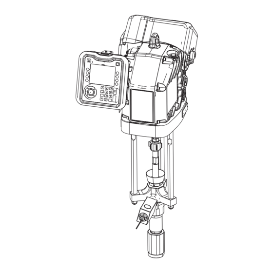
Component Identification Component Identification Electric Pump with 220 cc Dura-Flo CS Lower Model EC100xxx Only . 1: E-Flo SP Components Key: Electric Driver Wet Cup Displacement Pump Disconnect Switch Check Valve Block Driver Output Shaft Advanced Display Module (ADM) Fluid Hose Connection Lift Ring Pressure Transducer Sensor Power Junction Box... -
Page 8: Advanced Display Module (Adm)
Component Identification Advanced Display Module (ADM) Front and Rear Views . 2: ADM Component Identification Key: BA Pump Enable BG Lock/Setup Enables the pump. Toggles between Active and System Toggle between run and setup screens. BH Directional Keypad Off. BB Pump Status Indicator Light Navigate within a screen or to a new screen. -
Page 9: Installation
29 megaohms, replace the hose immediately. Dispense valve: ground through connection to a prop- Three pump mounting options are available from Graco: erly grounded fluid hose and pump. a pump stand, a wall mount, and a floor mount adpater. -
Page 10: Connect Power
Installation Connect Power NOTE: Inside the junction box, power wires to the driver are connected to terminals 3L2 and 5L3 on the discon- nect block. Refer to Figure 5 for the terminal locations. All electrical wiring must be done by a qualified elec- Incoming Power to trician and comply with all local codes and regula-... -
Page 11: Connect The Standalone Transformer
Installation Connect the Standalone NOTE: Do not attach the ground wire to the grounding lug locknut located by the wiring cord grip on the outside Transformer of the electric driver. The lug locknut should only be used for other grounding purposes if needed. 6. -
Page 12: Install Vented Oil Cap Before Using Equipment
Installation Install Vented Oil Cap Before 7. Connect wiring (not included) to X1 and X2 and a ground wire to the grounding bar. This wiring is for Using Equipment. connection to the pump. The driver gear-box is shipped from the factory pre-filled Connections to Pump with oil. -
Page 13: Connecting Multiple Pumps
Installation Connecting Multiple Pumps Up to six E-Flo SP pumps can be connected together 1. Connect a CAN cable from port 1 on the first pump (shown as Pump 1 in Figure 11) to the splitter. and operated from one Advanced Display Module (ADM). -
Page 14: Setup
NOTE: The pump is tested with lightweight oil, which is left in to protect the pump parts. If the fluid you are using Before starting, fill the wet cup (H) 1/3 full with Graco may be contaminated by the oil, flush it out with a com- Throat Seal Liquid (TSL) or a compatible solvent. - Page 15 Setup 4. Enter the Edit screen for that pump by pressing the soft key next to the icon. 5. Press the soft key next to the Pressure Mode icon. 6. Enter 100 psi (0.69 MPa, 6.9 bar) as the pressure. 7.
-
Page 16: Pressure Relief Procedure
Pressure Relief Procedure Pressure Relief 9. Open your system’s fluid line drain valve and open each pumps bleed valve (G). Have a container Procedure ready to catch the drainage. 10. Leave the pump bleed valves (G) open until ready to dispense again. -
Page 17: Driver Maintenance
If the oil is low, open the fill cap and add Graco Part No. 16W645 ISO 220 silicone-free synthetic EP Preventative Maintenance Schedule gear oil. -
Page 18: Parts
Parts Parts Electric Pumps with Check-Mate Lowers NOTE: These parts apply to all Check-Mate electric pump configurations. EC100CS2 Shown EC100xxx to EC250xxx Pumps Included with 480 VAC models only. 1f 2 Torque to 50-60 ft-lbs (68-81 N•m). Torque to 124-155 ft-lbs (168-210 N•m). Apply blue pipe sealant. - Page 19 Parts Parts List for EC100xxx, 200xxx, and 250xxx Ref Part Description Quantity PUMP, electrical, c-mate 1a 25N519 KIT, driver, apd20, vertical 1b 15K750 ROD, tie, nxt to cm lower 1c Table 1† LOWER, pump 1d 108098 WASHER, lock, spring 1e 106166 NUT, mach, hex 1f 15H392 ROD, adapter, extreme...
- Page 20 Parts Ref Part Description Quantity Electric Driver Warning Labels 16W360 LABEL, safety, warning, multiple 17J476 LABEL, safety, warning, multiple 195792 LABEL, safety, warning, electric shock 195793 LABEL, safety, warning, electric shock Pump Lower Warning Labels 184090 PLATE, warning 184462 PLATE, warning, sst 48 184151...
- Page 21 Parts EC500CSx EC500CMx EC500SSx EC500SMx Ref Part Description Quantity 1g 184129 COLLAR, coupling 1h 186925 NUT, coupling 1k 112887* TOOL, wrench, spanner 1m 25N739 VALVE, check, 1 1/2 in. npt 1p 17Y515 LABEL, e-flo sp 1r C38321* TIE, cable, 3.62 LG 24P823...
-
Page 22: Electric Pumps With Dura-Flo Lowers
Parts Electric Pumps with Dura-Flo Lowers NOTE: These parts apply to all Dura-Flo electric pump configurations. ED115CS2 Shown Included with 480 VAC models only. Torque to 50-60 ft-lbs (68-81 N•m). Torque to 90-100 ft-lbs (122-136 N•m). Apply blue pipe sealant. Apply tan lubricant. - Page 23 Parts Parts List for All EPDxxxxxx Models Ref Part Description Quantity PUMP, electrical, duraflo 1a 25N519 KIT, driver, apd20, vertical 15F837 ROD, tie, 14 1/4 long 15H562 ROD, tie 1c Table 4† LOWER, xtreme, 115, nf, xseal 1d 101712 NUT, lock 15H392 ROD, adapter xtreme 15H370...
- Page 24 Parts Ref Part Description Quantity 123970 SWITCH, disconnect, 40 a 123971 KNOB, disconnect, operator 130692 COVER, juction box, apd motor 113768 SCREW, socket, fl hd 16T764 LABEL, warning 25E268‡ KIT, transformer, stand alone Electric Driver Warning Labels 16W360 LABEL, safety, warning, multiple 17J476...
-
Page 25: Check Valves
Parts Check Valves Check Valve Block with Pressure Relief, 25N738 NOTE: For model EC100xxx only. Apply a light coating of anti-seize lubricant as needed. Torque to 30 +/- 2 ft-lbs (41 +/- 2 N•m). Apply blue sealant to threads as needed. Apply grease. - Page 26 Parts Check Valve Block, 1-1/2 Inch, 25N739 NOTE: For models EC500xxx and ED430xxx Apply a light coating of anti-seize lubricant as needed. . 17: 1-1/2 Inch Check Valve Part Description 19A566 BLOCK, check valve, 1-12 in. npt sst 17Y980 HOUSING, ball cage 1-1/2 in. npt check 104537...
- Page 27 Parts Check Valve Block, 1 Inch, 25N780 NOTE: For models EC200xxx, EC250xxx, ED115xxx, ED145xxx, ED180xxx, ED220xxx, ED290xxx 405 403 Apply a light coating of anti-seize lubricant as needed. . 18: 1 Inch Check Valve Part Description 19A615 BLOCK, check valve, 1 in. npt sst 15Y168 HOUSING, ball cage 107098...
-
Page 28: Kits And Accessories
Kits and Accessories Kits and Accessories Advanced Display Module Kit 25E439 . 19: ADM Kit Part Description 16T234 BRACKET, display, mount 24A326 BRACKET, mounting, assembly 16T935 FASTENER, knob 111307 WASHER, lock, external 117017 WASHER 117026 SCREW, shcs m5 x 12 121001* CABLE, can, female/female 1.0 m 24E451... -
Page 29: Communication Gateway Module (Cgm) Kits
Kits and Accessories Communication Gateway Module (CGM) Kits 4. Drill the mounting holes using the mounting hole dimensions shown in Figure 21. #10-32 UNF (M5 x 0.8) 2.75 in. (69.9 mm) CAN Port 2 3.25 in. (82.6 mm) CAN Port 1 . -
Page 30: Inlet Pressure Sensor Kit, 24Y245
12. Connect the other end of the cable to the fieldbus port 1 or port 2 (whichever is available) on the device. driver. See Figure 23. 13. Refer to the Graco Control Architecture Module Pro- Port 1 Port 2 gramming manual for step-by-step instructions on how to update the software version of GCA mod- ules. -
Page 31: Pump Stand Frame, 253692
Kits and Accessories Pump Stand Frame, 253692 3. Refer to the Pump Stand Mounting Hole Diagram on page 34 and use the holes in the base of the stand as a guide to drill holes for 1/2 in. (13 mm) anchors. -
Page 32: Floor Mount Adapter, 223952
Kits and Accessories Refer to the Floor Stand Mounting Hole Diagram on 2. Ensure the wall mount is level using the wall bracket page 35 and the Floor Stand Accessory manual for as a template. Drill four 7/16 in (11 mm) diameter holes for the mounting bolts. -
Page 33: Dimensions
Dimensions Dimensions E-Flo SP Pump Dimensions 25E325 Shown . 29: 220 cc Dura-Flow CS Pump System Dimensions Pump Description 100cc Check-Mate - All 54.0 1371.6 200cc Check-Mate - All 54.6 1386.8 250cc Check-Mate - All 54.6 1386.8 500cc Check-Mate - All 54.2 1376.6 115cc Dura-Flo CS... -
Page 34: Pump Stand Mounting Hole Diagram
Dimensions Pump Stand Mounting Hole Diagram (17.0 in.) (431.8 mm) 19.88 in. 16.88 in. (505.0 mm) (428.8 mm) 12.00 in. (304.5 mm) 14.50 in. (368.3 mm) . 30: Pump Stand Mounting Holes 3A6586A... -
Page 35: Floor Stand Mounting Hole Diagram
Dimensions Floor Stand Mounting Hole Diagram 14.0 in. (355.6 mm) 9/16 in. Diameter 14.0 in. 11.0 in. (355.6 mm) (279.4 mm) 17.0 in. (431.8 mm) . 31: Floor Stand Mounting Holes Electric Driver Mounting Hole Pattern . 32: Electric Driver Mounting Holes 6.2 in. -
Page 36: Transformer Mounting Hole Diagram
Dimensions Transformer Mounting Hole Diagram 12.3 in. (313.2 mm) Front Cover 11.4 in. (290.6 mm) 6.5 in. (165.1 mm) 11.4 in. (290.6 mm) 5.25 in. (133.4 mm) . 33:Transformer Mounting Holes 3A6586A... -
Page 37: Pump Performance
Pump Performance Pump Performance Calculate Fluid Outlet Pressure Calculate Electrical Power To calculate fluid outlet pressure (psi/MPa/bar) at a spe- To calculate electrical power (W) at a specific fluid flow cific fluid flow (gpm/lpm) and electrical power (W), use (gpm/lpm), use the following instructions and pump data the following instructions and pump data chart. -
Page 38: Technical Specifications
255 bar, 25.5 MPa 290cc Dura-Flo - CS 2800 psi 193 bar, 19.3 MPa Motor Oil Specification Graco part no. 16W645, ISO220 silicone-free synthetic EP gear oil** Capacity 1.5 quarts 1.4 liters Notes Full load amps with all devices operating at maximum capabilities. - Page 39 Technical Specifications E-Flo SP Electric Pumps Metric Wetted Materials See separate pump manual in Related Manuals on page 2 Check-Mate - All See separate pump manual in Related Manuals on page 2 Dura-Flo 115, 145, 180, 220, 290 CS See separate pump manual in Related Manuals on page 2 Dura-Flo 145, 180, 220, 290 SS See separate pump manual in Related Manuals on page 2 Dura-Flo 430 CS, SS, SM...
-
Page 40: Graco Standard Warranty
With the exception of any special, extended, or limited warranty published by Graco, Graco will, for a period of twelve months from the date of sale, repair or replace any part of the equipment determined by Graco to be defective.